Note: Descriptions are shown in the official language in which they were submitted.
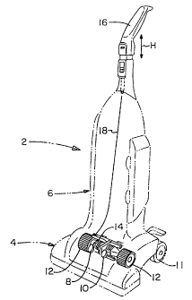
?CA 02265406 l999-03- l7E;(,Cpg55â /74:7 /\a5e/ //0. EM /47/725532â-?Hoover Case 2490T N MI E T L NTF RA LF-PR PELLED VA M LEANERBAKR DFTHEVTINF ' l Inve iThis invention pertains to self-propelled upright vacuum cleaners.More speci?cally, this invention pertains to a novel transmission neutral lockingstructure for automatically placing and locking the transmission on a self-propelledupright vacuum cleaner in its neutral position when the handle or bag housing portionof the cleaner is placed in its upright storage position.This invention also pertains to an upright vacuum cleaner having astructure for automatically engaging and rotating the agitator when the bag housingis located in a generally inclined operating position and automatically disengaging andstopping rotation of the agitator when the bag housing is located in the upright storageposition, which structure may also be manually actuated to maintain disengagementof the agitator for cleaning bare ?oors.ela ' rIt is known in the prior art to provide an upright vacuum cleaner witha transmission in the foot or lower floor engaging portion of the cleaner and atransmission actuator member mounted to the foot adjacent to the transmission. ABowden cable typically extends from the actuator on the foot to a hand grip that isreciprocally mounted for rectilinear motion to the top of the bag housing or handleportion of the cleaner. In order to prevent accidental engagement of the transmissionwhen the bag housing is in the upright storage position, it is also known to provide a?CA 02265406 2002-12-136l_935-142member on the lower end of the bag housing or handle portion of the vacuum cleanerthat will engage the transmission actuator, or actuate a member on the foot thatengages the transmission actuator, and thereby place and lock the transmissionactuator in its neutral position. Thus, if an operator were to accidentally bump thehand grip while the cleaner's bag housing is in the upright storage position and themotor is running, the transmission is prevented from being engaged and the cleaneris prevented from accidentally propelling itself across the ?oor and causing anaccident Such transmission neutral locking arrangements for self-propelled upright 'vacuum cleaners are disclosed in U.S. Patent Nos. 4,766,640; 4,347,643 and4,249,281.It is also known to place the transmission actuator on the lower end ofthe bag housing such that the actuator engages and actuates the transmission when thebag housing is in its inclined operating position and does not engage the transmissionwhen the bag housing is in its upright storage position. When the transmission is notbeing engaged by the actuator, the transmission is self-biased into an idling neutralposition. An example of this type of self-propelled vacuum cleaner can be found inU.S. Patent No. 3,618,687.As disclosed in commonly owned U.S. Patent No. 5,537,712, issued to Weber on July 23, 1996, it is lmown to I K H 2engage an agitator by pressing an idler pulley on a pivotal idler arm against theagitator drive belt, thereby placing the. agitator drive belt under tension andtransferring power to the agitator. It is also known to automatically engage anddisengage the agitator as the handle portion of the cleaner is raised and lowerediby2?CA 02265406 2002-12-13 -61935-142providing a protrusion or cam on the bag housing that contacts and pivots the idlerarm to lift the idler pulley out of engagement with the agitator drive belt. The0 United Statesâ Patent No. 5,537,712, issued to Weber on July 23, 1996, does not, however,disclose a means for shutting the agitator off for cleaning bare ?oors.S?M It is a further object of the present invention to provide an improved 'transmission neutral locking arrangement for self-propelled upright vacuum cleanersthat automatically places and locks the transmission in a neutral position when thehandle or bag housing portion of the vacuum cleaner is placed in it's upright latchedstorage position.It is a further object of the present invention to provide an improvedtransmission neutral locking arrangement for self-propelled upright vacuum cleanersthat automatically places and locks the transmission in a neutral position when theâ handle or bag housing portion of the vacuum cleaner is placed in its upright latchedstorage position and releases the transmission from the locked neutral position whenthe handle portion of the cleaner is inclined to it's operating position.It is still a further object of the present invention to provide animproved mechanism for automatically activating and de-activating the agitator in aself-propelled upright vacuum cleaner, as the handle portion of the cleaner is movedfrom the upright storage to the inclined operating position and back again.It is yet another object of the present invention to provide such anautomatic agitator drive mechanism with a means for manually setting the cleaner inan agitatorâoff mode for cleaning bare floors.3?CA 02265406 l999-03- 17Hoover Case 2490These and other objects of the present invention are achieved by thepresent invention; which provides a vacuum cleaner comprising a ?oor engagingportion; a handle portion pivotally mounted to said ?oor engaging portion for pivotalmotion relative said ?oor engaging portion between a generally upright storageposition and an inclined pivotal operating position; an agitator rotatably mounted tosaid ?oor engaging portion; a motor having an output shaft; at least one beltextending from said output shaft to said agitator for selectively drivingly connectingsaid motor to said agitator; a idler arm pivotally mounted to said ?oor engagingportion for pivotal motion between an agitator-on position in which the idler armengages said belt, thereby placing said belt under tension whereby said belt drives saidagitator, and an agitator-off position in which said idler arm does not engage said belt,thereby placing said belt in a slack condition whereby said belt does not drive saidagitator; a spring mounted between said ?oor engaging portion and said idler arm forbiasing said idler arm into said agitator-on position; a tab protruding from said handleportion such that said tab i) engages said idler arm when said handle portion is pivotedinto said storage position and thereby pivots said idler arm into said agitator-offposition and ii) moves out of engagement with said idler arm when said handle portionis pivoted to said operating position such that said spring pivots said idler arm intosaid agitator-on position; and means for selectively placing said belt under tension forselectively driving the agitator.The present invention further provides a selfâpropelled upright vacuumcleaner having a ?oor engaging portion and a generally upright handle portionpivotally attached to said ?oor engaging portion for a pivotal motion between a4?CA 02265406 l999-03- 17Hoover Case 2490generally upright storage position and a pivotal inclined operating position, at leastone ?oor engaging drive wheel mounted to and extending out a lower surface of said?oor engaging portion, a transmission operatively connected to said drive wheel anda motor drivingly connected to said transmission for selectively driving said drivewheel in forward and reverse, wherein the improvement comprises: a transmissionactuator arm pivotally mounted to said ?oor engaging portion adjacent to saidtransmission for pivotal motion about a pivot axis located generally at a centralportion of said actuator arm, a manual actuator mounted to said handle portion, saidmanual actuator being operatively connected to the actuator arm such that when anoperator actuates said manual actuator the force is transmitted from said manualactuator to said actuator arm to selectively pivot said actuator arm in first and seconddirections, respectively, from a neutral position such that said actuator arm actuatessaid transmission to place the transmission in forward and reverse, respectively; andfirst and second rigid protrusions extend from said handle portion and are located toengage said actuator arm at two locations spaced to either side of said pivot axis ofsaid actuator arm when said handle is raised to said upright storage position, wherebysaid ?rst and second protrusions place and lock said actuator arm in said neutralposition when said handle portion is pivoted to said upright storage position. A preferred embodiment of the present invention will now bedescribed, by way of example, with reference to the accompanying drawings, ofwhich:?CA 02265406 l999-03- 17Hoover Case 2490Figure 1 is a diagrammatic perspective view of a self-propelled uprightvacuum cleaner according to the present invention;Figures 2 and 3 are partial perspective views of the self-propelledupright vacuum cleaner shown in Figure 1 with the hood or housing on the lowerportion of the cleaner removed; Figure 2 illustrates the cleaner with the bag housingin the upright storage position and Figure 3 illustrates the cleaner with the bag housingin the inclined operating position;Figure 4 is a partialtop plan view of the foot portion of the vacuumcleaner with the hood removed;Figure 5 is a partially broken away cross-sectional view taken alongline V-V in ?gure 4 with the bag housing in the upright storage position; andFigure 6 is a cross-sectional view taken along line VI-VI in ?gure 4with the bag housing in the inclined operating position. EEUQNA self-propelled upright vacutun cleaner 2 according to a preferredembodiment of the present invention is diagrammatically illustrated by way ofexample in Figure 1. The cleaner includes a foot or lower ?oor engaging portion 4and an upper portion or bag housing 6 pivotally mounted to the lower portion in aconventional manner for pivotal motion from a generally upright latched storageposition, illustrated in Figure 1, to a generally inclined operating position, not shown.A manually actuated height adjustment knob 8 and a manually actuated agitator shut-off knob 10 are mounted to the foot. Rear support wheels 11 (only on of which is?CA 02265406 2002-12-1361935-142visible in ?gure 1) and drive wheels 12 cooperate to support the cleaner on a floorsurface. The drive wheels are selectively driven in forward and reverse by atransmission 14.The details of the height adjustment mechanism do not form a part ofthe present invention and are therefore notidescribed in detail herein. However, asuitable height adjustment mechanism for use with a self-propelled upright vacuumcleaner according to the present invention is disclosed in U.S. Patent No. 4,171,554.A hand grip 16 is mounted to atop of the bag housing 6 for limitedreciprocal rectilinear motion relative to the bag housing as indicated by arrow H inFigure 1. The hand grip is connected to the transmission 14 via a Bowden typecontrol cable 18 in order to enable the transmission to be automatically actuated todrive the cleaner in forward and reverse as an operator respectively pushes and pullson the hand grip.The details of the transmission do not form a part of thepresentinvention and are therefore not disclosed in detail herein. However, a suitabletransmission for use with a self-propelled upright vacuum cleaner according to thepresent invention is disclosed in expired U.S. Patent No. 3,581 ,_S9l. {Likewise, the details of thereciprocating hand grip do not fonn a part of the present invention and are thereforenot described in detail herein. Suitable hand grips for use with a self-propelled upright?CA 02265406 2002-12-1351935-142vacuum cleaner according to the present invention are disclosed in U.S. Patent Nos.3,618,687 and 5,339,916.Referring now to Figure 2, the transmission 14 is mounted to the frontedge of_ a main frame or carriage 20 and the pair of drive wheels 12 (only one ofwhich is visible "in ?gure 2) are mounted to the transmission's output shalt (not shownin Figure 2). The drive wheels are located toward the front of the carriage 20, thesupport wheels 11 are -located to the rear of the carriage and the bag housing 6.ispivotally mounted to the carriage between the drive wheels and the support wheels,such that the support wheels and the drive wheels cooperate to support the weight ofthe cleaner on a ?oor surface.. A transmission actuator arm 22 is pivotally mounted on a mountingpost 24 extending up from the carriage 20 adjacent to the transmission 14. A clutchengaging member 26 is mounted on the actuator arm. A lower end of the controlcable 18 is attached to the actuator arm 22 at a location spaced from the mounting post24. A lower end of the control cable's sheath 19 is affixed to the carriage 20 on asupport column 28 that is preferably integrally molded into the carriage. The supportcolumn may alternatively be molded into the t:ransmission housing. When an operatorpushes on the hand grip 16, the control cable pivots the actuator arm in a first directionabout the mounting post, such that the clutch engaging member 26 engages theforward drive clutch 27 of the transmission for propelling the cleaner forward acrossthe ?oor. Likewise, when an operator pulls on the hand grip, the control cable pivotsthe actuator arm in a second, opposite direction about the mounting post, such that the8?CA 02265406 l999-03- l7:1_.â.Hoover Case 2490clutch engaging member engages the reverse drive clutch 29 of the transmission forpropelling the cleaner backward across the ?oor. When the hand grip is not beingmanipulated by anvoperator, the transmission remains in a relaxed neutral position inwhich neither clutch is engaged and the actuator arm is located in a neutral positionsubstantially parallel to the input shaft of the transmission, as shown in Figure 2.First and second cams 30 and 32 (best seen in Figure 3) are de?ned by bumpsformed on the lower end of the bag housing 6 (best seen in Figure 3). The first andsecond cams are positioned on the bag housing such that, when the bag housing is inthe upright storage position, the cams engage the actuator arm 22 at two locationsspaced to either side of the actuator arm mounting post 24, such that the cams positionand lock the actuator arm in the neutral position as illustrated in Figure 2. When thebag housing is pivoted from the storage position to the inclined operating position, asillustrated in Figure 3, the first and second cams 30 and 32 move up out ofengagement with the actuator arm 22, such that the actuator arm is free to pivot aboutthe mounting post 24 and actuate the transmission 14. Lower surfaces 34 and 36 ofthe ?rst and second cams are inclined, so that as the ?rst and second cams engage theactuator arm when the bag housing 6 is pivoted from the inclined operating positionillustrated in Figure 3 to the upright storage position illustrated in Figure 2, theinclined lower surfaces 34 and 36 of the ?rst and second cams contact the actuatorarm 22 and carnmingly pivot the actuator arm into the neutral position. With thisconstruction, the actuator arm is placed and securely locked on the neutral position bythe ?rst and second cams when the bag housing is placed in the upright storageposition and accidental engagement of the transmission is prevented.9?CA 02265406 2002-12-1361935-142Referring now to ?gures 5 and 6, the lower end of the bag housing 6de?nes a motor housing 38 enclosing an electric motor 40 for powering the cleaner.A drive belt 42 extends from the motor's output shaft 43 to a first pulley 44 (notshown in Figure 6) ?xed on the input shaft 46 of the power drive transmission 14. Anagitator belt 48 extends from a second pulley 50 (shown in ghost in Figure 5) fixed onthe transmission input sha? to a third pulley S2 integrally formed on the agitator 54.âThe second pulley preferably has a smaller diameter than the ?rst pulley and the thirdpulley preferably has a diameter that is equal to the diameter of the second pulley,thereby creating a speed reduction from the ?rst pulley to the third pulley. The secondand third pulleys each preferably have a diameter of 1.5 inches and the ?rst pulleypreferably has a diameter of 2.36 inches.The agitator belt 48 has a length that is greater than the distancebetween the second pulley S0 and the agitator 54, such that there is slack in theagitator belt as illustrated in Figure 5. In order to engage the agitator, an idler pulley56 is mounted on the end of an idler arm 58 pivotally mounted in a cradle 60integrally molded into agitator housing 62 adjacent to the agitator belt 48. A spiraltorsion spring 64 (illustrated in Figure 2) is mounted in the cradle in compressionbetween the cradle and the idler arm 58. The torsion spring biases the idler arm in a?rst direction about its pivot axis and presses the idler pulley 56 against the agitatorbelt as illustrated in Figure 6, thereby placing the agitator belt under tension andtransferring power from the second pulley 50 to the agitator 54.A protrusion or third cam 66 (not shown in figure 5) is integrallymolded into the motor housing 38 and is located so that as the handle portion 6 is10?(âA 02265406â K1999-_03-.17Hoover Case 2490raised to the storage position, the protrusion 66 contacts the idler arm 58 (as seen inFigure 2) and pivots the idler arm in a second direction about its pivot axis, oppositethe first direction, thereby moving the idler pulley 56 out of engagement with theagitator belt 48 as illustrated in Figure 5, thereby disengaging the agitator from thesecond pulley 50 and from the motor 40.Using the idler pulley 56 to place the agitator belt 48 under tensionmakes it possible to employ a V-belt formed of rubber reinforced with a relativelystiff, inelastic and durable cord material to transmit power from the second pulley tothe agitator. The agitator belt has an initial circular shape or con?guration. Such aV-belt is durable enough to last for virtually the lifetime of the vacuum cleaner undernormal conditions, thereby signi?cantly reducing the need to replace the agitator belt.The drive belt 42, on the other hand, is preferably a conventional stretch belt havinga ?at or rectangular shape in cross-section that is preferably formed of a relativelyelastic rubber material. The length of the drive belt 42 is less than the distancebetween the motor shaft 43 and the ?rst pulley 44, whereby the drive belt must bestretched to be mounted between the motor shaft and the ?rst pulley. Thus, the drivebelt is mounted under tension, such that the natural elasticity of the drive beltmaintains the drive belt under tension for transmitting power from the motor 40 to thetransmission 14.The drive belt according to the present invention is less expensive andless durable than the agitator belt. The drive belt is designed to slip on the motor'soutput shaft when the agitator is accidentally stalled. Thus, the drive belt serves as anoverload clutch that allows the motor to continue to rotate when the agitator stalls,ll?....Nâ "A 02265406 l999v'03'l7mHoover Case 2490thereby preventing the motor from being stalled and burning out. As a result of itsless durable nature and its function as an overload clutch, the drive belt will likelyrequire replacement during the lifetime of the vacuum cleaner under normal operatingconditions. As discussed above, the agitator belt is designed to last considerablylonger than the drive belt. Therefore, the second pulley 50 is located on thetransmission input shaft inside of the ?rst pulley 44, so that the agitator belt 48 doesnot have to be removed in order to replace the drive belt 42.Still referring to ?gures 5 and 6, lower and upper belt guides 68 and70 are molded into a bottom plate 72 and into a top plate 74 of the agitator housing62. The lower belt guide 68 formed in the bottom plate is a vertical wall having aninclined top surface or edge that lies adjacent and generally parallel to a lower expanse76 of the agitator belt 48. A similar wall 70 having a lower edge that lies adjacent toan upper expanse 78 of the agitator belt and a rib 80 (not shown in Figure 5) havinga lower end adjacent to the upper expanse of the agitator belt are molded into the topplate. The bottom plate and the top plate cooperate to de?ne a semi-cylindricalchamber having an inner peripheral surface 82 that closely surrounds the outerperipheral surface of the agitator belt where the agitator belt is wrapped around thethird pulley 52 formed on the agitator 54.When the idler pulley 56 is moved away from the agitator belt 48, thenatural stiffness and resiliency of the agitator belt causes the upper 78 and lower 76expanses of the agitator belt to bow radially outwardly toward the agitator belts initialcircular shape. Since further outward bowing of the upper and lower expanses of theagitator belt is prevented by the belt guides 68 and 70, the upper and lower expanses12? _,_.._...,__,_..,.CA 02265406 1999-03-17___.____._____~-Hoover Case 2490of the agitator belt are maintained in a substantially straight planar con?guration. Asthe upper expanse 78 of the agitator belt straightens, the ends of the agitator belt, i.e.where the agitator belt is wrapped around the second 50 and the third 52 pulleys,move away from each other. Since the end of the agitator belt wrapped around thethird pulley 52 is prevented from moving away from the third pulley by the closeproximity of the inner peripheral surface 82 of the annular chamber de?ned by the topplate 74 and the bottom plate 72 of the agitator housing, the end of the agitator beltwrapped around the second pulley 52 moves away from the second pulley asillustrated in Figure 5. Thus, the agitator belt 48 is lifted clear of the second pulley.It is critical that the agitator belt be lifted from the second pulley rather than the thirdpulley, because the second pulley is continuously driven by the motor via the drivebelt 42. If the agitator belt were to remain in contact with the second pulley when notunder tension, the agitator belt would slip on the second pulley, and the resulting?iction would damage both the agitator belt and the second pulley.In a preferred embodiment of the present invention, when the idlerpulley 56 is located in the agitator-off position, as illustrated in Figure 5, the outerperipheral surface of the idler pulley is substantially tangent to a plane extending fromthe lower surface of the upper belt guide 70 and the lower edge of the rib 80. Thus,the idler pulley cooperates with the upper belt guide and with the rib in preventing theupper expanse 78 of the agitator belt from bowing outward when the idler pulley ismoved to the agitator-off position.Referring again to Figures 2 and 3, the agitator shut-off knob 10 ismounted to the hood (not shown in Figures 2 and 3 ) on a slide 84 for reciprocal13?CA 02265406 l999-03- 17Hoover Case 2490movement between an agitatorâon position illustrated in Figure 3 to an agitator-offposition illustrated in Figure 2. A ?nger 86 extends out from an end of the slideadjacent to the agitator belt 48 and extends toward the agitator belt. When cleaningcarpeted ?oors, the agitator shut-off knob is located in the agitator-on position, so thatthe agitator is driven for agitating the carpet in a conventional manner. When it isdesired to clean bare ?oors, the bag housing 6 is ?rst pivoted into the latched storageposition in which the idler pulley 56 is disengaged from the agitator belt 48 and theagitator is off, as illustrated in Figure 2. The operator then slides the agitator shut-offknob 10 to the right, as viewed in Figures 2 and 3, into the agitator-off positionillustrated in Figure 2. When the agitator shut-off knob is in the agitator-off position,the ?nger 86 extends under the idler arm 58. When the operator subsequently inclinesthe bag housing into the operating position for cleaning the ?oor, the ?nger 86 retainsthe idler arm in the disengaged position, such that the agitator remains disengaged.It will be appreciated that a manual agitator shut-off knob with a ?ngeraccording to the present invention could be used in a non-propelled upright vacuumcleaner having an automatically actuated belt tensioning idler pulley, such as thecleaner disclosed in previously mentioned U.S. Patent no. 5,527,712, in order toprovide such a cleaner with an agitator-off bare ?oor cleaning mode of operation.It will further be appreciated that any suitable control link may besubstituted for the disclosed the Bowden control cable without departing from thescope of the present invention. For example, a ?exible strap, a rigid link or a systemof rigid links may be substituted for the control cable. Similarly, a drive belt has beendisclosed for drivingly connecting the motor to the transmission. One of skill in the14?CA 02265406 1999-03-17 , ...-....._ . _.-Hoover Case 2490art will also recognize that the transmission may alternatively be connected to themotor by any suitable drive train, such as a gear train for example.The present invention has been described above using a preferredembodiment by way of example only. Obvious modi?cations within the scope of thepresent invention will become apparent to one of ordinary skill upon reading theabove description and viewing the appended drawings. The present inventiondescribed above and as claimed in the appended claims is intended to include all suchobvious modi?cations within the scope of the present invention.15