Note: Descriptions are shown in the official language in which they were submitted.
CA 02266032 1999-03-05
WO 98/10970 PCT/US97/16051
RAILROAD CAR HAVING COLD FORMED CENTER SILL
BACKGROUND OF THE INVENTION
1. Field of the Invention
This invention relates, in general, to railroad
cars and, more specifically, to a cold formed center sill
and its method of manufacture.
2. Summary of the Prior Art
The center sill is the primary structural member
of the underframe of a railcar. It is subjected to the
buff and draft forces created during operation of the
railcar and normally extends as a continuous member along
the :length of the car body. In the past, center sills have
possessed many different cross-sectional configurations
depending on the type of railcar and other considerations.
Center sills have been in the shape of hat designs, C-
sections and other configurations. Regardless of its
particular shape, it is well known to form a center sill by
welding a plurality of hot rolled flat pieces or hot rolled
sections together as a unit along its substantial length.
The use of numerous welds to manufacture center sills
presents several long-existing problems. Because numerous
welds are needed, the reliance on this process to fabricate
a finished center sill is inefficient from both a cost and
productivity standpoint. The application of the welds
along the lengths of the pieces being joined as a center
sill is labor-intensive and cannot attain high-speed
production. In addition, the application of multiple welds
heats the material being joined and results in heat
distortion and warpage. Warpage creates deviations in the
straightness or acceptable tolerances of the center sill
being formed. As a result, further physical steps are
needed to finish the welded center sill unit and conform it
to acceptable tolerances in camber, sweep and twist to be
suitable for use in a railroad car. Existing center sills
are subject to crippling of the webs which requires thicker
cross sections at critical structural areas. Furthermore,
hot rolled sections do not always result in the desired
tolerances for the finished camber of the sill. As an
CA 02266032 1999-03-05
WO 98/10970 PCTIUS97/16051
additional important consideration, a welded center sill is
an inherently heavy structure due to its design and
fabrication technique. Accordingly, it is desirable in the
prior art to provide an improved, lightweight center sill
in which the necessity of a plurality of welds or other
securement techniques are eliminated.
SUMMARY OF THE INVENTION
It is an objective of this invention to provide
an improved center sill capable of being cold formed into
a straight member having close tolerances. The various
configurations of the several embodiments of the invention
are cold formed at a plurality of cold rolling stations
from a plate or sheet of coiled steel. The flat sheet
undergoes progressive formation at each rolling station
whereby drawings of the steps of shaping developed by each
roll station, when superimposed, form a flower diagram to
assist the roll tooling designer. The center sills herein
disclosed can be formed on a continuous basis without
interruption between separate center sills. One unique
cold forming process of the invention allows center sills
having a thickness up to 5/8 inch to be formed without the
use of welds as in the prior art. Because the bent
sections forming the shape of the center sill are cold
worked numerous times during working, the material is
strengthened to resist crippling and produce a stronger
cross section without thicker sections or reinforcing
material. The center sills are open at the bottom to
provide desired access within the center sill body. Some
of the configurations of the center sill include extra
structural features that provide enhanced strength
characteristics without adding a significant weight.
A complete understanding of the invention will be
obtained from the following description when taken in
connection with the accompanying drawing figures wherein
like reference characters identify like parts throughout.
-2-
CA 02266032 1999-03-05
WO 98/10970 PCT/US97/16051
BRIEF DESCRIPTION OF THE DRAWINGS
Fig. 1 is a side elevational view, with parts in
section, showing any of the center sill embodiments of the
invention on a rail car;
Fig. 2 is a cross-sectional view of a first
embodiment of a single piece center sill for use with a
railroad car such as illustrated in Fig. 1;
Fig. 3 is a cross-sectional view of a second
embodiment of the single piece continuous center sill
invention for use with a railroad car such as illustrated
in Fig. 1;
Fig. 4 is a cross-sectional view of a third
embodiment of the single piece center sill of the invention
for use with a railroad car such as illustrated Fig. 1;
Fig. 5 is a schematic diagram of the cold forming
apparatus for forming the cold formed center sill of the
several embodiments of the invention; and
Fig. 6 is a cross-sectional view of a fourth
embodiment of the cold formed center sill of the invention
for use with a railroad car such as illustrated in Fig. 1.
DESCRIPTION OF THE PREFERRED EMBODIMENTS
Referring to Fig. 1, there is illustrated a
railroad gondola car 2 for carrying commodities such as
coal, gravel and the like and having an underbody carried
by opposed truck assemblies 4. The underbody of the
railroad car of the invention includes a continuous single
piece center sill 6 extending substantially the entire
length of the car. A railcar body 7 is attached to the
underframe. As will be apparent from the following
description, the single piece center sills of several
embodiments of the invention provide significant advantages
over prior center sills and contribute to a lightweight,
economical car design. Although the center sills of the
invention are shown with reference to the gondola car of
Fig. 1 by way of illustration, it is within the scope of
the invention to use the single or the two-piece center
sill herein disclosed with any type or design of rail
-3-
CA 02266032 1999-03-05
WO 98/10970 PCTIUS97/16051
freight car in which the advantages of the invention are
desired.
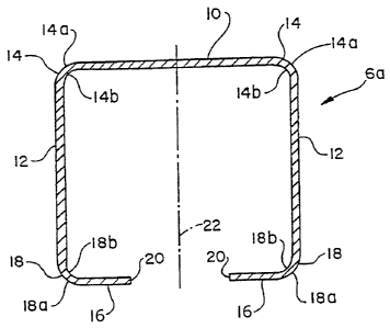
Referring now to Fig. 2, there is illustrated the
first embodiment of the single piece center sill of the
invention, generally designated by reference numeral Ga.
The center sill 6a of Fig. 2 is formed from a suitable
steel by a cold rolling process to be described. The
center sill 6a is formed in a generally rectangular
configuration from a flat one-piece plate or coiled sheet
of steel and is continuous along its length. The center
sill is formed by bent sections created in the cold forming
process from a material having a thickness of up to 5/8
inch with thicknesses of either 3/8 inch to 5/8 inch being
preferable. The center sill 6a includes an upper flat top
wall 10 and a pair of flat side sections or webs 12, each
of generally constant thicknesses.
The top wall 10 and pair of side sections 12 are
joined together at right angles by upper curved sections 14
having curved outer surfaces 14a and curved inner surfaces
14b, the latter being formed about a common radius such as,
for example, 15/16 inch. The bottom sections 16 of the
center sill 6a are inwardly formed horizontally at right
angles to the side sections 12 through curved connecting
sections 18 having curved outer surfaces 18a and curved
inner surfaces 18b, the latter being of constant radius
such as, for example, approximately 15/16 inch. The bottom
sections 16 terminate with a free end 20 to form a
longitudinal opening 22 through which access within the
center sill 6a is provided. By way of example, the bottom
sections 16 forming the bottom portions of the center sill
may each extend approximately 4 inches from the side
sections 12 and create the bottom opening 22 having a width
of approximately 5 to 6 inches. The center sill 6a
preferably possesses an average yield strength throughout
its length of at least 70,000 PSI and an average tensile
strength of at least 80,000 PSI to easily meet all strength
requirements for the center sill, but these values may be
-4-
CA 02266032 1999-03-05
WO 98/10970 PCT/US97/16051
as low as 50,000 PSI and 65,000 PSI, respectively. The
curved sections 14 and 18 are cold worked numerous times
during the cold rolling process. As a result, the material
is cold hardened and strengthened at sections 14 and 18 as
compared to its original unformed state. The resulting
cross section does not require thicker sections or added
material as in the prior art and provides a lightweight,
high-strength member.
Referring to Fig. 3, there is illustrated the
second embodiment of the center sill of the invention. The
center sill 6b of Fig. 3 includes upper top wall 30,
opposite side sections or webs 32 and bent in bottom
portions 34 creating opening 35. The top walls 30, opposed
side sections 32 and bottom portions 34 are respectively
interconnected by upper curved sections 36 and lower curved
sections 38 having a similar configuration as .the
embodiment of Fig. 3. As in the prior art, the curved
sect.ions 36 and 38 are cold hardened during rolling for
increased strength. The center sill 6b further includes a
pair of upright internal flange portions 40 extending
upward and being joined to bottom portions 34 by curved
sections 42 of constant radius similar as curved sections
36 and 38. The center sill 6b is cold formed in
progressive steps as the previous embodiment to obtain its
conf'iguration, but initially from a wider sheet or plate
material. The curved sections 42 are also cold hardened
during rolling for increased strength. As a result, the
cross section of the center sill 6b includes more material
for similar external dimensions than the configuration of
the embodiment of Fig. 2 because of flange portions 40 to
provide greater strength characteristics and high
resistance to buckling, with only a minimum increase in
weight. The thickness of center sill of Fig. 3 is
preferably up to 5/8 inch, with 3/8 to 5/8 inch being
preferred. The configuration exceeds the strength
characteristics of the preceding embodiment for the same
-5-
CA 02266032 2005-08-16
dimensions and material and is also continuously formed from
a one-piece coiled sheet or plate.
Referring now to Fig. 4, there is illustrated the
third embodiment of the invention, generally designated by
reference numeral 6c. The configuration of the center sill
6c is also similar to the embodiment of Fig. 2, but further
includes a pair of inwardly disposed ribs 50 rolled out of
the two side sections for webs 52 of the center sill 6c. The
inwardly directed ribs 50 serve as stiffeners for the
elongated center sill and are cold formed during the first
stations in the rolling process. The center sill 6c includes
a top wall 54 which is oriented at 900 to side sections 52
by a curved portion 55 having an approximate radius, for
example, of 15/16 inch and the like. The ribs 52 include
inwardly extending connecting portion 56 of a length less
than an inch and have a flat internal wall 57 to rigidize the
center sill. The connecting portions 56 are also worked
hardened as are curved portions 55. The bottom of the center
sill includes a pair of partial horizontal bottom sections
58 integral to side sections 52 by curved sections 59. The
bottom sections define longitudinal bottom opening 60 along
the center sill 6c. Although other sizes and dimensions may
be employed in accordance with the invention, the center sill
6c may have a width of approximately 1 foot, 13/16 inch and
a height of approximately 1 foot, 15/16 inch and the like.
The embodiments described with reference to Figs. 2 and 3 may
have similar or external dimensions. The internal wall 57
of the ribs 50 may extend for a height of 3 to 4 inches or
other suitable dimension. The bottom sections 58 may extend
for approximately 4 inches at the bottom. The center sill
6c may be cold formed from a steel having a preferable
tensile strength of 70 KSI, but also as low as 50 KSI.
Center sill 6c provides additional yield strength due to the
presence of the stiffening ribs 50 for the same size and
material as compared to the embodiment of Fig. 2,
-6-
CA 02266032 1999-03-05
WO 98/10970 PCT/US97/16051
but only adds minimal weight to the overall structure of
the beam.
Referring now to Fig. 5, a schematic view of the
technique of cold rolling the various embodiments of the
center sill of the invention is illustrated. Coiled steel
in sheet form is carried by a conventional uncoiler 70. In
the embodiment of Fig. 2, the width of the coiled metal may
be, for example, 46 inches. As is well known, the stations
of the rolling mill 74 comprise roll formers positioned at
different orientations at each station to cause the
progressive deformation of the sheet material into the
desired configuration. During the initial setup of the
process, the steel coil is opened and fed through a
flattener apparatus 72 to remove coil set. The lead end of
the coil is trimmed and joined to the trailing end of the
previous length of material in a shear welder. The plate
or sheet material is fed to a forming mill 74 comprising 10
or more pairs of roll forming stations to progressively
forni the flat material into the finished shape as shown in
Figs. 2, 3 and 4.
In the formation of the embodiment of Fig. 2, the
flat: plate or sheet material undergoes bending at a
plurality of stations, such as 10 or more, that create the
final cold formed shape of the center sill of Fig. 2 to be
formed. In connection with the embodiment of Fig. 3, added
stations are required for the first several steps to form
the bent up internal flange portions 40. As to the
embodiment of Fig. 4, the rib sections 50 are also formed
during the first several steps of the rolling process
during passage of the sheet material through the rolling
mill. 74.
After the final station in rolling mill 74 is
passed, the formed single piece center sill is delivered to
a cutoff press 76 which cuts the center sill to the desired
length without stopping the rolling process. The separated
center sill then is conveyed to a conveyor 78 on which the
profile of the center sill is inspected to determine
-7-
CA 02266032 1999-03-05
WO 98/10970 PCT/US97/16051
whether its dimensions are correct and whether acceptable
tolerances of camber, sweep and twist have been maintained.
The cold forming process of the invention attains
significantly close tolerances in the final product of the
center sill by a process that is capable of high production
with minimum labor. This capability provides a vastly
superior product with economical manufacture and a beam
structure of high quality and precise shape. The single
piece center sill of the invention is lightweight, being
approximately 1,000 pounds or more lighter than
conventional welded sills.
Referring now to Fig. 6, there is illustrated a
fourth embodiment of the present invention, generally
designated by reference numeral 6d. The configuration of
the center sill 6d is similar to the previous embodiments
and includes a top wall 80 connected to a pair of side
sections 82 through upper curved sections 84. Each side
section 82 is connected to a bottom section 86 through
lower curved sections 88. Each bottom section 86
terminates at a free end 90 forming a longitudinal opening
92 therebetween. The dimension of the center sill 6d is
substantially the same as center sill 6a described above in
connection with Fig. 2. The center sill 6d differs from
center sill 6a by being formed of two separate cold formed
halves connected by a single longitudinal weld 94. Fig. 6
also shows a bottom tie plate 96 and a bottom flange
stiffener 98 attached to the center sill 6d which may be
required on certain railcar designs.
The two-piece cold formed center sill 6d
maintains many of the advantages of the one-piece
embodiments 6a, 6b and 6c described above. The cold
forming process provides sections with significantly less
variance from the specified section than the prior art hot
rolled sections. Additionally, the use of a single weld
minimizes the assembly time associated with prior multi-
weld configurations. The center sill 6d also exhibits a
significant weight savings over the known prior art center
-8-
CA 02266032 1999-03-05
WO 98/10970 PCT/US97/16051
sills. The two-piece center sill 6d is advantageous where
the specific rolling mill 74 cannot accommodate the
complete center sill cross section. A rolling mill 74 may
not contain enough stations to complete the entire cross
section. In this case, the rolling mill can form two cold
formed halves to form the center sill 6d of Fig. 5. The
cross sections of the center sills 6b and 6c shown in Figs.
3 and 4 may similarly be formed of two halves subsequently
welded together.
Superior strength characteristics of the center
sill of the invention are attained by using a steel such as
an ASTM A607, grade 70 or an ASTM A935, grade 70 for a
plate or sheet having a thickness 3/8 inch. With a thicker
sheet of material, such as 1/2 inch, an ASTM A607, grade 50
steel may be used with coiled plate or an ASTM A572, grade
50 with a coiled sheet. One suitable ASTM A607, grade 70
steel for thicknesses of 3/8 inch is known as Type 1, sold
under the trademark Stelmax 70''. Stelmax 70T" has an
expected yield strength of 76 KSI and a tensile,strength of
86 PSi. Other steels of the type described demonstrating
similar properties may be used with the invention.
Some of the advantages of the present invention
are highlighted with a comparison of the present invention
with a standard center sill.
-9-
CA 02266032 1999-03-05
WO 98/10970 PCT/US97/16051
3/8 Inch 3/8 34 Inch M. inch
Thick Inch Thick.. Thick
One- Thick. One- Two-
Piece Two- Piece Piece
Standard Center Piec.e Center Center
Center Sill 6b Center Sill6b Sill 6d
Sill w/upturned Sill 6d
f lange W/o
upturned
f l ange
Minimum 50 70 70 50 50
Yield
Point
(KSI)
Minimum 65 80 80 60 60
Tensile
(KSI)
Weight Per 82.4 60.2 56.5 80.0 74.4
Foot
Additionally, a 3K frame Bethgon Coalporter(D
railcar utilizing the center sill 3/8 Inch 6d was loaded to
286K gross rail load and standard AAR loads and load
factors were applied. This was compared to the same type
of railcar utilizing a standard center sill. The margin of
safety against yield failure of the material in the center
sill was greater for center sill 6d.
The above comparison illustrates that the cold
formed center sills of the present invention offer
significant advantages over the prior art center sills
without detrimental drawbacks. It will be apparent to
those of ordinary skill in the art that various changes may
be made to the present invention without departing from the
spirit and scope thereof. Consequently, the present
invention is intended to be defined by the appended claims.
-10-