Note: Descriptions are shown in the official language in which they were submitted.
CA 02266065 1999-04-06
'title of the Invention
BREWING APPLIANCE HAVING A TOWER WITH A WATER RESERVOIR AND
BREWING BASKET AND AN ADJACENTLY POSITIONED PITCHER RECEPTACLE
Field of the Invention
The present invention pertains generally to appliances for preparing brewed
beverages
such as coffee or tea, and more particularly to automated brewing appliances
which have a
brewing water reservoir) a heat source for heating water received from the
water reservoir, a
brewing chamber for holding a brewing material such as coffee or tea, and a
receptacle such as
a pitcher or carafe.
Background of the Invention
Many different types of automated brewing appliances have been developed to
rapidly
produce hot brewed beverages. One of the most common arrangements is to
provide a water
reservoir which drains into a heated conduit. As water within the conduit is
heated, it expands
and is forced from the heated conduit into a brewing chamber where it is
distributed over
coffee grounds or tea leaves. The resulting brewed beverage then drains
directly from the
brewing chamber into a pitcher or carafe which is placed underneath the
brewing chamber.
Another common arrangement is to position the heated conduit underneath a
platform on which
the pitcher is held in order to transfer some heat to the pitcher and the
beverage contents.
Some disadvantages with this type of design are that the brewing chamber must
be
made to extend out over the pitcher platform. When the pitcher is removed from
the heated
platform, excess liquid in the brewing chamber may drip directly onto the
platform. Also, the
brewing chamber and the pitcher platform generally extend out in front of the
appliance,
requiring the water reservoir to be at the back and therefore somewhat
difficult to access and
fill. Also, the pitcher or carafe must be made of a heat resistant material
such as glass or
metal, and is therefore not typically insulated with less heat resistant
materials such as plastic
and foam.
Summary of the Invention
The present invention provides a novel brewing appliance wherein the pitcher
is
positioned adjacent to a water reservoir and brewing basket tower. In
accordance with one
aspect of the invention, a brewing appliance includes a tower including a
water reservoir, a
brewing basket, and a heated conduit connected to the water reservoir and
connected to the
brewing basket) the brewing basket having a sloped door and a drain hole at an
edge of the
sloped floor, a flow rate control valve assembly associated with the brewing
basket drain hole,
and a pitcher positionable adjacent to the tower so that a brewed beverage
drains from the
brewing basket through the drain hole into the pitcher.
I .1C'( ) I-r.JC~Sn~=' I)(l l ;
CA 02266065 1999-04-06
In accordance with anotl»r ,~~I~ect of the invention, a beverage preparatit,n
device h<ls
a water reservoir for holdin~~ . quan~iw of water for producing a beverage, a
brewing basket
for holding a brewin~~ material) the hrwvin'~ basket having a wall and a
sloped Iloor and a drain
in the sloped floor near the wall, the drain hole being positioned to allow
passage of liquid to
the exterior of the beverage preparation device) and means for heating water
connected to the
water reservoir and connected to a sl~c,wer nozzle positioned to distribute
heated water into the
brewing basket.
These and other aspects of the present invention are herein described in
particularized
detail with reference to the accompanying Figures.
Brief Description of the Figures
In the accompanying Figures:
FIG. 1 is a cross-sectional viem of the brewing appliance of the present
invention;
FIG. IA is a top view of the interior of the base of the brewing appliance of
the present
mventton;
FIG. 1B is a partial cross-sectional view of the base of the brewing appli.nce
of the
present invention;
FIG. 2 is an elevation view of the brewing appliance of the present invention;
FIG. 3 is a top view of the brewing appliance of the present invention;
FIG. 4 is a elevation view of the water reservoir and brewing basket tower of
the
present invention;
FIG. S is a perspective view of the brew basket of the present invention:
FIG. 6 is a cross-sectional view of the vent structure in the cover of the
water reservoir
and brewing basket tower of the present invention;
FIG. 7 is a cross-sectional view of an upper region of the brewing appliance
of the
present invention;
FIG. 8 is a top view of the tower portion of the brewing appliance of the
present
invention, shown without the lid;
FIG. 9 is a cross-sectional view of the mounting of the shower nozzle with a
fitting in
the brewing appliance of the present invention, and
y ,utrnn.W'SUO~zuoc:i;
CA 02266065 1999-04-06
FIG. l0 is an elevation view of a tittin~~ fur the shower nozzle of the
brewing appliance
oC the present invention.
Detailed Description of Preferred and Alternate Embodiments
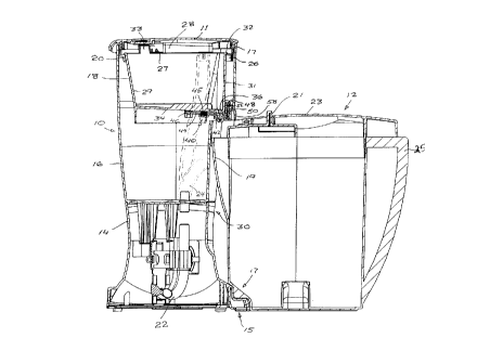
As shown in FIGS. 1-4, the brewing appliance of the invention includes a water
rcs~rvoir and brewing basket tower indicated ~~cnerally at 10, and a pitcher
12 which is
positionable adjacent to the tower 10. The tower 10 has a base 14 which
supports a water
reservoir 16. A brewing basket 18 is positioned within an upper region of the
water reservoir,
<ind is supported by a mounting ring 20 attached to a top of the water
reservoir wall 17. The
tower 10 also has a lid 11 which may be hingedly attached to a side wall of
the tower.
Water drains from the water reservoir into a heated conduit 22 mounted in the
base 14,
and connected to a heated water conduit 24 which extends and attaches to a
fitting 26 which is
connected to a shower nozzle 28, which extends out over the brewing basket 18.
A one-way
check valve (not shown) in the conduit between the water reservoir 16 and the
heated conduit
prevents heated water from entering the water reservoir 16. The shower nozzle
28 is swivel
mounted at fitting 26 within a generally horizontal t7ange section 21 of the
mounting ring 20.
The shower nozzle 28 can thus be swiveled away from the brewing basket 18 to
allow the
brewing basket to be removed from the tower.
As shown in FIGS. 9 and 10, fitting 26, which is preferably formed integrally
with or
attached to mounting ring 20, has opposed helical tracks 261 which receive
pins 281 which
extend from the distending end 282 of the shower nozzle 28. The pins 281 are
deflectable so
that once they engage with the helical tracks 261 the shower nozzle 28 is
permanently engaged
with fitting 26. As the shower nozzle 28 is rotated within the tracks 261 to
the side of the
mounting ring 20, the shower nozzle 28 is raised to the extent of the helix,
thereby preventing
the lid 11 from being put in a closed position, unless the shower nozzle 28 is
properly
positioned over the brewing basket.
As shown in FIGS. lA and 1B, the heated conduit 22 may be mounted in a
generally
vertical orientation within the base 14 of the tower 10, by attachment to a
bracket 13 which is
secured to a mounting block 113 on the interior side of the base 14. A
thermostat 70 is also
mounted on the bracket 13 in contact with or close proximity to the heated
conduit 22. In the
mounting block 113 is a spring biased actuator button operative to contact a
reset plunger 71 of
the thermostat 70, which operates to initiate a power supply to the heated
conduit 22.
As shown in FIGS. 1, 5 and 8, the shower nozzle 28 is preferably a generally
closed
conduit which expand at the distal end and have an array of generally radially
spaced spray
orifices 27 at the frontal wall or edge of the shower nozzle. The spray
orifices 27 are
generally elongate vertical openings extending from a bottom of the shower
head conduit, each
having a generally arched top. This design has been found to provide improved
water
distribution over the entire brewing basket 18 and, of course, the brewing
material therein.
This is a critical aspect of the brewing performance of the appliance) as
increased or
maaicnized distribution of heated water over the brewin~= material maximizes
extraction of
'J ~ ~I-I~JCV'",=- I>c)c.l;
CA 02266065 1999-04-06
fl,mcrr, and reduces c>r eliminates ,,ny puolin'1 ot~ waUr within the hr~wina
haskut which can
result in uvert7ow from the basket.
The tower IO has a recess 30 on one side conti~~ured to receive a portion of
the pitcher
12 as it is positioned adjacent the tower. The base 14 includes a docking
station 15 (also
shown in FIG. 4) which engages with a correspondingly formed recess and notch
17 in a lower
re:~ioo of the pitcher 12. The notch 17 of the pitcher 12 is aligned with a
spout 19 on the
pitcher. A slide mounted spout cover 21 is incorporated into the pitcher lid
23. A portion of
the pitcher lid 23 extends over the pitcher handle 25.
The brewing basket 18 has a generally tapered side wall 29, a generally
vertical side
wall 31, and an annular flange 32 at the top of the side walls which overlaps
the mounting ring
20. A handle 33 extends from the flange to provide a grip for removing the
brewing basket
from the tower so that the water reservoir 16 can be filled. The brewing
basket 18 fits within
the mounting ring 20 in an indexed manner so that the bottom floor 34 of the
basket is sloped
toward the recessed side 30 of the tower in which the pitcher 12 fits. A
brewing basket drain
hole 36 is preferably located at the lowermost point of the sloped brewing
basket floor 34, but
may alternatively be located anywhere in the floor 34. Also, any location of
the drain hole
where drainage therethrough leads to the exterior of the tower, i.e. , to the
recess 30 or any
other point of exit, is within the scope of the invention. The drain hole 36
is thus positioned
above the recess 30 in the tower, and over the top opening to the spout 19 of
the pitcher 12
when the pitcher is engaged in the docking station 15 within tower recess 30.
By this
arrangement, as water is introduced into the brewing basket 18, and passes
through a brewing
material and filter in the brewing basket, a brewed beverage drains from the
brewing basket 18
through drain hole 36 into the spout 19 of pitcher 12.
The rate of flow of liquid through the brewing basket is controlled by a valve
assembly
40 integral with the brewing basket 18. The valve assembly 40 includes a
frusto-conical valve
element 42 positioned within the drain hole 36 by a valve arm 44. The valve
arm 44 is
generally vertically pivotally mounted at end 46, and biased away from the
basket floor 34 by a
spring 45. The valve arm 44 extends past the valve element 42 and turns upward
outside of
the outer wall of the brewing basket, terminating in a cam follower 48. A
sliding cam flow
t-ate eontro~e~A is mounted within a channel 52 in the side wall of the tower
10.
As best shown in FIG. 5) the controller 50 has an angled cam surface 54 on
which the
cam follower 48 rides. As the controller is laterally translated within the
channel 52, the cam
follower 48 is moved up or down upon the angled cam surface 54, pivoting the
valve arm 44
about end 46, and thereby moving the position of the valve element 42 relative
to the drain
hole 36. For example, with the controller laterally slid to position the
uppermost point of the
cam surface 54 under the cam follower 48, the valve element 42 is at a maximum
advanced
position in the drain hole 36) thus restricting the liquid flow rate from the
brewing basket 18.
The valve element 42 may also include an axial bore so that even with the
valve
element in the most advanced position within the drain hole 36, a minimum tlow
rate through
the valve element is assured. With the controller 50 laterally slid to
position the cam follower
;~ ~,a~~c>rr~csom~ uoc: ~ ;
_ ... .. ..,~...._ _
CA 02266065 1999-04-06
~l~ at tltc lowest point of the cam surface 54) the valve clement 42 is
substanti,lf_ retracted
I~ron~ the drain hole 36) thus maximizing the tlow rate from the brewing
bashct. The controller
is provided with a slide handle 58 which is accessible from the exterior of
the twv~r L0.
In the event that drain hole 36 becomes completely occluded, the brewing
basket 18 is
provided with an alternate drain hole 361, as shown in FIG. 8, at an elevation
sli;~htly above
drain hole 36.
As shown in FIGS. 3 and 6) the lid 11 of the tower 10 is provided with
openings 60
which allow steam) generated from the hot water introduced to the brewing
chamber, to escape
and thereby reduce condensation and heat level on the interior of the lid. As
shown in FIG. 6)
the openings 60 are novelty configured with a deflector 62 which is
countersunk or offset from
the opening 60 but generally aligned with the opening) creating gaps 63
between the deflector
62 and the opening 60 through which steam escapes.
As shown in FIG. 7, the lid 11 includes a tlange 111 which directs any
condensate
which does collect on the interior of the lid into the brewing basket 18. Ribs
on the interior of
the lid 18 direct the condensate to flow toward flange 111 when the lid 11 is
in the opened
position shown. As shown in FIGS. 7 and 8) the mounting ring 20 includes a
drip ledge 201
which extends out beyond the wall of the tower 10 to catch any condensate from
the lid and
direct it toward the brewing basket.
To prepare a hot brewed beverage such as tea or coffee with the appliance, the
tower
lid 11 is opened and the shower nozzle 28 swung to the side of the mounting
ring 20. The
brewing basket 18 removed, and the water reservoir 10 filled with a sufficient
amount of
water. The maximum water level within the reservoir is near the bottom of the
brewing
basket. The brewing basket 18 is loaded with a filter such as a paper filter
and a brewing
material such as coffee grounds or tea leaves or other flavoring agent, and
positioned within
the tower as described. The shower nozzle 28 is repositioned over the brewing
basket. The
lid 11 is closed. The flow rate (or brew strength) is selected by operation of
slide 58 of the
valve assembly 40. The pitcher 12 is positioned adjacent to the tower and
engaged in the
docking station 15 as described. A power control circuit (not shown) connected
to the heated
conduit 22 is activated to provide thermal energy to the heated conduit to
begin heating water
from the water reservoir and transferring heated water to the brewing basket
18. A brewed
beverage then drains from the brewing basket into the pitcher as described.
~: ~sco~rtvcsoo> >. ooc: i ;