Note: Descriptions are shown in the official language in which they were submitted.
CA 02266379 1999-03-22
W O 98112581 PCTnUS97/lS993
R~l~OREl:LECTlVE MICROPRISMAT[C MATERI.~L W~ CONCAVE BASE FACE CURVA-
TURE
Backqround of the Invention
Retroreflective sheet material is widely employed
for a variety of safety and decorative purposes, and is
particularly useful when the need for night time
visibility is significant under conditions of low
ambient light. In retroreflective materials, the light
rays impinging upon the front surface are reflected back
towards the source of the illumination. In situations
where headlights or search lights on boats and aircraft
are the only source of illumination, this ability to
retroreflect in a controlled cone the bulk of the rays
falling thereon is especially significant for warning
signs, delineators and the like.
Applicant's assignee, Reflexite Corporation, has
been marketing under the trademark REFLEXITE~,
ref~ective sheeting employing microprism formulations to
produce such retroreflection. Illustrative of such
materials is Rowland U.S. Letters Pat. No. 3,689,346
granted September 5, 1972, the teachings of which are
incorporated herein by reference in their entirety.
Among the applications for such retroreflective
materials are reflective tapes and patches for clothing,
reflective vests and belts, bands for posts and barrels,
traffic cone collars, highway signs, warning reflectors
and the like.
Typical prior art retrorei~lective sheeting 10 is
formed of cube-corner prisms having a flat base face 11
abutting a carrier film 2 protected by a coating layer 4
as shown in Fig. 1.
As is known, the three reElecting adjacent surfaces
of a cube corner prism rotate che direction of the
CA 02266379 l999-03-22
W O 98112581 PCT~U597tlS9g3
incoming light 26 or 28 by an angle of 180~, and the
light exits parallel to the incident direction.
Retroreflection of light rays entering the prisms may be
seen in Fig. 1 wherein a reflective metal deposit 24 is
shown on some of the prisms 12A while an air interface
is shown for other prisms 12B. A light ray 26 entering
the front or base face of the sheeting 10 and entering
the prism 12A is reflected (by the interface of the
prism material with the metallic coating 24) to another
face of the prism (and again reflected to the third face
of the prism, although not so illustrated). Ultimately,
the ray 26 is redirected from the prism 12A towards the
front face of the sheeting 10 from which it exits in a
path substantially parallel to the incident ray.
Similarly, the light ray 28 iS redirected by the prism
12B/air 6 interface at the prism into which it passes.
A light ray 30 entering the sheeting 10 at a steep angle
will not be reflected by the prism/air interface.
Turning now to Fig. 2, taken from U.S. Patent
5,171, 624 to Walter (incorporated herein in its entirety
by reference, therein illustrated is the effect of
diffraction of the exit energy pattern in a microprism
sheeting of the prior art in which the prisms are 0. 006
inch on centers. The center of the energy pattern
(primary maximum) is designated by the numeral 32 and
the circumference of the 0.5~ exit cone is designated by
the numeral 34. The exit energy is concentrated in the
zero-order primary maximum 36 and in the six radially
and circumferentially spaced areas (secondary maxima) 38
with an area of low energy level there between. This
area of low energy distribution is undesirable because
of the high degree of variation in energy level
throughout the cone.
CA 02266379 1999-03-22
W O98/12581 ~CTrUS97/lS993
Summar~ of the Invention
In accordance with the invention, a more even
distribution of the diffractive energy pattern may be
achieved in reflective prism or microprism structures by
introducing a curvature in the previous flat base face
of each of the prism structures. Preferably the
curvature is concave and forms a. miniature lens or
lenslet at the interface between. the base face and any
overlying protective covering. In a preferred
~0 embodiment, the curvature is formed by bonding rigid
transparent heat-shrinkable dielectric prism arrays
(preferably formed of a W cured. acrylate epoxy
material) to a malleable planar film, such as a vinyl
film (formed of e.g. 34~ plasticizer/66~ PVC), with the
base faces of the prisms abuttin.g the planar film
surface. Preferably, the array is bonded to the film
with a heat curable adhesive/release coat. As the prism
array material is cured, the prisms shrink in a
controlled manner creating the d.esired concave face
surface and pulling the film down into the void created
thereby.
Preferably, after bonding the prism array to the
malleable film, the bonded compcsite is removed from the
mold, exposing the facet sides cf the prisms which are
then coated with a reflective ma.terial, such as metal.
Alternatively, an air-gap interface may be employed for
reflectivity as is well known.
The degree of concave curva.ture can be controlled
by varying the hardness of the malleable film using more
or less plasticizer. The harder the film, the less
curvature, also; the less plasticizer, the harder the
film.
The invention also includec a method for forming an
embossing roll to apply a suitable lenslet surface to
the base faces of a prism array. In this aspect of the
invention, a replica of the prism array, formed as above
CA 02266379 1999-03-22
W O 98/12S81 PCTrUS97115993
--4--
with curved face surfaces, is electroformed and used to
form a large embossing tool. The embossing tool is then
used to emboss or cast the curved surfaces onto a top
film. The curved surfaces are located randomly in such
a way that some curved surfaces always line up properly
with the center of the prism bac,e faces.
Brief Description of the Drawinc~s
Fig. 1 is a fragmentary sectional view of a prior
art retroreflective sheeting showing a partially
metalized and partially air back:ed structure and
illustrating diagrammatically the path of typical light
rays incident thereon.
Fig. 2 is a typical retroreflected energy pattern
generated by the prior art microprism sheeting of Fig. 1
when the prisms are about 0.006 inch on centers.
Figs. 3A-3E are a series of sectional views of
steps in the process of making t:he microprism
retroreflective sheeting of the invention.
Fig. 4 is an enlarged cross-sectional view of a
preferred embodiment of microprism retroreflective
sheeting of the invention.
Fig. 5 is an enlarged cross-sectional view of an
alternate preferred embodiment of microprism
retroreflective sheeting of the invention.
Fig. 6 is a retroreflected energy pattern generated
in accordance with an embodiment: of the invention with
prisms having a 0.9 peak to valley wavefront face
curvature viewed at 15 feet and from a 0.0055 inch pitch
prism array.
Fig. 7 is a retroreflected energy pattern generated
in accordance with an embodiment of the invention with
prisms having a 0.45 wave front face curvature viewed at
15 feet and from a 0.0055 inch pitch prism array.
Fig. 8 is a retroreflected energy pattern generated
in accordance with an embodimenl of the invention with
CA 02266379 1999-03-22
WO98/12581 PCT~S97115993
prisms having a 0.16 wave front face curvature viewed at
15 feet and from a 0.0055 inch pitch prism array.
Fig. 9 is a fragmentary sectional view of a step in
forming an embossing tool for making an array of prisms
with a predetermined front face curvature.
Fig. lO is a fragmentary sectional view of another
step in forming an embossing to~l for making an array of
prisms with a predetermined front face curvature.
Fig. ll is an enlarged fragmentary sectional view
of a second alternate embodiment of the invention.
Fig. 12 is a fragmentary sectional view of a third
alternate embodiment of the invention.
Fig. 13 is a fragmentary sectional view of a fourth
alternate embodiment of the invention.
Fig. 14 is a plan view of the embodiment of Fig.
13.
Detailed Descri~tion of Preferred Embodiment of the
Invention
As previously indicated, the sheeting of the
present invention employs closely spaced microprisms
which have their base faces formed with a relatively
shallow curvature. As a result, the prisms of the
sheeting redirect light energy to produce
retroreflection of most of the light entering the prisms
within a narrow cone of divergence and in a manner which
minimizes the regions of low power within that cone.
The term "retroreflective sheeting" as used herein
refers to relatively thin sheet-like structures as well
as thicker members, laminates and the like, which have a
substantially planar front cover face upon which light
rays impinge and which have a prism array portion which
is essentially transparent to the light rays and is
~ backed by a reflective interface.
Referring now to Figs. 3A-3E, the invention will
now be described in detail in connection therewith.
CA 02266379 1999-03-22
WO98/12~1 PCT~S97/15993
--6--
Since much of the apparatus and processes used in
connection with manufacturing the embodiments herein has
been previously described in connection with the above-
referenced U.S. Patent 3,689,356, such details will not
be repeated here except where needed for a proper
understanding of the present invention.
~ he method of the invention includes providing'a
molding drum 53 (Fig. 3A) mounted upon an axle or shaft
for rotation in the direction indicated by the arrow
(i.e., counterclockwise). The circumferential portion
of the drum 53 consists of a multiplicity of metallic
plates 55 bonded to a circumferential base portion.
Each of the plates 55 is formed with a multiplicity of
identical, contiguously arrangecl cube-corner recesses or
indentations 57 and the plates 55 are provided entirely
about the circumference of the drum 53 to provide a
molding surface that has a substantially continuous
array of cube-corner recesses 57 therein.
A coating head 61 (Fig. 3B~ is mounted about the
drum at one point about its circumference for reciprocal
movement thereacross. As the drum continuously rotates,
a hardenable molding material 58 in fluid form is
deposited thereupon from the coating head 61. Film 63
is continuously withdrawn from a feed reel (not shown)
and applied against the drum 53 by a pressure roll 59,
which cooperates with the drum 53 to provide a nip at
which the hardenable material 53 is uniformly
distributed over the surface of the mold plates 55, and
at which intimate contact is effected between the
material 58 and the film 63.
Film 63 is comprised of a lamination of an adhesive
and two films; an optional outer transparent film 52
(which appears to provide a more uniform laminating roll
pressure distribution); an adhec,ive 56; and a top film
54. Adhesive 56 may comprise a heat sensitive (W
curable) tie-coat Bostic~ 7650 adhesive.
CA 02266379 1999-03-22
WO 98/12581 PCTrUS97/lS993
The freshly applied material 58 and film 63 travel
together past a bank of W radiating elements (not
shown) whereat hardening of the material 58 and bonding
thereof to the film 63 are concurrently effected.
Thereafter, a cooling medium permanently sets the
material 58 which now is bonded to the film 63 so that
the composite laminated structure 65 of Fig. 3C can be
readily stripped from the drum 53.
The top film 54 is formed of plastic material, such
as, vinyl which is relatively hard but malleable. Film
53 is laminated to prism array 50 by the process
previously described in connection with Fig. 3B. The
prism base facets or windows 51 are opposite the planar
surface of the top film 54.
Upon removal of the laminated structure 65 of Fig.
3C from the mold; the exposed prism sides or facets 53
are preferably coated with a reflective coating 60, such
as, a metallic coating of aluminum. (Fig. 3D).
~ext as also shown in Fig. 3D, a pressure sensitive
adhesive, such as Coating Sciences, Inc. CSI-UP509, is
applied at 150~F for about a five second dwell time, or
a heat activated (HAA) adhesive 62, such as Xyro Puro-H,
is applied to the facet side of the array 50. A
temporary release layer 64 of e.g., silicone treated
paper or polyethylene teraphthalate (PET) is then
applied to the adhesive 62.
After curing, the top film 54 and optional carrier
52 are carefully stripped from the array 50 by pulling
the film back from the prism base faces or windows 51 at
an angle of 180 degrees (or parallel to the prism base
faces 51) in a slow and steady manner. The prism array
50 will be left, as shown in Fig. 3E, bonded to the
release layer 64 while the tie coat adhesive 56 (not
shown) remains with the removed top film 54 and optional
outer film 52.
CA 02266379 l999-03-22
W098tl2581 rCTrUS97/15993
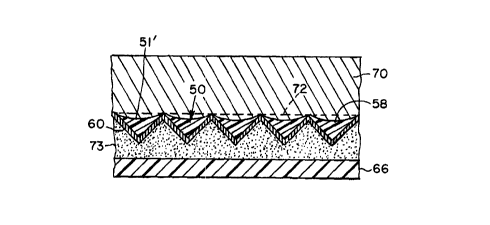
The resulting base face 51'' of the prisms 58 has a
concave surface, caused by shrinkage of the prism
material during curing of the acrylated epoxy oligomer
prism material and pulling down of the malleable top
film 54 slightly into the prism volume.
As shown in Fig. 4, the re:Lease layer 64 may then
be removed from adhesive 62 and the prism array 50
attached by adhesive 62 to a pe:rmanent substrate, such
as a vinyl or urethane panel or rain-ware gear 66 and a
transparent protective cover layer 70 deposited,
laminated or otherwise applied over the array 50.
optionally, the transparent cover layer can be
added as a coating or film bonded to the prism top faces
prior to attaching the assembly to the final substrate.
Note: The degree of concavity of the prism top
face is indicated by the dashed line 72 showing the
original planar face 51.
The degree of concave curvature can be controlled
by the hardness of the top film utilized. In the above
20 example a 0.9 wave concave prism front face was created
using a . 006" thick vinyl film with a 66 hardness formed
of 34~ plasticizer and 66% PVC, carried by a . 002" thick
polyester film. If the hardness of the vinyl is
adjusted to 75 (25~ plasticizer, 75~ PVC), the front
25 face will be approximately 0. 45 waves or 2,848 angstroms
(A=6328A) concave. Ideally, a concave curvature of
approximately 1,000 angstroms is desired.
In an alternative embodiment as shown in Fig. 5,
prisms 50' with curved top faces are formed as cast by
30 utilizing a belt or platen 200 in place of the top film
54 of Fig. 3C. The belt is provided with randomly
located micro convex or concave surfaces 202 on the belt
face abutting the array of prisms 50' being cast in a
mold on a drum as in Figs. 3A, 3B. This belt or platen
35 iS laminated against the oligomer filled prism mold 204
as in Fig. 3B as the rollers (not shown) pass in the
CA 02266379 1999-03-22
WO98/12581 PCT~S97/1~993
direction of the arrows. The oligomer is cured by W
radiation from source 206 causing concave or convex
surfaces to be formed on the ba~se surfaces of the prisms
50'. The cast and cured prism array is then removed
from the mold 204 with belt 200 attached thereto by a
preferential adhesive (not shown) which was previously
applied to the belt 200 on the surface abutting the
prism top face. An optional ca:rrier film 210 is adhered
to belt 200 by release layer 212 which may be removed
leaving the belt 200 attached to the array of prisms 50.
As in Fig. 3D; the exposed prism facets are coated with
a reflective material and a temporary release layer
applied thereto by an adhesive not shown. The belt 200
may then be peeled away from the prism array leaving a
reflective prism array with arcl~ate base faces attached
to a release layer similar to the structure shown in
Fig. 3E.
Some of the randomly positioned lens surfaces may
not align with the center of the prisms' effective
apertures, but sufficient numbers should do so to create
the desired light distribution improvement.
Without base face curvature, the diffraction
pattern at 15 feet from a .0055 inch pitch prism will be
as shown in Fig. 2, except that the curvature maximum
will be larger in diameter than the surrounding
maximums.
With a 0.9 wave base face curvature in accordance
with the invention and a 0.0055 inch pitch size prism,
the diffraction pattern at 15 feet for an array formed
as in Figs. 3A-3E will be as shown in Fig. 6. Note that
the central maximum in Fig. 4 has become six spread
maxima in Fig. 6.
With a 0.45 wave base face curvature on the same
size prism, the diffraction pattern is as shown in
Fig. 7.
CA 02266379 1999-03-22
WO98112~1 PCT~S97/15993
-10-
With a 0.16 wave base face curvature on the same
size prism, the diffraction patt:ern will be near ideal
and is shown in Fig. 8.
Note how the spread in the central maxima in six
directions has enlarged the light distribution to form a
near Gaussian distribution of the diffracted light.
A greater curvature of the prism base face can be
allowed if the prism is to be over coated with a
protective film, such as film 70 in Fig. 4, which has an
index of refraction different from the index of the
prisms. For example, if the over coat film 70 has an
index of refraction of 1.58, ancl the prisms 58 have an
index of refraction of 1.53, the curvature of the prism
face will need to be about .48 waves or 3,000 angstroms
to achieve the ideal retroreflected light distribution.
A coating or an embossing roll to apply the correct
lenslet surface to the top film can be made using the
following method as shown in Figs. 9 and 10.
First: The exposed prism concave top faces are
formed as described above by ut.lizing a vinyl film 90
carried on a polyester film 92 and adhered by tie-
coating adhesive 94 to an array of corner-cube
microprisms 96. The microprism side of the assembly is
bonded to a rigid plastic plate 68 (Fig. 9). Next the
top film is stripped off to expose the resulting concave
top face of the prism (Fig. 10) The hardness of the
vinyl 90 is selected to achieve the desired amount of
concave curvature on the prism lop face.
Second: A conductive coating 98, such as Al, Ag,
Au, Ni, is bonded to the concave top faces of the
prisms. An electroform replica is made of the
microconcave surfaces that may be used to coat onto or
emboss the pattern into films. The tool created in this
step may be used to emboss thermoplastic pieces creating
the pattern. A number of embos~,ed plastic pieces or
electroformed pieces are assembled together to create a
CA 02266379 1999-03-22
W O 98tl2581 PCTnUS97/15993
--11-
large part to electroform a large tool or create a
surface that can be wrapped around an embossing or
coating drum.
In the first step above the original film could be
bonded to an elastomeric mounting surface and after the
vinyl and polyester films are removed, the elastomeric
film could be formed around a mandrel and used to
electroform a cylinder with the micro surface pattern on
the inside of the cylinder. The cylinder could then be
used to electroform a final coating or embossing roll.
The elastomeric film could be stretched when applied to
the mandrel in the first step tc create spacing between
the concave top faces of the prisms. In this case the
adhesive used would need to be inert to the metalizing
process required to form the conductive coating prior to
electroforming.
Another way to create the spacing or random spacing
is to selectively (pattern) coat an oligomer on the
concave bases of the prism faces, filling some of the
prism faces and leaving some open (with a concave
surface). Then metallize and follow with electro-
forming a metal mold, and finally creating an embossing
drum.
In another alternative (as shown in Fig. 11), the
transparent cover layer can be m,odified to be adhered by
a patterned adhesive 100. The ~risms 50A that intersect
with the adhesive 100 are wetted out by the adhesive and
will retroreflect like normal because the curvature of
the prism base faces is eliminated and replaced by the
material of the adhesive which has the same index of
refraction as the prisms. The index of refraction of
the adhesive is within 0.5~ of the index of refraction
of the prisms. The prisms 50B left with the front face
exposed to air 110 will retroreflect at a wider
observation angle as a result of the top face curvature.
CA 02266379 l999-03-22
W O 98/12581 rCT~US97tlS993
-12-
The resulting retroreflected liqht distribution will be
a combination of Fig. 2 and Figs. 6, 7 and 8.
As a further alternative, t:he top film or coating
302 (Fig. 13) may be loaded with W light absorbers to
extend the useful outdoor life of the product by
reducing the deleterious effects of W light on the
underlying retroreflective materials. An example of
such a vinyl film is Renolit H068 W film. Heretofore
such absorbers were added by an additional film or
coating 4 (as in Fig. 1) applied at the final stages of
assembly. By incorporating the W absorbers in the top
film 302, the additional step and thickness of the prio~
art film or coating 4 (Fig. 1) is obviated.
Theoretically, by this method a retroreflective product
15 310 that is only . 003 inch thic~ can be produced as
compared to prior art products that range from .006 to
.015 inch thick. Additionally, before applying the top
film, a white crosshatch width 300 of material, such as
a white aliphatic urethane (the whiteness achieved by
TiO2 additive), can be formed over portions of the
curved prism top faces 51 as shown in Fig. 15 to enhance
the whiteness or CAP Y of the sheeting.
The top film 302 then can be bonded onto the
pattern 300 and the remaining exposed prism top faces
with an adhesive (not shown) that fully covers the
surface or with a pattern of adhesive (not shown) that
leaves some of the prism top faces 302 exposed to an air
boundary between the prism top ~-ace 502 and the top film
302.
In a further embodiment (not shown), a top film 302
that has a variation in index o:E refraction from point
to point may be employed. The variation in the index of
refraction will cause the retroreflected light to be
spread by differing amounts dependent on the index
variation magnitude.
CA 02266379 1999-03-22
WO98112~1 PCT~$97/15993
Having thus described a few particular embodiments
of the invention, various alterations, modifications and
improvements will readily occur to those skilled in the
art. Such alterations, modifications and improvements
as are made obvious by this disclosure are intended to
be part of this description though not expressly stated
herein, and are intended to be within the spirit and
scope of the invention. Accordingly, the foregoing
description is by way of example only, and not limiting.
The invention is limited only as defined in the
following claims and equivalents thereto.
For example, while the invention has so far been
described in connection with a concave curvature base
face and metallic coated reflective prisms, other
curvature shapes are contemplated for producing
different optical effects, such as, convex, or prismatic
base faces which could be made by embossing a shape or
texture into the top film, prior to casting the prisms.
Suitable alternative top films with appropriate
hardness and malleability may include, for example, not
only vinyl, but also urethane, Folyethylene or
polypropylene. Likewise, appropriate prism material
includes not only acrylic epoxy, but also may comprise
any light transparent polymer in which the hardness can
be varied, such as vinyls urethanes, polypropylenes and
polyethylenes. A preferred temperature range for curing
acrylic epoxy with W light is 40~C to 80~C, dependent
on processing speeds.
The present invention is applicable to microprism
sheeting in which the center to center spacing of the
prisms is about .0005 inch to 0.025 inch, and preferably
.003 inch to .008 inch. As will be appreciated, the
height of the prisms will be dictated by the center to
center spacing since the prisms are typically
orthogonal.
CA 02266379 1999-03-22
W O 98/12S81 PCTrUS97/15993
The prism side faces are conventionally all
provided with a planar configuration. However, an
arcuate configuration on all faces will produce a
beneficial result with even greater uniformity.
The prisms may also be tilted at a tilt angle
(angle between the prism axis and optical axis). The
tilt should be within the range of 1~-10~, and is
preferably 3~-8~.
Lastly, some non orthogonality in the intersections
of the prism faces may be tolerated, but should be
limited to a deviation of 0.2~ and is preferably about
O.1~.
The body portion of the sheeting will generally
have a thickness sufficient to provide structural
integrity for the sheeting, i.e., at least 0.005 inch.
Generally, it will fall within the range of 0.002-0.1
inch. If so desired, it may comprise a laminate of two
or more layers depending upon the method of fabrication,
the resins selected, and other characteristics desired
for the retroreflective sheetinq.
The microprism sheeting is conveniently formed by
casting prisms upon a film surface functioning as the
body, or by embossing a preformed sheet, or by casting
both body and prisms concurrently. Generally, the
resins employed for such cast microprism sheeting are
cross-linkable thermoset formulations, and desirably
these resins provide flexibility, light stability, and
good weathering characteristics. In some instances, the
front face of the retroreflective sheeting may be
provided with a protective coating such as by
application of a lacquer or other coating material.
Other suitable resins for the retroreflective sheeting
include vinyl chloride polymers, polyesters,
polycarbonates, methyl methacrylate polymers,
polyurethanes and acrylated urethanes.
CA 02266379 1999-03-22
WO98/12581 PCT~S97/15993
To protect a relatively thin body member during
processing, a relatively rigid carrier may be
temporarily bonded thereto, and it will generally have a
thickness of .001 inch to .004 :inch. The adhesive used
to effect the temporary bonding and which preferentially
adheres to the carrier is conveniently a silicone
adhesive applied to a thickness of about 0.00025 to
0.0005 inch. When ultraviolet curing of the resin in
the prisms is employed (as preferred herein), the
adhesive must be transparent to the light rays.
Although various resins may be employed for such a
carrier, polyesters, and particularly polyethylene
terephthalate, are desirably employed because of their
toughness and relative resistance to processing
conditions. As with the adhesive, the carrier should be
transparent to the ultraviolet radiation used to effect
curing. Moreover, the surface of the carrier may be
treated to enhance the preferenlial adhesion of the
adhesive to the surface of the carrier.
A particularly advantageous method for making such
cast retroreflective sheeting is described and claimed
in previously cited U.S. Letters Pat. No. 3,689,346
granted September 5, 1972 to W.]?. Rowland in which the
cube corner formations are cast in a cooperatively
configured mold providing microprism recesses and are
bonded to sheeting which is app:Lied thereover to provide
a composite structure in which lhe cube corner
formations project from the one surface of the sheeting.
Another method for fabricaling such microprism
sheeting is described in Rowland U.S. Letters Patent No.
4,244,683 granted January 13, 1'381 (also incorporated
herein it its entirety by reference) in which the cube
corner formations are produced by embossing a length of
sheeting in suitable embossing apparatus with molds
having precisely formed microprism cavities and in a
manner which effectively avoids entrapment of air.
CA 02266379 1999-03-22
WO98/12S81 rCT~S97/15993
-16-
The latter method has been used for forming
sheeting of acrylic and polycarbonate resins while the
former method has proven highly advantageous for forming
retroreflective sheeting from polyvinyl chloride resins
and, more recently, polyester body members with prisms
of various resin formulations including acrylated epoxy
oligomers.
It is customary to provide a backing sheet behind
the microprisms so as to protect: them and to provide a
smooth surface for application of the structure to
support surfaces. To effect larnination of such a
backing sheet to the retroreflective sheeting,
adhesives, ultrasonic and radio frequency welding have
generally been employed.
As previously described, the reflective interface
for the prisms may be provided by a reflective coating
or by an air interface. In the preferred embodiment of
the present invention, a refleclive coating is provided
upon the surfaces of the microp:risms, and such
reflective coatings have most commonly been vacuum
metallized aluminum or other specular metal deposits,
although metallic lacquers and other specular coating
materials have also been used.
A colored coating material may be provided over
some of the prisms to provide a daytime coloration.
Such a material may be colored lacquer applied to the
surface of the sheeting, a colored adhesive, or any
other colored deposit which will coat the prism
surfaces. Conveniently, a colored adhesive is employed
since this will enable bonding of the backing material
there to.
A retroreflective material utilizing some prisms
which have reflective air interfaces and others which
utilize a reflective coating offers some advantages and
is described in detail in Martin U.S. Letters Patent No.
4,801,193 granted January 31, 1989 (the teachings of
CA 02266379 1999-03-22
W O g8/12581 PCTnUS97/15993
which are incorporated in their entirety by reference).
If so desired, retroreflective sheeting may be produced
by applying the backing material to a partially
metallized material so as to maintain the air interface
in the uncoated areas.
To produce a sheeting which exhibits a daytime
coloration, a colored coating may be applied over the
entire area of a partially metalized surface so that it
directly coats the unmetallized prisms. Thereafter, the
backing material is applied. In an alternate colored
embodiment using an air interface for retroreflection, a
colored adhesive is applied in a pattern to the prism
surface and to a depth greater than the height of the
prisms. When the backing element is laminated thereto,
it is spaced from the prisms by the adhesive and this
provides an air interface about the uncoated prisms.
The backing material may be any suitable material.
For flexibility, it should comprise a woven or laid
fabric, or a flexible, durable p~lymeric material.
Suitable resins include polyethylene, polypropylene,
polyurethanes, acrylated polyurethanes,
polyvinylchloride and ethylene/vinyl acetate copolymers.
Polyester and urethane fabrics may be employed as well
as those of natural fibers such as cotton. Flame
retardants may be incorporated in the adhesives as well
as in the fabric or resin backing to impart flame
retardance to the retroreflective material.
Although other metals may be used to provide a
specular metal deposit including silver, rhodium,
copper, gold, tin, zinc and palladium, the preferred and
most economical processes utilize aluminum vacuum
deposition. Other deposition techniques include
electroless plating, electroplating, ion deposition and
sputter coating.
The step of adhering the backing to the
retroreflective sheeting may simply involve passing the
CA 02266379 1999-03-22
WO98/12581 PCT~S97/15993
adhesively coated retroreflective sheeting through the
nip of a pair of rolls together with the backing
material to apply the necessary pressure to effect
adhesion. If a heat activatable adhesive is employed,
the retroreflective sheeting may be subjected to
preheating prior to passage through the rolls, or the
rolls may be heated to achieve the necessary activation.
However, it is also practicable to employ radio
frequency or ultrasonic welding and other techniques to
bond the backing material to the retroreflective
sheeting by the material of the backing material itself
when it is thermoplastic.
To provide a coloration to the retroreflective
panel at night, a dye may be incorporated in the resin
used to form the body member, and even the prisms. As
an alternative to a dye and as an effective necessity in
some resin systems, the coloration may be provided as a
finely divided pigment which is well dispersed; however,
some loss in retroreflectivity will occur as the result
of refraction by pigment particles which are directly in
the path of light rays.
An air interface may be used in place of the
reflective coating 60 if the array is interconnected at
the prism edges and an adhesive pattern is used to hold
the structure down as the top film 54 is removed.
In the embodiment of Fig. 12, the heat shrinkable
prism mold material is directly cured in the mold as the
mold 204 is removed relative to the heat source 206
producing cured prisms 50B" with curved base surfaces
from uncurved and uncured prisms 50". An array of such
prisms may then be attached to suitable sheeting in the
well known manner.
Thus, it can be seen from the foregoing detailed
description and attached drawings that the present
invention provides a retroreflective microprism material
which exhibits a desirably controlled spread of the
CA 02266379 1999-03-22
PCTnUS97115993
W O 98/12581
-19 -
retroreflected light energy with:Ln a narrow cone and
which is operative to retroreflect light impinging
thereon at an entrance angle which deviates from normal.
The retroreflected light energy :is thus concentrated and
reasonably uniformly dispersed about a reasonably narrow
divergent cone to facilitate viewing by persons
displaced from the illuminating light source.