Note: Descriptions are shown in the official language in which they were submitted.
CA 02266443 1999-03-22
P1146E -1- 3. M~irz 1999
TRANSMISSION MEANS FOR TRANSMIITING PUSHING FORCES
The invention is in the field of force l~ on devices and concerns a
tr~ncmicciQn means accor-ling to the generic part of the independent claim
and serving for transmitting pushing forces. The inventive tr~ncmiccion means
ic d~cien~d for pushing operation (i.e. pressure loadable) and for force
5 tr~ncmiccion on a path which is selectable within broad lirnits, i.e. also
cont~ining freely selectable curves.
According to the state of the art, pressure loadable tr~ncmission means
10 applicable for curved tr~ncmicsion paths as well as for straight trancmission paths consist of e.g. a series of tr~ncmiccion members guided in a
corresponding guide ch~nnel, the members being spherical or dumbbell-
shaped. For a line of dumbbell-shaped members to be curveable in all
directions, the contact faces of the members are convex as is the ciase with
15 spherical members. This means that in both cases the tr~ncmicsion nlembers
are in contact with each other in a very small area (theoretically in one point)whether being arranged in a straight line or in a curved line. The whole force
is tr~ncmitted via this contact point. Therefore, a line of such transrrussion
members, even a straight line is very unstable regarding buckling. Due to
20 buckling, the members effect radial forces on the guide means even on a
straight tr~ncmiccion path resulting in a considerabîe loss of force trough
CA 02266443 1999-03-22
P1146E - 2 -
friction and in the need for a correspondingly strong design of the guide
means.
In the publication US-3518051, a force trancmiscion means of the named type
having spheres as force tr~n.cmiccinn members is described. Publication US-
3968861 describes a force tr~ncmiccion means of a similar type with dumbbell-
shaped tr~ncmic.cinn members. These members have convex contact faces and
for reducing friction, comprise rollers rolling on rolling surfaces of the guide
means.
The publications CH-646762 (or US-4397145) and CH-656683 of the same
applicant describe force tr~ncmicsion means in the form of chains which are
p,essurc or tension loadable and which comprise mutually connected
~ n~ ;scion members of a sllbst~n~i~lly spherical forrn. Such chains also
buckle easily in straight-lined pushed operation and therefore, must b~ guided
correspondingly.
The object of the invention is to create a tr~nsmicsion means for transmittine
pushing forces over freely selectable paths, i.e. curved or straight paths, which
tr~ncmicsion means substantially consists of a line of tr~ncmicsion rnembers
arranged in a guide channel. The inventive force tr~ncmission means is,
compared to known, similar means, to be able to be operated more efficiently,
i.e. with smaller loss of force. The force tr~nsmiccion means is, all the same,
to be producible in a simple way also when relatively small and it is to be
driveable with known driving means such as e.g. cogwheels, worrn gears or
hydraulic or pneurnatic cylinders.
CA 02266443 1999-03-22
,
P1146E - 3
This object is achieved by the force l~ "~;csion means as defined in the
patent clairns.
S The inventive force tr~ncmiccion means achieves the above object using
tr~ncmicsirn members which, when arranged in a straight line and pressed
against each other forrn a kind of bar which is considerably more resistant to
buckling than the lines of spheres or of dumbbell-shaped members with
convex contact faces as described abo~ve. Due to their resict~n~e to buckling,
the members of such a bar cause ~ friction on the guid~nse as long as
they are arranged in a straight line. This does not only reduce the necessary
operation energy but also leads to less costly guide channels concerning
loadability and precision whereby in specific areas operation can even be
possible without guide ch~nnel
The hlvelllive force tr~ncmi~cion means substantially consists of a line of
tr~ncmiccion members and a guide channel in which the members are moved
by a drive. The faces by which the members are in contact with each other
are de~ign~d such that the members, in coaxial orientation, form a buckling
resistant bar, i.e. the faces are designedl such that
- in a straight line of members, two neighboring members contact each
other in a contact area (not in a contact point), whereby the contact area
has no spherical syrnmetry (no ball and socket joint), extends as far as
possible away from the member axis and is formed such that the resultant
of the tr~ncmi~ted force lies on the axis of each member (buckling
rc;,is~all~ bar of members);
30 - that a force acting on a straight line of members is advantageously
transmitted from one member to the neighboring member mainly in
-
CA 02266443 1999-03-22
.
P1146E - 4 ~
radially outer regions of the contact area (further stabilization of the
buckling stable bar of elements),
- that on being arranged in contact with each other, the members are
centered and kept in a coaxial relationship (prevention of buckling
promoting, eccentric force tr~ncmission),
- that on dislocation of the members from a straight line, the members are
pivoted relative to each other i n a guided manner (maintaining the
centered arrangement) and
- that advantageously also in a curved line, a force is transmitted from one
member to the next one not via a touching point only.
Of the two contact faces of two neighboring members Eacing each other in a
line of members of the inventive force tr~ncmicsion means, one comprises a
ring-shaped ridge in a radially outer area, the other one a corresponding ring-
shaped groove or at least half groove. Thereby, ridge and groo~e have
20 m~t~hed cross sections with a circular arch profile at least in the region of the
top of the ridge and of the base of the groove (ridge: convex arch; groove:
concave arch). This means that the ridlge lies in the groove when the members
are in a coaxial arrangement and there is a contact area between them. It
further means that on pivoting the rnembers out of a coaxial position, this
~5 movement is guided due to the fact that the ridge pivots inside the grc,ove.
If the matched ring-shapcd grooves ;md ridges are circular it is possible to
pivot the tr~ncmiscion members in any desired direction. In such a case, the
30 contact area between two members being constituted by at least part of the
groove or ridge surface in a coaxial arrangement, is reduced to a corltact line
CA 02266443 1999-03-22
,
P1146E - 5 -
running perpendicular to the groove and ridge when the members are pivoted.
If the ring-shaped grooves and ridges have the form of polygons the possible
pivoting directions are restricted to directions perpendicular to the polygon
sides, whereby in the pivoted positioIl a contact surface between ridge and
S groove is m~in~inçd along one polygon side.
The grooves and corresponding ridges and/or the centers of the faces are
advantageously desi~n~d such that the centers of the faces of two coaxially
10 arranged members are not in contact with each other, i.e. that no ~orce is
lldns~ ed via the center.
The groove-and-ridge-form of the contact faces acts in a centering manner.
15 The ll;.nc",i~ion members of the inventive transmission means are pivotable
in relation to each other in any direction (circular groove and ridge) or in a
plurality of predetermined directions ~polygon-shaped groove and rid~e) and
still, when in a straight line, the members transmit a force like a bar, i.e. the
line of members shows considerable resistance to buckling. Due to shifting the
20 load to radially outer regions of the faces, the resistance to buckling is
additionally increased. Due to the circular arch profile of the ridge top and
the groove base, a guided pivoting movement of two neighboring members is
made possible in which movement the members are m~int~ined centered.
Two pivoted members are in contact along at least a contact line as opposed
25 to a contact point between two spheres or two spherical faces.
The guide channel of the inventive force tr~ncmicsion means takes up the
force in curved regions. In straight regions, however, it merely serves as a trap
30 for the tr~ncmiccion members and possibly for taking up external radial forces
acting on the trancmiscion members. As a straight line of members of the
CA 02266443 1999-03-22
P1146E - 6
illvenlive force tr~nsmiCcion means acts like a pressure loaded bar, the guidingfim-~tiQn of the guide channel becomes virtually Imnecçc5~ry in such areas and
the channel can be designed correspondingly.
The tr:lncmiscion members of the inventive force tr~ncmiccion means can,
depending on the application, be totally independent of each other or they
can be mutually connected. Corresponding connection means are to be
d~sign~d to be flexible in a manner that pivoting of the members in relation
10 to each other is possible. The connection means can at the same time have an
additional, centering function and/or a retroactive function, i.e. be clesigned
such that they force the members back into a coaxial orientation.
15 A few exemplified embodiments of the inventive force tr~ncmicsion means are
described in more detail in connection with the following Figures, whereby
Figure 1 shows an exemplified embodiment of the inventive force
trancmission means partly sectioned parallel to the axis of the guide channel;
Figure 2 shows an enlarged longitudinal section through the contact area
between two neighboring tr~ncmi~cion members of an inventive force
tr~nsmicsion means which are shown arranged coaxially (in unbroken lines)
and pivoted in relation to each other (in broken lines);
Figures 3 and 4 show two exemplified applications of the inventi~e force
tr~ncmicsion means;
Figure S shows ~ cross section through an i~l~e~ c force tr~ncmiccion means
30 in the region of a drive;
.
CA 02266443 1999-03-22
P1146E - 7 -
Figure 6 shows tr~ncmiccion members of an inventive force tr~ncmicciQn
means which comprise polygon-shaped faces;
Figures 7 and 8 show cross sections through an inventive force tr~n~miccion
5 means with members substantially according to Figure 6.
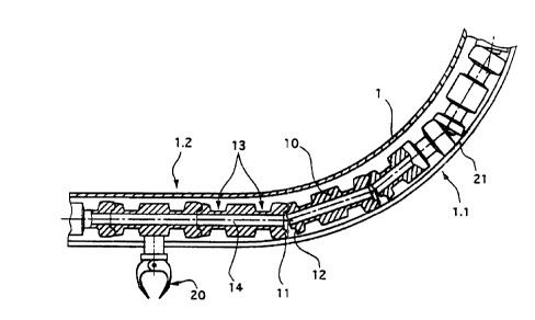
Figure 1 shows a part of an exemplified embodiment of the inventive force
tr~ncmicsion means. A guide channel 1 is shown with a curved and a straight
10 region (1.1 or 1.2 respectively). The guide channel is sectioned along its axis.
In the guide channel 1 a line of trancmic~ion members 10 is arranged and
shown partly in section along the axis.
15 The ~ .icsion members 10 comprise ac. described above two contact faces
each, one being equipped with a ring-shaped circular ridge 11 and tlle other
one being equipped with a corresponding ring-shaped circular groove 12. In
order to allow mutual pivoting of the members around an axis right-angled to
the axis of the members the outer wall of the groove is reduced. Of course, it
20 is possible also to form a line of alternating members the ones being equipped
with grooves on both contact faces the other ones being equipped with ridges
on both contact faces.
25 The design of the tr~ncmicsiorl members 10 between the faces is not relevant
to the invention. If e.g. the members are to be driven with a cog-wheel or a
similar driving means they must have a form which can be grippecl by the
driving means, e.g. comprising one or two locations (denominated ~ith 13)
having a reduced cross section. If the members are to be movable around
30 curves being relatively tight in relation to the member length, the rnembers
CA 02266443 1999-03-22
P1146E - 8 -
are advantageously designed in the shape of dumbbells with substantially
spherical ends.
S The ~ s~"iss;on members may co~ e an axial bore 14. This displaces
force ~ sion to the radially oulter region of groove and ridge and in
addition may serve for a cable for trln.cmic~ion of electric power or electric
signals to a predetermined location on, the line of members to be loosely laid
through the line of members. Such a cable can additionally take c~ver the
10 function of a loose connection of the trsln~mission members (see also Figure
6).
As a suggestion for an exemplified application, a gripper 20 is shown arranged
15 on one of the tr~nsmi~cion members which gripper protrudes through an slot-
shaped opening 21 in the guide chalmel 1 to the outside and w~th which
gripper e.g. objects are movable along the guide channel 1.
20 Figure 1 shows clearly how the tr~nsmis~ion members forrn a stable bar where
they are arranged in a straight line (left hand part of the Figure). This is dueto the fact that at least in the region of groove and ridge positioned inside
each other the members are in contact with each other and they are held in a
stable centered position. ~t can also be seen from Figure 1 that the members
25 are displaced towards the outside of the channel in its curved region which
region of the channel must be able to take up corresponding forces. In
opposition to this the guide channel does not take over a guiding function in
the straight region 1.2 (the members clo not touch the guide channel in this
region, as shown). The guide channel is to fulfill stability requirements on the30 outside of curves only and there are hardly any requirements concerning
CA 02266443 1999-03-22
P1146E - 9
precision of the inner channel cavity in relation to the radial extension of the ;c~;on members.
S Figure 2 shows, on a larger scale, the contact region between two neighboring
tr~ncmiCcion members 10.1 and 10.2 again in a section along their a~dc A, the
tr~ncmicsion members being substantially sirnilar to those in Figure 1. Of the
m~mber 10.1, the face with the groove 12 is shown, of the member 10.2, the
face with the ridge 11. The member 10.1 is shown in unbroken lines in a
10 coaxial position in relation to the member 10.2 and in broken lines, in a
position pivoted in relation to member 10.1. The pivoting symbolized by the
arrow S is guided by the at least partly circular arch pro~ile of the cross
sections of groove and ridge. A defined pivoting axis extends through the
center of this circle. During pivoting, groove and ridge remain engaged. For
15 circular groove and ridge, their contact on pivoting is theoretically restricted
to a radial line perpen~icul~r to the pivoting axis and lies in the section plane
of Figure 2.
The tr~nsmicsion members 10.1 and 10.2 according to Figure 2 differ from the
tr~ncmiccion members according to Figure 1 in that they do not comprise an
axial bore (14). For still displacing force tr:lnsmiCcion to the radially outer
regions of the contact &ces, the ridge l1 is advantageously to be designed to
be higher than the deptb of the groove 12. Thus, contact in the central region
15 of the faces and force tr~nCmicsioniIl this central region is prevented.
Figure 3 shows an exemplified application of the inventive force transmission
mea~s. lt is a loop of a guide channel 1 closed in itself in which loop the
tr~ncmission members 10 are arranged in such a number that they touch each
other. The members lO are moved pu,hing each other in one or the other
CA 02266443 1999-03-22
P1146E - 10-
direc~ion in the guide channel 1 by means of a chain wheel 30 the cogs of
which reach into a corresponding opening in the guide channel 1 to interact
with tbe tr~ncmiccion members. The guide channel 1 can e.g. com,orise an
slot-shaped opening (21, Figure 1) extending over its whole length through
S which opening grippers arranged on~ the members protrude outward (20,
Figure 1) for moving objects around the whole loop, through part of the loop
or to and fro over part of the loop.
10 The charmel loop of Figure 3 consists of two straight parts connected by two
curved parts, all parts being arranged in a plain. Obviously, the loop can have
any form~ i.e. it is not a condition for it to be arranged in a plain.
15 Figure 4 shows a further exemplified application of the inventive force trans-
mission means. The guide channel is not closed in itself and comprises
between two curved regions 1.1, a straight region 1.2. At the two ends of the
straight part, two mutually coupled drive wheels 30.1 and 30.2 are provided
for acdng on the line of trancmission members arranged in the channel.
The force trancmiscion means according to Figure 4 e.g. serves for di~placing
a part 31 of the device (shown very diagramm~ lly) or several such parts to
and fro. The total length of the guide channel 1 and the length of the line of
25 tr~ncmiccion members arranged in the channel is designed such that the line
reaches at least from one drive wheel to the other one (30.1 or 30.2
respectively) when the part of the d,evice is in one of the predetermined
extreme positions. The curved parts 1.1 of the guide channel are orientated
such that tr~ncmicsion members 10 located therein are driven by gravity
30 towards the straight part 1.2. Thereby! the members are not exposed to any
CA 02266443 1999-03-22
P1146E - 11-
."ic~ n force, i.e. there are virtually no friction and wearin~ forces
neither on the curved channel parts nor on the straight channel part.
S Obviously, for the application shown in Figure 4 a co-respondingly driven bar
could be used instead of the line c,f tr~ncmission members. Function and
operation characteristics of the bar between the two driving wheels 30.1 and
30.2 would be exactly the same as the function of the bar formed by the
tr~nsmiscion members. The advantage of the inventive force trancmicsion
10 means compared to the bar is the curved channel ends 1.1, which constitute inparticular in the case of a long straight part a considerable amount of space
saved.
15 Figure S shows a cross section through a driving wheel 30 gripping .nto the
guide charmel and cooperating with a tr~ncmiccion member 10. A gripper 20
is arranged on the trancmission member 10 which gripper protrudes out o~ the
guide channel through a slot-shaped opening 21.
Figure 6 shows two tr~nsmiccion mernbers 10.3 pivoted in relation to each
other. In opposition to the tr~nsmicsion members of Figures 1 and 2 the
contact faces of the members are square and comprise a groove 12 or a ridge
11 respectively having the ~orm of a quadrangular ring, whereby groove and
25 ridge have e.g. the same cross section as the ones shown in Figure 2.
Compared to trancmiccion members with circular grooves or ridges
respectively, these members 10.3 can only be pivoted in a controlled manner
in four directions at right angles to each other. For more pivoting directions,
hexagonal, octagonal or generally polygon-shaped rings of ridge and groove
30 are possible.
CA 02266443 1999-03-22
-
P1146E - 12-
In Figure 6, a cable 16 laid through the axial bores of the members is also
shown as an exemplified, loose connection means for loosely connecting the
tr~ncmiCcion members.
Grooves and ridges on contact faces of tr~ncmission means designed to be
polygon-shaped must not necessarily form a continnous ring. They can e.g. be
hlle,lupted at the edges of the polygol1.
Figures 7 and 8 show in cross section, tr~ncmissiQn members 10.3 substantially
according to Figure 6 positioned in al guide channel 1.3 or 1.4 respectively.
The Figures show that the trancmiccilm members 10.3 having a square face
are applicable in square guide ch~nne!s (1.3) as well as in circular ones (1.4).15 In a guide channel with a round cross section it is advantageous to provide
means for m~int~inine the rotational alignrnent of the transmiccion members.