Language selection

Search

Patent 2266494 Summary

Third-party information liability

Some of the information on this Web page has been provided by external sources. The Government of Canada is not responsible for the accuracy, reliability or currency of the information supplied by external sources. Users wishing to rely upon this information should consult directly with the source of the information. Content provided by external sources is not subject to official languages, privacy and accessibility requirements.

Claims and Abstract availability

Any discrepancies in the text and image of the Claims and Abstract are due to differing posting times. Text of the Claims and Abstract are posted:

  • At the time the application is open to public inspection;
  • At the time of issue of the patent (grant).
(12) Patent Application: (11) CA 2266494
(54) English Title: COUPLING PIECE FOR USE AT SIMULTANEOUS EARTH AND/OR ROCK DRILLING WITH AN UPPER ROTARY PERCUSSION DEVICE AND A LOWER PERCUSSION DEVICE
(54) French Title: PIECE D'ACCOUPLEMENT UTILE DANS LE FORAGE SIMULTANE TERRE ET/OU ROCHE EFFECTUE AU MOYEN D'UN DISPOSITIF DE PERCUSSION ROTATIF SUPERIEUR ET D'UN DISPOSITIF DE PERCUSSION ROTATIF INFERIEUR
Status: Deemed Abandoned and Beyond the Period of Reinstatement - Pending Response to Notice of Disregarded Communication
Bibliographic Data
(51) International Patent Classification (IPC):
  • E21B 06/00 (2006.01)
  • E21B 04/20 (2006.01)
  • E21B 17/03 (2006.01)
  • E21B 19/086 (2006.01)
  • E21B 21/02 (2006.01)
  • E21B 44/00 (2006.01)
(72) Inventors :
  • BORG, TOMAS (Sweden)
(73) Owners :
  • ATLAS COPCO CRAELIUS AB
(71) Applicants :
  • ATLAS COPCO CRAELIUS AB (Sweden)
(74) Agent: SMART & BIGGAR LP
(74) Associate agent:
(45) Issued:
(86) PCT Filing Date: 1997-08-25
(87) Open to Public Inspection: 1998-03-26
Availability of licence: N/A
Dedicated to the Public: N/A
(25) Language of filing: English

Patent Cooperation Treaty (PCT): Yes
(86) PCT Filing Number: PCT/SE1997/001398
(87) International Publication Number: SE1997001398
(85) National Entry: 1999-03-18

(30) Application Priority Data:
Application No. Country/Territory Date
9603413-7 (Sweden) 1996-09-19

Abstracts

English Abstract


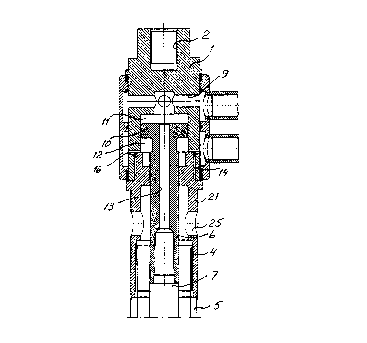
The coupling piece comprises a first connection (2) for connection of an upper
rotary percussion device (3) and a second connection (4) for connection of a
drill tube string (5) provided with an annular drill bit (23). The coupling
piece comprises a first chamber (11) and a second chamber (12) separated by a
piston (10). The pressure in the first chamber (11) is used to supply a lower
percussion device (8) connected to a third connection (6) associated with the
coupling piece with driving medium and for feeding the lower percussion device
(8) toward a ground (15). The pressure in the second chamber (12) is used to
decrease the force between the lower percussion device (8) and the ground (15)
when further drill string elements are added to the drill string (7) of which
the lower percussion device (8) forms a part.


French Abstract

Cette pièce d'accouplement, utile dans le forage simultané terre et/ou roche effectué au moyen d'un dispositif de percussion rotatif supérieur et d'un dispositif de percussion rotatif inférieur, comprend un premier raccord (2) destiné à relier un dispositif de percussion rotatif supérieur (3), ainsi qu'un second raccord (4) destiné à relier un train de tiges de forage (5) pourvu d'un trépan annulaire (23). La pièce d'accouplement comprend une première (11) et une seconde (12) chambre, séparées par un piston (10). On utilise la pression de la première chambre (11) pour alimenter en milieu d'entraînement un dispositif de percussion inférieur (8), relié à un troisième raccord (6) associé à la pièce d'accouplement, et pour pousser le dispositif de percussion inférieur (8) vers le sol (15). On utilise la pression de la seconde chambre (12) pour diminuer la force entre le dispositif de percussion inférieur (8) et le sol (15) lorsque l'on ajoute des éléments supplémentaires de tiges au train de tiges (7) dont le dispositif de percussion inférieur (8) fait partie.

Claims

Note: Claims are shown in the official language in which they were submitted.

Claim:
1. Coupling piece for use at simultaneous earth and/or rock drilling with an
upper rotary percussion device and a lower percussion device comprising a housing (1,21),
a first connection (2) on said housing (1,21) for connection of an upper rotary percussion
device (3), a second connection (4) on said housing (1,21) for connection of a drill tube
string (5), a third connection (6) associated with said houing (1,21) for connection of a drill
string (7) comprising a lower percussion device (8), and a first channel (9) arranged in said
housing (1,21) for supply of driving medium to said lower percussion device (8),characterized in that said third connection (6) is connected with a piston (10)
movable in said housing (1,21), that said piston is arranged between a first chamber (11)
and a second chamber (12), that said first channel (9) is connected with said first chamber
(11), that said piston (10) comprises a second channel (13) for transport of driving medium
from said first chamber (11) to said lower percussion device (8), that pressurization of said
first chamber (11) causes displacement of said lower percussion device (8) toward a ground
(15) for drilling and that said housing (1,21) comprises a third channel (16) for supply of
pressure flluid to said second chamber (12), and that pressurization of said second chamber
(12) causes a decrease of the force between said lower percussion device (8) and said
ground (15).

Description

Note: Descriptions are shown in the official language in which they were submitted.


CA 02266494 1999-03-18
Wo 98/12410 PCT/SE97l01398
I
Couplin~ piece for use at simultaneous earth and/or rock drilling with an upper rotary
percussion device and a lower percussion device
~ The present invention relates to a coupling piece Wit]l damping function for simultaneous
earth and/or rock drilling with an upper rotary percussion device and a lower percussion
devlce.
In a previously known drilling device, see US-A 5 355 966, for simultaneous drilling with
an upper rotary percussion device and a lower percussion device the feed force on the drill
tube string and on the lower percussion device is achieved through displacement of the
upper rotary percussion device towards the ground. A drawback with this sdlution is that
drilling cannot occur optimally since one cannot control the feed force on the upper rotary
percussion device and on the lower percussion device independent of each other for
adaption of the drilling to local variations in the ground conditions.
The present invention, which is defined in the appended claim, aims at making it possible
to drill simultaneously with an upper rotary percussion device and a lower percussion
device with optimal use of feed force and impact energy at the same time as the lower
percussion device is not affected by the shock waves of the uppeer rotary percussion
device.
An embodiment of the invention is described below with reference to the accompanying
drawings in which fig 1 shows a drilling device in which the invention is a part. Fig 2
shows a section through a coupling piece according to the invention.
The drilling device shown on the drawings comprises a coupling piece with a housing 1,
21. The housing comprises two housing parts 1 and 21 which are connected with each
other by means of a screw joint 14. The housing part 1 is provided with a first connection 2
for connection of an upper rotary percussion device 3, in the shown example a top hammer
drilling machine. The top hamrner drilling m~elline is displaceable towards or from a
ground 15, which can be an earth and/or rock formation, by means of a feed device 22. The
. _ .. .

CA 02266494 1999-03-18
W 098/12410 PCT/SE97/01398
housing part 21 is provided with a second connection 4 for connection of a drill tube string
5. The drill tube string 5 comprises one or more drill tubes and at the front end an annular
drill bit 23. The annular drill bit 23 is fed towards the ground 15 by the feed device 22 and
is exerted to impacts by the top hammer drilling machine 3. In the housing 1, 21 a piston
10 is movably arranged between a first chamber 1 1 and a second chamber 12. A third
connection 6 is arranged on the piston 10 for connection of a drill string 7 comprising a
lower percussion device 8, in the shown example a down-the-hole drilling machine. The
drill string 7 can in addition to the down-the-hole drilling machine 8 comprise one or more
drill string elements. At the front end of the down-the-hole drilling machine a drill bit 24 is
arranged. The down-the-hole drilling machine 8 is supplied with driving medium, gas or
liquid, via a first channel 9 in the housing part l and a second channel 13 in the piston 10.
The pressure in the first chamber 11 displaces the down-the-hole drilling machine 8 and
thus its drill bit 24 toward the ground 15. The drill bit 24 is exerted to impacts by the
down-the-hole drilling machine 8. The first chamber 11 functions also as a shock absorber
between the upper rotary percussion device 3 and the drill string 7. through which the
down-the-hole drilling machine 8 is protected from harmful influence from the shock
waves from the upper rotary percussion device. The housing part I is provided with a third
channel 1~ for supply of pressure fluid, gas or liquid, to the second chamber 12.
Pressurization of the second chamber 12 is used to decrease the force between the
down-the-hole drilling machine 8, and thus its drill bit 24, and the ground 15. This makes it
possible to achieve the desired feed force on the drill bit 24 of the down-the-hole drilling
machine when further drill string elements are added to the drill string 7, without waiving
the driving medium pressure to the down-the-hole drilling machine. The driving medium to
the down-the-hole drillng machine 8 is used for flushing the drill hole. The cuttings are
therethrough transported Up~W~lldS in the space between the drill tube string 5 and the drill
string 7 and leave the drilling device through holes 25 in the housing part 21.

Representative Drawing
A single figure which represents the drawing illustrating the invention.
Administrative Status

2024-08-01:As part of the Next Generation Patents (NGP) transition, the Canadian Patents Database (CPD) now contains a more detailed Event History, which replicates the Event Log of our new back-office solution.

Please note that "Inactive:" events refers to events no longer in use in our new back-office solution.

For a clearer understanding of the status of the application/patent presented on this page, the site Disclaimer , as well as the definitions for Patent , Event History , Maintenance Fee  and Payment History  should be consulted.

Event History

Description Date
Inactive: IPC from MCD 2006-03-12
Time Limit for Reversal Expired 2000-08-25
Application Not Reinstated by Deadline 2000-08-25
Deemed Abandoned - Failure to Respond to Maintenance Fee Notice 1999-08-25
Inactive: Cover page published 1999-05-31
Inactive: First IPC assigned 1999-05-10
Inactive: Notice - National entry - No RFE 1999-04-28
Application Received - PCT 1999-04-23
Application Published (Open to Public Inspection) 1998-03-26

Abandonment History

Abandonment Date Reason Reinstatement Date
1999-08-25

Fee History

Fee Type Anniversary Year Due Date Paid Date
Basic national fee - standard 1999-03-18
Registration of a document 1999-03-18
Owners on Record

Note: Records showing the ownership history in alphabetical order.

Current Owners on Record
ATLAS COPCO CRAELIUS AB
Past Owners on Record
TOMAS BORG
Past Owners that do not appear in the "Owners on Record" listing will appear in other documentation within the application.
Documents

To view selected files, please enter reCAPTCHA code :


To view images, click a link in the Document Description column. To download the documents, select one or more checkboxes in the first column and then click the "Download Selected in PDF format (Zip Archive)" or the "Download Selected as Single PDF" button.

List of published and non-published patent-specific documents on the CPD .

If you have any difficulty accessing content, you can call the Client Service Centre at 1-866-997-1936 or send them an e-mail at CIPO Client Service Centre.


Document
Description 
Date
(yyyy-mm-dd) 
Number of pages   Size of Image (KB) 
Drawings 1999-03-17 2 65
Abstract 1999-03-17 1 69
Description 1999-03-17 2 102
Claims 1999-03-17 1 35
Representative drawing 1999-05-24 1 18
Reminder of maintenance fee due 1999-04-26 1 111
Notice of National Entry 1999-04-27 1 193
Courtesy - Certificate of registration (related document(s)) 1999-04-27 1 117
Courtesy - Abandonment Letter (Maintenance Fee) 1999-09-21 1 187
PCT 1999-03-17 8 436