Sélection de la langue

Search

Sommaire du brevet 2266494 

Énoncé de désistement de responsabilité concernant l'information provenant de tiers

Une partie des informations de ce site Web a été fournie par des sources externes. Le gouvernement du Canada n'assume aucune responsabilité concernant la précision, l'actualité ou la fiabilité des informations fournies par les sources externes. Les utilisateurs qui désirent employer cette information devraient consulter directement la source des informations. Le contenu fourni par les sources externes n'est pas assujetti aux exigences sur les langues officielles, la protection des renseignements personnels et l'accessibilité.

Disponibilité de l'Abrégé et des Revendications

L'apparition de différences dans le texte et l'image des Revendications et de l'Abrégé dépend du moment auquel le document est publié. Les textes des Revendications et de l'Abrégé sont affichés :

  • lorsque la demande peut être examinée par le public;
  • lorsque le brevet est émis (délivrance).
(12) Demande de brevet: (11) CA 2266494
(54) Titre français: PIECE D'ACCOUPLEMENT UTILE DANS LE FORAGE SIMULTANE TERRE ET/OU ROCHE EFFECTUE AU MOYEN D'UN DISPOSITIF DE PERCUSSION ROTATIF SUPERIEUR ET D'UN DISPOSITIF DE PERCUSSION ROTATIF INFERIEUR
(54) Titre anglais: COUPLING PIECE FOR USE AT SIMULTANEOUS EARTH AND/OR ROCK DRILLING WITH AN UPPER ROTARY PERCUSSION DEVICE AND A LOWER PERCUSSION DEVICE
Statut: Réputée abandonnée et au-delà du délai pour le rétablissement - en attente de la réponse à l’avis de communication rejetée
Données bibliographiques
(51) Classification internationale des brevets (CIB):
  • E21B 06/00 (2006.01)
  • E21B 04/20 (2006.01)
  • E21B 17/03 (2006.01)
  • E21B 19/086 (2006.01)
  • E21B 21/02 (2006.01)
  • E21B 44/00 (2006.01)
(72) Inventeurs :
  • BORG, TOMAS (Suède)
(73) Titulaires :
  • ATLAS COPCO CRAELIUS AB
(71) Demandeurs :
  • ATLAS COPCO CRAELIUS AB (Suède)
(74) Agent: SMART & BIGGAR LP
(74) Co-agent:
(45) Délivré:
(86) Date de dépôt PCT: 1997-08-25
(87) Mise à la disponibilité du public: 1998-03-26
Licence disponible: S.O.
Cédé au domaine public: S.O.
(25) Langue des documents déposés: Anglais

Traité de coopération en matière de brevets (PCT): Oui
(86) Numéro de la demande PCT: PCT/SE1997/001398
(87) Numéro de publication internationale PCT: SE1997001398
(85) Entrée nationale: 1999-03-18

(30) Données de priorité de la demande:
Numéro de la demande Pays / territoire Date
9603413-7 (Suède) 1996-09-19

Abrégés

Abrégé français

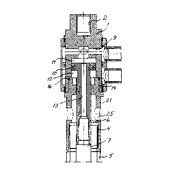
Cette pièce d'accouplement, utile dans le forage simultané terre et/ou roche effectué au moyen d'un dispositif de percussion rotatif supérieur et d'un dispositif de percussion rotatif inférieur, comprend un premier raccord (2) destiné à relier un dispositif de percussion rotatif supérieur (3), ainsi qu'un second raccord (4) destiné à relier un train de tiges de forage (5) pourvu d'un trépan annulaire (23). La pièce d'accouplement comprend une première (11) et une seconde (12) chambre, séparées par un piston (10). On utilise la pression de la première chambre (11) pour alimenter en milieu d'entraînement un dispositif de percussion inférieur (8), relié à un troisième raccord (6) associé à la pièce d'accouplement, et pour pousser le dispositif de percussion inférieur (8) vers le sol (15). On utilise la pression de la seconde chambre (12) pour diminuer la force entre le dispositif de percussion inférieur (8) et le sol (15) lorsque l'on ajoute des éléments supplémentaires de tiges au train de tiges (7) dont le dispositif de percussion inférieur (8) fait partie.


Abrégé anglais


The coupling piece comprises a first connection (2) for connection of an upper
rotary percussion device (3) and a second connection (4) for connection of a
drill tube string (5) provided with an annular drill bit (23). The coupling
piece comprises a first chamber (11) and a second chamber (12) separated by a
piston (10). The pressure in the first chamber (11) is used to supply a lower
percussion device (8) connected to a third connection (6) associated with the
coupling piece with driving medium and for feeding the lower percussion device
(8) toward a ground (15). The pressure in the second chamber (12) is used to
decrease the force between the lower percussion device (8) and the ground (15)
when further drill string elements are added to the drill string (7) of which
the lower percussion device (8) forms a part.

Revendications

Note : Les revendications sont présentées dans la langue officielle dans laquelle elles ont été soumises.


Claim:
1. Coupling piece for use at simultaneous earth and/or rock drilling with an
upper rotary percussion device and a lower percussion device comprising a housing (1,21),
a first connection (2) on said housing (1,21) for connection of an upper rotary percussion
device (3), a second connection (4) on said housing (1,21) for connection of a drill tube
string (5), a third connection (6) associated with said houing (1,21) for connection of a drill
string (7) comprising a lower percussion device (8), and a first channel (9) arranged in said
housing (1,21) for supply of driving medium to said lower percussion device (8),characterized in that said third connection (6) is connected with a piston (10)
movable in said housing (1,21), that said piston is arranged between a first chamber (11)
and a second chamber (12), that said first channel (9) is connected with said first chamber
(11), that said piston (10) comprises a second channel (13) for transport of driving medium
from said first chamber (11) to said lower percussion device (8), that pressurization of said
first chamber (11) causes displacement of said lower percussion device (8) toward a ground
(15) for drilling and that said housing (1,21) comprises a third channel (16) for supply of
pressure flluid to said second chamber (12), and that pressurization of said second chamber
(12) causes a decrease of the force between said lower percussion device (8) and said
ground (15).

Description

Note : Les descriptions sont présentées dans la langue officielle dans laquelle elles ont été soumises.


CA 02266494 1999-03-18
Wo 98/12410 PCT/SE97l01398
I
Couplin~ piece for use at simultaneous earth and/or rock drilling with an upper rotary
percussion device and a lower percussion device
~ The present invention relates to a coupling piece Wit]l damping function for simultaneous
earth and/or rock drilling with an upper rotary percussion device and a lower percussion
devlce.
In a previously known drilling device, see US-A 5 355 966, for simultaneous drilling with
an upper rotary percussion device and a lower percussion device the feed force on the drill
tube string and on the lower percussion device is achieved through displacement of the
upper rotary percussion device towards the ground. A drawback with this sdlution is that
drilling cannot occur optimally since one cannot control the feed force on the upper rotary
percussion device and on the lower percussion device independent of each other for
adaption of the drilling to local variations in the ground conditions.
The present invention, which is defined in the appended claim, aims at making it possible
to drill simultaneously with an upper rotary percussion device and a lower percussion
device with optimal use of feed force and impact energy at the same time as the lower
percussion device is not affected by the shock waves of the uppeer rotary percussion
device.
An embodiment of the invention is described below with reference to the accompanying
drawings in which fig 1 shows a drilling device in which the invention is a part. Fig 2
shows a section through a coupling piece according to the invention.
The drilling device shown on the drawings comprises a coupling piece with a housing 1,
21. The housing comprises two housing parts 1 and 21 which are connected with each
other by means of a screw joint 14. The housing part 1 is provided with a first connection 2
for connection of an upper rotary percussion device 3, in the shown example a top hammer
drilling machine. The top hamrner drilling m~elline is displaceable towards or from a
ground 15, which can be an earth and/or rock formation, by means of a feed device 22. The
. _ .. .

CA 02266494 1999-03-18
W 098/12410 PCT/SE97/01398
housing part 21 is provided with a second connection 4 for connection of a drill tube string
5. The drill tube string 5 comprises one or more drill tubes and at the front end an annular
drill bit 23. The annular drill bit 23 is fed towards the ground 15 by the feed device 22 and
is exerted to impacts by the top hammer drilling machine 3. In the housing 1, 21 a piston
10 is movably arranged between a first chamber 1 1 and a second chamber 12. A third
connection 6 is arranged on the piston 10 for connection of a drill string 7 comprising a
lower percussion device 8, in the shown example a down-the-hole drilling machine. The
drill string 7 can in addition to the down-the-hole drilling machine 8 comprise one or more
drill string elements. At the front end of the down-the-hole drilling machine a drill bit 24 is
arranged. The down-the-hole drilling machine 8 is supplied with driving medium, gas or
liquid, via a first channel 9 in the housing part l and a second channel 13 in the piston 10.
The pressure in the first chamber 11 displaces the down-the-hole drilling machine 8 and
thus its drill bit 24 toward the ground 15. The drill bit 24 is exerted to impacts by the
down-the-hole drilling machine 8. The first chamber 11 functions also as a shock absorber
between the upper rotary percussion device 3 and the drill string 7. through which the
down-the-hole drilling machine 8 is protected from harmful influence from the shock
waves from the upper rotary percussion device. The housing part I is provided with a third
channel 1~ for supply of pressure fluid, gas or liquid, to the second chamber 12.
Pressurization of the second chamber 12 is used to decrease the force between the
down-the-hole drilling machine 8, and thus its drill bit 24, and the ground 15. This makes it
possible to achieve the desired feed force on the drill bit 24 of the down-the-hole drilling
machine when further drill string elements are added to the drill string 7, without waiving
the driving medium pressure to the down-the-hole drilling machine. The driving medium to
the down-the-hole drillng machine 8 is used for flushing the drill hole. The cuttings are
therethrough transported Up~W~lldS in the space between the drill tube string 5 and the drill
string 7 and leave the drilling device through holes 25 in the housing part 21.

Dessin représentatif
Une figure unique qui représente un dessin illustrant l'invention.
États administratifs

2024-08-01 : Dans le cadre de la transition vers les Brevets de nouvelle génération (BNG), la base de données sur les brevets canadiens (BDBC) contient désormais un Historique d'événement plus détaillé, qui reproduit le Journal des événements de notre nouvelle solution interne.

Veuillez noter que les événements débutant par « Inactive : » se réfèrent à des événements qui ne sont plus utilisés dans notre nouvelle solution interne.

Pour une meilleure compréhension de l'état de la demande ou brevet qui figure sur cette page, la rubrique Mise en garde , et les descriptions de Brevet , Historique d'événement , Taxes périodiques et Historique des paiements devraient être consultées.

Historique d'événement

Description Date
Inactive : CIB de MCD 2006-03-12
Le délai pour l'annulation est expiré 2000-08-25
Demande non rétablie avant l'échéance 2000-08-25
Réputée abandonnée - omission de répondre à un avis sur les taxes pour le maintien en état 1999-08-25
Inactive : Page couverture publiée 1999-05-31
Inactive : CIB en 1re position 1999-05-10
Inactive : Notice - Entrée phase nat. - Pas de RE 1999-04-28
Demande reçue - PCT 1999-04-23
Demande publiée (accessible au public) 1998-03-26

Historique d'abandonnement

Date d'abandonnement Raison Date de rétablissement
1999-08-25

Historique des taxes

Type de taxes Anniversaire Échéance Date payée
Taxe nationale de base - générale 1999-03-18
Enregistrement d'un document 1999-03-18
Titulaires au dossier

Les titulaires actuels et antérieures au dossier sont affichés en ordre alphabétique.

Titulaires actuels au dossier
ATLAS COPCO CRAELIUS AB
Titulaires antérieures au dossier
TOMAS BORG
Les propriétaires antérieurs qui ne figurent pas dans la liste des « Propriétaires au dossier » apparaîtront dans d'autres documents au dossier.
Documents

Pour visionner les fichiers sélectionnés, entrer le code reCAPTCHA :


Pour visualiser une image, cliquer sur un lien dans la colonne description du document. Pour télécharger l'image (les images), cliquer l'une ou plusieurs cases à cocher dans la première colonne et ensuite cliquer sur le bouton "Télécharger sélection en format PDF (archive Zip)" ou le bouton "Télécharger sélection (en un fichier PDF fusionné)".

Liste des documents de brevet publiés et non publiés sur la BDBC .

Si vous avez des difficultés à accéder au contenu, veuillez communiquer avec le Centre de services à la clientèle au 1-866-997-1936, ou envoyer un courriel au Centre de service à la clientèle de l'OPIC.


Description du
Document 
Date
(aaaa-mm-jj) 
Nombre de pages   Taille de l'image (Ko) 
Dessins 1999-03-17 2 65
Abrégé 1999-03-17 1 69
Description 1999-03-17 2 102
Revendications 1999-03-17 1 35
Dessin représentatif 1999-05-24 1 18
Rappel de taxe de maintien due 1999-04-26 1 111
Avis d'entree dans la phase nationale 1999-04-27 1 193
Courtoisie - Certificat d'enregistrement (document(s) connexe(s)) 1999-04-27 1 117
Courtoisie - Lettre d'abandon (taxe de maintien en état) 1999-09-21 1 187
PCT 1999-03-17 8 436