Note: Descriptions are shown in the official language in which they were submitted.
CA 02266941 1999-03-24
TITLE OF THE INVENTION
Load-side filter arrangement for a converter circuit
arrangement
BACKGROUND OF THE INVENTION
Field of the invention
The invention relates to the field of power
electronics. It is based on a load-side filter
arrangement for a converter circuit arrangement as
claimed in the preamble of the first claim. A filter
arrangement of this generic type has already been
described in European Patent Applications
EP 0 682 401 Al and EP 0 682 402 A2.
Discussion of Background
In the documents mentioned above, an LC
low-pass filter which is possibly lossy due to
resistances is inserted between the load connections
and a load. The connections of the capacitors can
either be joined together to form a star point, or can
be connected to the positive and negative connections
of the intermediate circuit. The circuit arrangement
described in these documents are preferably used for
low-voltage applications. EP 0 318 790 also discloses a
high-pass filter for a filter arrangement for a cable
which is connected to converters.
The aim of a load-side filter is to achieve an
output voltage which is as sinusoidal as possible. One
way would be to design the filter to be as large as
possible. However, this would have a number of
important disadvantages. If the filter capacitor were
short-circuited, the relevant capacitor, and all the
others connected in parallel, would be discharged
through the short-circuit. Furthermore, the
CA 02266941 1999-03-24
- 2 -
short-circuit can result in large sudden torque changes
on the connected motor, and high overvoltages on the
motor windings and filter capacitors. As consequential
faults, other short circuits can occur, so that a large
amount of energy is suddenly released, which can result
in destruction. The greater the filter capacitance is
chosen to be, the greater is the amount of energy which
must be destroyed in a deflective filter can. In
consequence, the filter can can burst, and isolation
oil can escape and contaminate the environment.
SUMMARY OF THE INVENTION
Accordingly, one object of the invention is to
provide a novel filter arrangement for a converter
circuit arrangement, in which filter arrangement the
destructive consequences of a capacitor short circuit
can be limited to a minimum, or can be entirely
avoided.
This object is achieved by the features of the
first claim, in the case of an n-phase converter
circuit arrangement of the type mentioned initially.
The essence of the invention is thus that the
capacitors of the load-side filter are combined in at
least two n-phase capacitor groups, one capacitor group
is hard-grounded, and the other capacitor group is
grounded with a high impedance via a grounded resistor.
In the event of a short circuit in a filter capacitance
only the capacitance of the defective capacitor group
is thus lost. The other capacitors continue to see the
normal phase voltage and are thus not discharged as
long as 1 R. holds (Cf = filter capacitance,
c)=Cf
Re = grounding resistance). Furthermore, no
overvoltages occur after the capacitor short circuit,
and the motor or the load do not experience any
overvoltages, either. In principle, it is possible for
the system to continue to operate after the short
CA 02266941 2004-02-03
3
circuit. The same is true for a single-phase motor ground fault. In the event
of a
ground fault or a terminal short circuit on the motor side, the short-circuit
current is
limited, and no common-mode voltages are produced on the motor. Standard
resistors
may be used as the grounding resistor. Even in the case of a number of
parallel-
connected capacitor groups, only one grounding resistor is required, depending
on the
energy content of the capacitor groups. The capacitor groups are preferably
each
surrounded by a filter can.
According to a further broad aspect of the present invention, there is
provided
a filter arrangement which is connected to a load side of a converter circuit
arrangement. The converter circuit arrangement has n phases and comprises n
load
connections to which the filter arrangement is connected. The filter
arrangement
comprises for each load connection, at least one inductance connected in
series
between the converter circuit arrangement and the load connection. It also
comprises
at least two n-phase capacitor groups. Each group includes, for each of the
load
connections, at least one capacitor connected to the respective load
connection. The
capacitors in the first one of the at least two n-phase capacitor groups are
connected to
form a first one of the n-phase star. The star point of the first capacitor
groups is
grounded via a grounded resistor, and the capacitors in a second one of the at
least
two n-phase capacitor groups are connected to form a second star. The star
point of
the second n-phase capacitor groups is hard-grounded.
BRIEF DESCRIPTION OF THE DRAWINGS
A more complete appreciation of the invention and many of the intended
advantages thereof will be readily obtained as the same becomes better
understood by
reference to the following detailed description when considered in connection
with
the accompanying drawing, wherein:
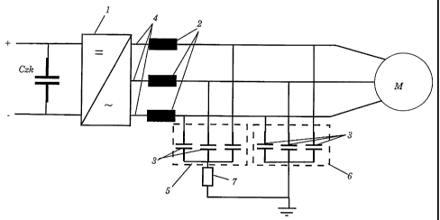
Fig. 1 shows an exemplary embodiment of the circuit design according to the
invention.
The reference numerals used in the drawings and their meanings are listed in
summarized from in the list of designations.
CA 02266941 2004-02-03
3A
DESCRIPTION OF THE PREFERRED EMBODIMENT
Referring now to the drawings, wherein like reference numerals designate
identical or corresponding parts throughout the several views, Fig. 1 shows an
exemplary embodiment of the invention. 1 denotes a power-electronic circuit
arrangement, in particular an inverter, which is fed from DC intermediate
circuit,
represented by the intermediate circuit capacitor Czk and the positive and
negative
poles +/-. The inverter 1
CA 02266941 1999-03-24
- 4 -
converts the DC voltage into an AC voltage of variable
amplitude and frequency. This AC voltage supplies a
load, for example a motor M. In order to achieve output
parameters that are as sinusoidal as possible, a
load-side filter is provided, and is connected between
the load connections 4 of the inverter 1 and the load
M. The filter is essentially formed by an LC element
with one series inductance 2 and one capacitor 3 per
phase. According to the invention, two capacitors 3 are
now provided per phase, each of which is assigned to
one of the two capacitor groups 5 and 6. Thus, in
general, at least two n-phase capacitor groups are
formed for an n-phase circuit. The two capacitor groups
5 and 6 in consequence each comprise three capacitors
which, for example, are kept immersed in oil and are
preferably surrounded by a can. The capacitors 3 in one
capacitor group are in each group connected in star.
The essence of the invention is now for the capacitors
in one capacitor group to be hard-grounded, that is to
say without any interposition of a grounding resistor,
and for those in the other capacitor group to be
grounded through a high impedance via a grounding
resistor 7.
Obviously, numerous modifications and
variations of the present invention are possible in
light of the above teachings. It is therefore to be
understood that, within the scope of the appended
claims, the invention may be practiced otherwise than
as specifically described herein.