Note: Descriptions are shown in the official language in which they were submitted.
CA 02266951 2007-06-06
74769-175
1
METHOD AND APPARATUS FOR ADJACENT SERVICE AREA
HANDOFF IN COMMUNICATION SYSTEMS
BACKGROUND OF THE INVENTION
I. Field of the invention
The present invention relates to performing signal handoff in
communication systems, such as wireless data or telephone svstems, using
satellites. More particularly, the invention relates to a method and
apparatus for handing off user terminal communication links between
different satellite beams associated with a single communications satellite,
or sectors in a single cell.
II. Description of the Related Art
A variety of multiple access communication systems and techniques
have been developed for transferring information among a large number of
system users, such as code division multiple access (CDMA) spread spectrum
techniques.. CDMA techniques in multiple access communication systems
are disclosed in the teachings of U. S. Patent No. 4,901,307, which issued
February 13, 1990 under the title "Spread Spectrum Multiple Access
Communication System Using Satellite Or Terrestrial Repeaters", and U. S.
Patent Appfication Serial No. 08/368,570, filed under the title "Method A n d
Apparatus For Using Full Spectrum Transmitted Power In A Spread
Spectrum Communication System For Tracking Individual Recipient Phase
Time And Energy," which are both assigned to the assignee of the present
invention. These patents disclose
communication systems in which communication signals are transferred
through satellite repeaters and gateways, or terrestrial base stations (also
referred to as cell-sites or cells).
In a typical spread-spectrum communication system, one or more
preselected pseudorandom noise (PN) code sequences are used to modulate
or "spread" user information signals over a predetermined spectral band
prior to modulation onto a carrier signal for transmission as
communication signals. PN spreading is a method of spread-spectrum
transmission that is well known in the art, and produces a communication
signal with a bandwidth much greater than that of the data signal. In the
base station- or gateway-to-user communication link, PN spreading codes or
binary sequences are used to discriminate between signals transmitted by
different base stations or over different beams, as well as between multipath
CA 02266951 2007-06-06
74769-175
2
signals. These codes are typically shared by all communication signals
within a given cell or beam, that are on a common frequency (sub-beam).
In a typical CDMA spread-spectrum communication system,
channelizing codes are used to discriminate between different users within a
cell or between user signals transmitted within a satellite sub-beam on a
forward link (i.e., the signal path from the base station or gateway to the
user
transceiver). That is, each user transceiver has its own orthogonal channel
provided on the forward link by using a unique 'channelizing' orthogonal
code. Walsh functions are generally used to implement the channelizing
codes.
Wide band CDMA techniques permit problems such as inultipath
fading to be more readily overcome and provide a relatively high signal
gain. However, some form of signal diversity is also generally provided to
further reduce the deleterious effects of fading and additional problems
associated with acquiring and demodulating signals in the presence of
relative user, or repeater, movement, which along with large distances
causes substantial dynamic changes in path lengths.
Generally, three types of diversity are used in spread spectrum
communication systems, including time, frequency, and space diversity.
Time diversity is obtainable using repetition and time interleaving of signal
components, and a form of frequency diversity is inherently provided by
spreading the signal energy over a wide bandwidth.
Space or path diversity is obtained by providing multiple signal paths
through simultaneous links with a user through two or more base stations
or antennas, for terrestrial-based repeater systems; or two or more satellites
or satellite beams, for space-based repeater systems. That is, for terrestrial
systems signals can be transferred through multiple base stations, or more
likely, through multiple antennas servicing various cell sectors. For
satellite
communication systems, path diversity is typically obtained by transferring
signals over multiple paths using either multiple satellites (repeaters) or
multiple transponder beams on a single satellite. However as discussed
below, the latter approach is not generally useful.
Examples of using path diversity in multiple access communication
systems are illustrated in U. S. Patent No. 5,101,501 entitled "Soft Handoff
In
A CDMA Cellular Telephone System," issued March 31, 1992, and U. S.
Patent No. 5,109,390 entitled "Diversity Receiver In A CDMA Cellular
Telephone System," issued April 28, 1992, both assigned to the assignee of
the present invention,
CA 02266951 1999-03-26
WO 98/14026 PCTIUS97/16976
3
Typical spread spectrum communication systems also contemplate ~
the use of a "pilot" carrier signal as a coherent phase reference for gateway-
or satellite-to-user and base station-to-user links. That is, a pilot signal,
which typically contains no data modulation, is transmitted by a base station
or gateway throughout a given region of coverage. A single pilot is typically
transmitted by each gateway or base station for each frequency used, typically
referred to as a CDMA channel, or sub-beam. This pilot is shared by all user
terminals receiving signals from that source. This provides signals that can
be readily distinguished from each other, also distinguishing between beams
and cells while providing simplified acquisition and tracking.
Pilot signals are used by subscriber units to obtain initial system
synchronization, and provide robust time, frequency, and phase tracking of
transmitted signals. Phase information obtained from tracking a pilot signal
carrier is used as a carrier phase reference for coherent demodulation of
communication system or user information signals.
Pilot signals are also generally used to gauge relative signal or beam
strength for received communication signals. In many systems, pilot signals
are also generally transmitted at a higher power level than typical traffic or
other data signals to provide a greater signal-to-noise ratio and interference
margin. This higher power level also enables an initial acquisition search
for a pilot signal to be accomplished at high speed while providing for very
accurate tracking of the pilot carrier phase using relatively wide bandwidth,
and lower cost, phase tracking circuits.
As satellites transit in their respective orbits, the beams they project
onto the Earth move relative to users, periodically changing which satellites
can provide service for particular users. This occurs for example as
satellites
come into or disappear from "view". The same effect also occurs between
beams in a single satellite, with service for particular users changing as the
beams move across the earth's surface. In addition, mobile users sometimes
move relative to beams or satellite paths, also causing beam coverage or
service areas to change. In these situations, communication links for signals
must be handed off between beams. A similar process occurs for terrestrial
cellular systems where users move relative to base stations and sectors or
sector boundaries within cells.
A basic technique developed to prevent loss of signal and improved
transfer of information is the so-called "soft" handoff scheme which is
described in U. S. Patent No. 5,101,501, referred to above. In this technique,
a
new link or signal path is established through a new satellite, or satellite
CA 02266951 1999-03-26
WO 98/14026 PCT/US97/16976
4
beam, before the existing or old link is disconnected or discarded. The ~
information (energy) available for a given communication signal from each
path can be combined to provide improved signal reception, as well as
prevent disconnected communication links. This can be done for either the
forward link communications from gateway-to-user terminal, or the reverse
link communications from user terminal-to-gateway. For the reverse link,
the diversity combining process is accomplished at the gateway or within a
centralized control or switching center.
Unfortunately, when using soft handoff techniques in satellite
communication systems several problems arise. While diversity can be
used to improve signal characteristics for communication links involving
multiple satellites, it is not useful for communicating to a user through
multiple beams on a single satellite. Beams from a single satellite have
virtually the same path at the same frequency on a forward link, with nearly
the same transit time, and have the same fading or interference
characteristics. Diversity combining two such forward link signals provides
little benefit, while unnecessarily consuming power and adding to the
background noise level or interference.
Users can also traverse between adjacent beams quickly and move
back and forth along their respective boundaries. If a user is moving along
the Earth's surface perpendicular to the direction of sweep for a satellite
spot
containing a series of beams, the user might traverse between two adjacent
beams repeatedly. In this situation, a user can switch between adjacent
beams on a frequent basis, especially where the beams are near the edge of
coverage for a satellite spot. In addition, other factors such as low
satellite
elevation and local terrain or signal blockage continuously impact signal
quality. In this situation, the communication system may be continuously
switching between beams in a soft handoff mode to maintain a best
communication link.
A similar process may occur for mobile users moving around in
sectored cells in terrestrial communication systems. That is, where the cells
are subdivided into two or more smaller service areas which are covered at
differing frequencies or using different code spaces. Here, mobile users may
travel along or repeatedly cross sector boundaries within a cell, depending
on such factors as cell and sector size and local physical environment. The
resulting switching activity may be increased by the use of techniques meant
to otherwise increase cell capacity. For example, a cell may employ a series
of relatively small sectors or sectors having adjustable sizes to increase
CA 02266951 1999-03-26
WO 98/14026 PCT/US97/16976
capacity or accommodate certain traffic patterns relative to the cell service
area. However, smaller sectors and more sector boundaries increase the
likelihood of more frequent handoffs between sectors. Changing sector sizes
may also shift a user terminal back and forth between adjacent sectors with a
5 minimum amount of physical movement.
This switching activity tends to consume excessive system resources
in several ways. First, the time spent establishing links and selecting
channels, with corresponding signal time, frequency, and phase tracking,
error detection, and so forth, consumes signal processing resources which
could be applied to other tasks such as signal demodulation, diversity
combining, and decoding. Second, for a substantial period of time, multiple
orthogonal channels in each beam are in use by a single user. That is,
orthogonal codes in adjacent beams, or sectors, are allocated to a single
user.
Since there are a relatively limited number of such orthogonal channels
available in the communication system, this decreases effective system
capacity. Third, additional power is consumed maintaining each active
channel for a single user, double for two channels, and energy deposited into
such communication channels causes interference, which is deleterious to
system operation.
Therefore, what is needed is a handoff technique which allows a soft
handoff between adjacent beams from a single satellite with decreased
system resources when the user is traversing between such beams. The
technique should also address soft handoff between adjacent sectors within a
cell serviced by a base station or cell-site. The method should provide a
solution that decreases unnecessary consumption of system resources while
remaining compatible with other soft handoff schemes.
SUMMARY OF THE INVENTION
In view of the above problems encountered in the art, one purpose of
the present invention is to provide a technique for handing off or
transferring communication links between adjacent service areas defined by
beams of a single satellite or sectors in a cell, while minimizing utilization
of system resources.
An advantage of the present invention is that soft handoff can be
employed for reverse link signal transfer while being eliminated or used less
frequently and/or for shorter durations on forward link transfers.
CA 02266951 1999-03-26
WO 98/14026 PCT/US97/16976
6
Another purpose of the invention is to reduce switching and
communication signal tracking and control operations during transfers
between adjacent service areas for single satellites and cells.
Another advantage of the invention is that system capacity can be
increased by increasing the general availability of orthogonal channelizing
codes and traffic channels.
Yet another advantage of the invention is that certain pilot signal
adjustments can be accommodated more accurately, allowing increased
system capacity.
These and other purposes, advantages, and objects of the present
invention are realized in a method and apparatus for performing handoff
between adjacent service areas in a wireless communication system that
transfers communication signals using at least one central communications
station which establishes geographical service areas for user terminals
operating within the system. The central station is generally either a
gateway that establishes adjacent service areas using satellite beams from a
single satellite, or a single base station that establishes adjacent service
areas
as sectors of a cell.
A physical transition of a user terminal between two adjacent service
areas, each established by a common central communications station, is
detected by determining the signal strength for signals originating from the
adjacent service areas. While the user terminal continues to use a forward
link channel in a first service area, the use of a forward link channel in a
second service area is set up. This action is taken when a detected signal
strength for the second adjacent service area at least equals that of the
first
service area. Once the forward link traffic channel is established in the
second service area, its satisfactory operation is confirmed according to a
preselected minimum quality level, based on various known criteria, and
the forward link for the first service area is disengaged or inactivated.
Applicable criteria are based on known factors, such as on determining if the
new channel has sufficient energy, or a sufficiently low error rate to
maintain a desired level of communication service.
Preferably either pilot or paging signals associated with the service
areas form the signals used for detecting service area transitions, and the
strength of such signals determines a signal strength for each service area
relative to the user terminal position. The pilot or paging signals are
received using at least one user terminal receiver, and their strength is
measured using known techniques and processing elements. The strength
CA 02266951 1999-03-26
WO 98/14026 PCT/US97/16976
7
of signals from different service areas can then be compared, typically by at
~
least temporarily storing one or more measurements for operation on by
one or more comparators, control processors, or other known processing
elements.
Preferably, signal strength measurement information is transmitted
as part of one of several known types of signals to the central station, which
receives the measurement information using known signal reception
means and techniques. The central station then compares received signal
strength values and determines relative signal strengths. The central station
may use additional signal information available internally as part of this
comparison or in determining signal strength.
The central station can then use a communications transmitter to
transmit the results of this comparison to the user terminal. At the same
time, the central station can set up a desired new channel through the new
service area to be used, in accordance with known capacity limitations, or
various channel assignment procedures and schemes. By periodically
reporting pilot signal measurements to the central station, a need for new
channels can be more readily anticipated, allowing some channels to even
be reserved as desired.
Alternatively, the signal strength measurement information is used
by the user terminal to detect and compare the signal levels for the two
adjacent service areas. The user terminal determines that a transition
between the service areas is occurring, or that the relative strength of a
signal from a new service area exceeds that currently in use. The user
terminal sends this information to the gateway or base station, instead of
sending signal measurement information. The gateway again determines if
a new traffic channel can be assigned, and assigns the new channel, as
appropriate to implement the handoff.
In further aspects of the invention, the presence of adjusted pilot
signals is detected. That is, a means is used to detect pilot signals being
received that have had their power adjusted during transmission to boost
signal strength and compensate for signal roll-off conditions near the edges
of beams. When such adjusted pilot signals are detected, a so-called a
compensation factor is derived for each one which has substantially the
same magnitude as the boost or increase applied to the signal. This
compensation factor is then applied as a negative adjustment or bias to the
signal level during the strength measurements for each such adjusted pilot
signal to compensate for the artificial boost in power and arrive at a more
CA 02266951 2007-06-06
74769-175
8
accurate non-adjusted strength determination. This compensation factor or
value can be applied either at the user terminal or the central station, as
desired.
In addition, the central station can synchronize the timing of
communication signals and forward link channels for a user terminal
through both old and new service areas. This can be done when either the
gateway or the user terminal determines that a new forward link channel is
desired for the user terminal in a new service area. By using appropriate
signal timing and control elements in the central station, the signal timing
can be synchronized so that the forward link of the first service area can be
disengaged and the use of the forward link channel for said second service
area commenced at substantially the same time.
It is very desirable to prevent undue switching between beams and a
corresponding expenditure of system resources. Therefore, in further
aspects of the invention, a form of hysteresis can be used in which the value
for at least one pre-selected communication parameter is inspected on a
periodic basis. Any request for a new forward link channel is either
prevented from being generated or blocked from transfer until a minimum
change in the monitored value has occurred, since a new forward link
channel was previously requested. Exemplary parameters are time and
signal enetgy level. The user terminal can determine when a pre-selected
minimum period of time has passed since a new forward link channel was
previously requested, or when a pre-selected minimum signal level has
been reached by a current service area signal before requesting a forward link
channel.
This can be implemented, for example, by storing signal identification
information for each service area used, up to a predetermined maximum
number, in a memory for a predetermined maximum length of time.
Signal identification for any newly detected service area is then compared to
stored identification information to determine if the same service area is
being detected again, and within a restricted period of time. This
information can be used by central stations, gateways or base stations, to
limit the amount of inter-beam or inter-sector switching.
CA 02266951 2007-06-06
74769-175
8a
According to one aspect of the present invention,
there is provided a method for performing handoff between
adjacent service areas in a wireless communication system
that transfers communication signals using at least one
central communications station which establishes
geographical service areas for user terminals operating
within the system, comprising the steps of: detecting a
physical transition of a user terminal between a first
service area and a second adjacent service area, each
established by said one central communications station, by
detecting signal strength for signals from said adjacent
service areas; requesting a forward link channel for use by
said user terminal in said second service area, while said
user terminal also communicates using said first service
area for forward link communications, when a detected signal
strength for the second adjacent service area at least
equals that of said first service area; inspecting values
for at least one pre-selected communication parameter, and
prohibiting execution of said requesting step when a minimum
change in value has not occurred for said parameter since a
new forward link channel was previously requested for said
user terminal; confirming that said forward link channel for
said second service area is operating according to a pre-
selected minimum quality level; and disengaging use by said
user terminal of the forward link for said first service
area upon confirmation of said pre-selected minimum quality
level.
According to another aspect of the present
invention, there is provided apparatus for performing
handoff between adjacent service areas in a wireless
communication system in which system users transfer
communication signals using at least one central
communications station which establishes geographical
CA 02266951 2007-06-06
74769-175
8b
service areas for user terminals operating within the
system, comprising: means for detecting a physical
transition of a user terminal between a first service area
and a second adjacent service area, each established by said
at least one central communications station, by detecting
signal strength for signals from said adjacent service
areas; means for requesting a forward link channel for use
by said user terminal in said second service area, while
said user terminal also communicates using said first
service area for forward link communications, said request
being made when a detected signal strength for the second
adjacent service area at least equals that of said first
service area; hysteresis means for inspecting values for at
least one pre-selected communication parameter, and
prohibiting transfer of a new channel request when a minimum
change in value has not occurred for said parameter since a
new forward link channel was previously requested for said
user terminal; and means for disengaging use by said user
terminal of the forward link for said first service area
when said forward link channel for said second service area
exceeds a pre-selected minimum quality level.
BRIEF DESCRIPTION OF THE DRAWINGS
The features, objects, and advantages of the
present invention will become more apparent from the
detailed descriptions set forth below when
CA 02266951 1999-03-26
WO 98/14026 PCTIUS97/16976
9
taken in conjunction with the drawings in which like reference characters
identify correspondingly throughout and wherein:
FIG. 1 illustrates an overview of a wireless spread spectrum
communication system using satellites;
FIG. 2a illustrates a perspective view of a signal beam pattern between
one of the satellites of FIG. 1 and the surface of the Earth;
FIG. 2b illustrates a perspective view of a signal beam pattern between
a base station of FIG. 1 and the surface of the Earth;
FIG. 3a illustrates a theoretical satellite communication signal
footprint with corresponding beam patterns for one of the satellites in FIG.
1;
FIG. 3b illustrates an exemplary signal footprint and beam patterns for
one of the satellites in FIG. 1 with typical beam size variations and overlap;
FIG. 3c illustrates an exemplary signal pattern for a base station in
FIG. 1 with typical theoretical sector boundaries and variations;
FIG. 4 illustrates user terminal apparatus operating according to the
present invention within the system of FIG. 1;
FIG. 5 illustrates typical gateway apparatus operating according to the
present invention within the system of FIG. 1;
FIG. 6a illustrates an exemplary straight path for a user terminal
traversing adjacent beams;
FIG. 6b illustrates an exemplary irregular path for a user terminal
traversing adjacent beams;
FIG. 6c illustrates an exemplary irregular path for a user terminal
traversing adjacent sectors in a cell;
FIG. 7 illustrates steps used in the handoff process of the present
invention for user terminals;
FIG. 8 illustrates additional steps used in the handoff process of FIG. 7
when the signal source determines pilot strength; and
FIG. 9 illustrates additional steps used in the handoff process to
account for pilot power adjustments and to implement hysteresis.
DETAILED DESCRIPTION OF THE PREFERRED
EMBODIMENT
The present invention is a handoff technique in which system users
detect transitions between service areas defined by satellite beams, or
sectors
in a cell, and request a forward link channel in a new service area when a
detected signal strength for a signal servicing that area exceeds one or more
CA 02266951 1999-03-26
WO 98/14026 PCT/US97/16976
predetermined threshold levels. Forward and reverse direction
communication links in the current service area are maintained until the
strength of a new service area signal reaches a certain level, and appropriate
channel quality is confirmed, as based on various known factors. Typically,
5 service area transitions are detected by receiving new pilot or paging
signals
associated with new service areas, and it is the strength of such signals that
is
used to determine a relative signal strength of the new beam or sector.
The present invention is particularly suited for use in
communications systems employing either Earth orbiting satellites, or
10 highly sectorized cells. However, it will be apparent to those skilled in
the
relevant art that the concept of the present invention can be applied to a
variety of satellite systems even when not utilized for communications
purposes. The present invention can also be applied to cells using a variety
of cell sectorization schemes, again, even when not utilized for user
communications.
The preferred embodiment of the invention is discussed in detail
below. While specific steps, configurations and arrangements are discussed,
it should be understood that this is done for illustrative purposes only. A
person skilled in the relevant art will recognize that other steps,
configurations and arrangements can be used without departing from the
spirit and scope of the present invention. The present invention could find
use in a variety of wireless information and communication systems,
including those intended for position determination, and satellite and
terrestrial cellular telephone systems. A preferred application is in CDMA
wireless spread spectrum communication systems for mobile or portable
telephone service.
An exemplary wireless communication system in which the present
invention is found useful, is illustrated in FIG. 1. It is contemplated that
this communication system uses CDMA type communication signals, but
this is not required by the present invention. In a portion of a
communication system 100 illustrated in FIG. 1, one base station 112, two
satellites 116 and 118, and two associated gateways or hubs 120 and 122 are
shown for effecting communications with two remote user terminals 124
and 126. Typically, the base stations and satellites/gateways are components
of separate communication systems, referred to as being terrestrial and
satellite based, although, this is not necessary. The total number of base
stations, gateways, or satellites in such systems depends on desired system
capacity and other factors well understood in the art.
CA 02266951 1999-03-26
WO 98/14026 PCTIUS97/16976
11
The terms base station and gateway are also sometimes used
interchangeably, each being a fixed central communication station, as
referenced above, with gateways being perceived in the art as highly
specialized base stations that direct communications through satellite
repeaters while base stations (also sometimes referred to as cell-sites) use
terrestrial antennas to direct communications within surrounding
geographical regions. Gateways have more 'housekeeping tasks,' with
associated equipment, to maintain satellite communication links, and any
central control centers also typically have more functions to perform when
interacting with gateways and moving satellites. However, the present
invention finds application in systems using either gateways or base stations
as central fixed communication stations.
User terminals 124 and 126 each have or comprise a wireless
communication device such as, but not limited to, a cellular telephone, a
data transceiver, or a paging or position determination receiver, and can be
hand-held or vehicle mounted as desired. However, while user terminals
are generally viewed as being mobile, it is also understood that the teachings
of the invention are applicable to "fixed" units in some configurations. User
terminals are sometimes also referred to as subscriber units or simply as
'users' in some communication systems, depending on preference.
Generally, beams from base station 112 or satellites 116 and 118 cover
different geographical areas in predefined patterns. Beams at different
frequencies, also referred to as CDMA channels or 'sub-beams', can be
directed to overlap the same region. It is also readily understood by those
skilled in the art that beam coverage or service areas for multiple
satellites,
or antenna patterns for multiple base stations, might be designed to overlap
completely or partially in a given region depending on the communication
system design and the type of service being offered, and whether space
diversity is being achieved.
While only two satellites are shown for clarity, a variety of multi-
satellite communication systems have been proposed with an exemplary
system employing on the order of 48 or more satellites, traveling in eight
different orbital planes in Low Earth Orbit (LEO) for servicing a large
number of user terminals. However, those skilled in the art will readily
understand how the teachings of the present invention are applicable to a
variety of satellite system and gateway configurations. This includes other
orbital distances and constellations, for example, those using geostationary
CA 02266951 1999-03-26
WO 98/14026 PCTIUS97/16976
12
satellites where beam-switching results mostly from user terminal motion.
In addition, a variety of base station configurations can also be used.
In FIG. 1, some possible signal paths are illustrated for
communications being established between user terminals 124 and 126 and
base station 112, or through satellites 116 and 118, with gateways 120 and
122.
The base station-user terminal communication links are illustrated by
lines 130 and 132. The satellite-user terminal communication links between
satellites 116 and 118, and user terminals 124 and 126 are illustrated by
lines
140, 142, and 144. The gateway-satellite communication links, between
gateways 120 and 122 and satellites 116 and 118, are illustrated by lines 146,
148,150, and 152. Gateways 120 and 122, and base station 112, may be used as
part of one or two-way communication systems or simply to transfer
messages or date to user terminals 124 and 126.
Communication system 100 generally includes one or more system
wide controllers or switching networks 160. Exemplary elements used in
such controllers are mobile telephone switching offices (MTSO), which
include interface and processing circuitry for controlling routing of
telephone calls between a public switched telephone network (PSTN) and
gateways. Other exemplary equipment includes ground operations control
and command centers which provide system-wide control over timing, PN
and orthogonal code and frequency assignments, system access, and so forth,
for gateways and satellites. A communication link 162 coupling
controllers 160 to various gateways or base stations can be established using
known techniques such as, but not limited to, dedicated telephone lines,
optical fiber links, or microwave or dedicated satellite communication links.
As shown in FIG. 2a, satellites in such a communication system (100),
including satellites 116 and 118, project beams in "spots" or "footprints" 210
that move over the Earth's surface in accordance with satellite orbital
motion. The satellite footprint consists of one spot 210 formed by a series of
separate beams 212, or sub-beams, projected in a generally circular pattern.
Here, spot 210 is formed with one central beam in the middle surrounded by
a series of beams 212. However, a variety of patterns, beams and beam sizes
can be used, as would be known to one skilled in the art. As discussed
further below, a user may move from a position X in one beam 212 to a
position Y in a neighboring beam 212 along a path illustrated by line 214.
This can occur as a result of either user terminal or beam movement or a
combination of both.
CA 02266951 1999-03-26
WO 98/14026 PCTIUS97/16976
13
Typically, communication system 100 subscribers or users may utilize
signal paths through satellites 116 and 118 when they are elevated anywhere
from 10 degrees or more above a horizon measured relative to the user
terminal seeking communication service. The angle at which useful
communication occurs is, however, dependent upon whether or not there
are obstructive or attenuating objects in the path, and known system
requirements or desires for minimum error rates and interference.
As shown in FIG. 2b, base stations or cell cites in such a
communication system (100), including base station 112, project beams or
signals within a cell 220 covering a predetermined service area on the
Earth's surface in accordance with signal strength and local terrain. Cell 220
consists of one overall coverage area formed by a series of separate beams or
signals that create sectors 222, projected in a generally wedge shaped
patterns.
Here, cell 220 is formed using a series of six sectors 222, not all having the
same area or size. However, a variety of patterns, sectors, and sector sizes
can be used, as would be known to one skilled in the art. As discussed
further below, a user may move from a position X in one sector 222 to a
position Y in a neighboring sector 222 along a path illustrated by line 224.
This occurs as a result of either user terminal movement or changing sector
coverage or a combination of both.
Exemplary beam and sector patterns are il:ustrated in further detail in
FIGS. 3a, 3b, and 3c. FIGS. 3a and 3b illustrate satellite communication
system signals projected onto the surface of the Earth, while FIG. 3c
illustrates a coverage pattern for a generally circular sectorized cell.
However, other patterns of elongated or irregular shape can be employed
within the teachings of the invention, as desired.
In FIG. 3a, a series of beams B1-B16 are shown in a generally circular
pattern or spot 210. Spot 210 is formed with one central beam B1 in the
middle surrounded by six beams B2-B7, and then nine additional beams B8-
B16. This is an 'ideal' pattern which is illustrated as having precisely
straight edges and non-overlapping regions of coverage between adjacent
beams. The adjacent beams in this example operate in the same frequency
band and multiple sub-beams form the same pattern with corresponding
regions of coverage overlaid on this pattern, each operating at different
frequencies. Those skilled in the art are familiar with this type of pattern
and the frequency and PN code assignments used to form such patterns.
As would be readily apparent to those skilled in the art, actual beams
are more circular or elliptical in shape, and form more elongated or
CA 02266951 1999-03-26
WO 98/14026 PCT/US97/16976
14
irregularly shaped patterns as they are projected by satellite transponders or
antenna systems. The beams or sub-beams also create overlapping regions
of coverage, with beam energies generally being tailored at transmission, to
decrease somewhat rapidly near the edges or boundaries, to decrease
overlapping signal coverage. A resulting type of pattern more closely
representative of these effects is illustrated in FIG. 3b, where each of the
beams is shown as a more circular spot with adjacent beams having regions
of slight overlap.
In FIG. 3c, a series of sectors S1-S6 are shown in a generally circular
pattern or cell 220. This cell is illustrated as having irregular edges as a
result of how the signals are projected by transponders or antenna systems
and the impact of local terrain or structures, as known in the art. As
illustrated, the sectors need not be uniform in size, and may even have their
respective coverage areas adjusted during operation of the communication
system. The sector beams or signals also create overlapping sector
boundaries or regions of coverage between adjacent sectors, with beam
energies generally being tailored at transmission, to decrease more rapidly
near the edges or boundaries, to decrease overlapping signal coverage. The
overlapping boundaries are shown using solid and dashed lines for adjacent
sector boundaries. The adjacent sectors in this example each use different
PN codes or code offsets in a manner similar to the satellite sub-beams.
Those skilled in the art are familiar with these types of patterns and the
frequency and PN code assignments used to form such patterns.
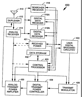
An exemplary transceiver 400 for use in a user terminal 126 to acquire
signals or channels in beams B1-B16 is illustrated in FIG. 4. Such
transceivers are known in the art and discussed in the patents referenced
above, such as U.S. Patent No. 5,109,390.
Transceiver 400 uses at least one antenna 410 for receiving
communication signals which are transferred to an analog receiver 414,
where they are downconverted, amplified, and digitized. A duplexer
element 412 is typically used to allow the same antenna to serve both
transmit and receive functions. However, some systems employ separate
antennas for operating at different transmit and receive frequency bands.
The digital communication signals output by analog receiver 414 are
transferred to at least one digital data receiver 416A and preferably at least
one digital searcher receiver 418. Additional digital data receivers 416B-
416N can be used to obtain desired levels of signal diversity or receive
multiple signals, depending on the acceptable level of unit complexity, as
CA 02266951 1999-03-26
WO 98/14026 PCT/US97/16976
would be apparent to one skilled in the relevant art. Additional searcher
receivers can also be used for implementing more complex signal
acquisition or searching techniques.
At least one user terminal control processor 420 is coupled to data
5 receivers 416A-416N and searcher receiver 418. Control processor 420
provides, among other functions, basic signal processing, timing, power and
handoff control or coordination, and selection of frequency used for signal
carriers. Another basic control function often performed by control
processor 420 is the selection or manipulation of PN code sequences or
10 orthogonal functions to be used for processing communication signal
waveforms. Control processor 420 signal processing can include a
determination of relative signal strength and computation of various
related signal parameters. Such computations of signal parameters, such as
timing and frequency may include the use of additional or separate
15 dedicated circuitry to provide increased efficiency or speed in
measurements
or improved allocation of control processing resources. For example, in
FIG. 4 a signal strength measuring element 421 is shown for using certain
information available in the analog receiver to determine the signal
strength or power for the overall received analog signal. Measuring
element 421 is also shown using outputs of, or data available from, the
digital data and searcher receivers for measuring the energy or power in
specific signals being received or demodulated.
Outputs for data receivers 416A-416N are coupled to remaining digital
baseband circuitry 422 within the user terminal. User digital
baseband circuitry 422 comprises processing and presentation elements used
to transfer information to and from a user terminal user. That is, signal or
data storage elements, such as transient or long term digital memory; input
and output devices such as display screens, speakers, keypad terminals, and
handsets; A/D elements, vocoders and other voice and analog signal
processing elements; etc., all form parts of the subscriber baseband circuitry
using elements well known in the art. If diversity signal processing is
employed, user digital baseband circuitry422 can comprise a diversity
combiner and decoder. Some of these elements may also operate under the
control of, or in communication with, control processor 420.
When voice or other data is prepared as an output message or
communications signal originating with the user terminal, user digital
baseband circuitry 422 is used to receive, store, process, and otherwise
prepare the desired data for transmission. User digital baseband circuitry 422
CA 02266951 2007-06-06
74769-175
16
provides this data to a transmit modulator 426 operating under the control
of control processor 420. The output of transmit modulator 426 is
transferred to a power controller 428 which provides output power control
to a transmit power amplifier 430 for final transmission of the output signal
from antenna 410 to a gateway or base station.
Information or data corresponding to one or more measured signal
parameters for received communication signals, or one or more shared
resource signals, can be sent to the gateway using a variety of techniques
known in the art. For example, the information can be transferred as a
separate information signal or be appended to other messages prepared by
user digital baseband circuitry 422. Alternatively, the information can be
inserted as predetermined control bits by transmit modulator 426 or
transmit power controller 428 under control of control processor 420, using
known "puncturing" or multiplexing techniques.
Data receivers 416A-N and searcher receiver 418 are configured with
signal correlation elements to demodulate and track specific signals.
Searcher receiver 418 is used to search for pilot signals, or other relatively
fixed pattern strong signals, while data receivers 416A-N are used to
demodulate other signals associated with detected pilot signals. For
purposes of determining signal strength, however, a data receiver 416 can be
assigned to track the pilot signal after acquisition to accurately determine
the
ratio of signal chip energies to signal noise. The pilot signal chip energies
are integrated over predetermined intervals, such as symbol periods, to
formulate pilot signal strength. Therefore, the outputs of these units can be
monitored to determine the energy in or frequency of the pilot signal or
other signals. These receivers also employ frequency tracking elements that
can be monitored to provide current frequency and timing information, to
control processor 420 for signals being demodulated.
An exemplary transmission and reception apparatus 500 for use in a
gateways 120 and 122 is illustrated in FIG. 5. Such apparatus is known in the
art and discussed in the patents referenced above. For example, additional
details on the operation of this type of apparatus are found in U. S. Patent
No. 5,103,459, issued April 7, 1992, entitled "System And Method For
Generating Signal Waveforms In A CDMA Cellular Telephone," assigned to
the same assignee as the present inventiork.
The portion of gateway 120, 122 illustrated in FIG. 5 has one or more
analog receivers 514 connected to an antenna 510 for receiving
CA 02266951 1999-03-26
WO 98/14026 PCT/US97/16976
17
communication signals which are then downconverted, amplified, and
digitized using various schemes well known in the art. Multiple
antennas 510 are used in some communication systems. Digitized signals
output by analog receiver 514 are provided as inputs to at least one digital
receiver module, indicated by dashed lines generally at 524.
Each digital receiver module 524 corresponds to signal processing
elements used to manage communications between one user terminal 124,
126 and a base station 112 or a gateway 120, 122, although certain variations
are known in the art. One analog receiver 514 can provide inputs for many
digital receiver modules 524, and a number of such modules are typically
used in gateways 120, 122 to accommodate all of the satellite beams and
possible diversity mode signals being handled at any given time. Each
digital receiver module 524 has one or more digital data receivers 516 and
preferably at least one digital searcher receiver 518. Searcher receiver 518
generally searches for appropriate diversity modes of signals other than pilot
signals. Where implemented in the communication system, multiple data
receivers 516A-516N are used for diversity signal reception.
The outputs of digital data receivers 516 are provided to subsequent
baseband processing elements 522 comprising apparatus well known in the
art and not illustrated in further detail here. Exemplary baseband apparatus
includes diversity combiners and decoders to combine multipath signals
into one output for each subscriber. Exemplary baseband apparatus also
includes interface circuits for providing output data, typically to a digital
switch or network. A variety of other known elements such as, but not
limited to, vocoders, data modems, and digital data switching and storage
components may form a part of baseband processing elements 522. These
elements operate to control or direct the transfer of data signals to one or
more transmit modules 534.
Signals to be transmitted to user terminals are each coupled to one or
more appropriate transmit modules 534. A typical gateway uses a number of
such transmit modules 534 to provide service to many user terminals 124,
126 at a time, and for several satellites and beams at a time. A base station
may also use a number of such modules, although base stations tend to
group transmit and receive functions more closely together in modem
structures. The number of transmission modules 534 used by gateway 120,
122 is determined by factors well known in the art, including system
complexity, number of satellites in view, subscriber capacity, degree of
diversity chosen, and the like.
CA 02266951 1999-03-26
WO 98/14026 PCT/US97/16976
18
Each transmit module 534 includes a transmit modulator 526 which
spread-spectrum modulates data for transmission. Transmit modulator 526
has an output coupled to a digital transmit power controller 528, which
controls the transmission power used for the outgoing digital signal. Digital
transmit power controller 528 applies a minimum level of power for
purposes of interference reduction and resource allocation, but applies
appropriate levels of power when needed to compensate for attenuation in
the transmission path and other path transfer characteristics. A PN
generator 532 is used by transmit modulator 526 in spreading the signals.
This code generation can also form a functional part of one or more control
processors or storage elements used in gateway 122, 124, or base station 112.
The output of transmit power controller 528 is transferred to a
summer 536 where it is summed with the outputs from other modulators
= or transmit power control circuits. Those outputs are signals for
transmission to other user terminals 124, 126 at the same frequency and
within the same beam as the output of transmit power controller 528. The
output of summer 536 is provided to an analog transmitter 538 for digital-to-
analog conversion, up-conversion to the appropriate RF carrier frequency,
further amplification and output to one or more antennas 540 for radiating
to user terminals 124,126. Antennas 510 and 540 may be the same antennas
depending on the complexity and configuration of the system.
At least one gateway control processor 520 is coupled to receiver
modules 524, transmit modules 534, and baseband circuitry 522; these units
may be physically separated from each other. Control processor 520 provides
command and control signals to effect functions such as, but not limited to,
signal processing, timing signal generation, power control, handoff control,
diversity combining, and system interfacing. In addition, control processor
520 assigns PN spreading codes, orthogonal code sequences, and specific
transmitters and receivers for use in subscriber communications.
Control processor 520 also controls the generation and power of pilot,
synchronization, and paging channel signals and their coupling to transmit
power controller 528. The pilot channel is simply a signal that is not
modulated by data, and may use a repetitive unchanging pattern or non-
varying frame structure type input (pattern) into transmit modulator 526.
That is, the orthogonal function, Walsh code, used to form the channel for
the pilot signal generally has a constant value, such as all l's or 0's, or a
well
known repetitive pattern, such as a structured pattern of interspersed l's and
0's. This effectively results in transmitting only the PN spreading codes
CA 02266951 1999-03-26
WO 98/14026 PCT/US97/16976
19
applied from PN generator 532. In addition, a pilot signal is non-power
controlled. That is, the pilot signal is transmitted at a preselected fixed
power level, which is not varied so that accurate measurements of signal
power are achieved by user terminals.
While control processor 520 can be coupled directly to the elements of
a module, such as transmit module 524 or receive module 534, each module
generally comprises a module-specific processor, such as transmit
processor 530 or receive processor 521, which controls the elements of that
module. Thus, in a preferred embodiment, control processor 520 is coupled
to transmit processor 530 and receive processor 521, as shown in FIG. S. In
this manner a single control processor 520 can control the operations of a
large number of modules and resources more efficiently. Transmit
processor 530 controls generation of, and signal power for, pilot,
synchronization, paging signals, and traffic channel signals, and their
respective coupling to power controller 528. Receiver processor 521 controls
searching, PN spreading codes for demodulation and monitoring received
power.
For certain operations, such as shared resource power control,
gateways 120 and 122 receive information such as received signal strength,
frequency measurements, or other received signal parameters from user
terminals in communication signals. This information can be derived from
the demodulated outputs of data receivers 516 by receive processors 521 or
receive power measuring elements 523. Alternatively, this information can
be detected as occurring at predefined locations in the signals being
monitored by control processor 520, or receive processors 521, and
transferred to control processor 520. Control processor 520 uses this
information (as described below) to control the timing and frequency of
signals being processed as well as the assignment of digital receivers for
user
signals.
Returning now to FIG. 2a, if a user terminal or subscriber unit
residing initially in a region serviced or covered by beam B10, traverses to a
region serviced by beam B15, because of either satellite or terminal motion,
any active or established communication link needs to be handed off
between the two beams to avoid disruption of communications. Actually,
in this situation, there are several handoffs that take place between any two
adjacent beams at a time, as several beams (B10, B2, B1/B7, B6) are traversed
in succession. This is shown in more detail in FIGS. 6a and 6b, where only a
CA 02266951 1999-03-26
WO 98/14026 PCT/US97/16976
few beams are shown adjacent to or along the perceived path for user ~
terminal 122.
In FIG. 6a, user terminal 122 travels along a straight path 610 from
point X to point Y. In FIG. 6b, a variable path 620 followed by user terminal
5 122 is more irregular, moving from point X to point Y, traversing an
additional beam B16. The path will depend on a variety of known factors
such as speed and direction of movement of the user terminal along the
surface of the Earth relative to the satellite, if moving, as well as the
orbit of
the satellite. This is a perceived path or projected change of location for
the
10 user terminal relative to the beam pattern. If the user terminal is at rest
on
the Earth, a generally straight path results as the beams sweep by the user
terminal, except as altered by localized satellite movements. For example, it
is well known that satellite orientation may be changed from time to time,
such as by adjusting yaw, to account for seasonal changes in Earth and Sun
15 positions or alignments. User terminal motion increases or decreases the
rate of change along the path for movement parallel to the satellite orbit
direction, and creates irregularities when directed at angles to the orbital
plane. Regardless of the shape of the path, the general principles of the
invention and its application are the same.
20 As shown in FIG. 6a, user terminal 122 crosses between two beams,
initially B10 and B2. In the vicinity of the beam crossover, a transition
region is entered in which two adjacent beams are present in the location of
the user terminal. That is, in this region, a user terminal can detect the
presence of the pilot signals for both beams. In a traditional cellular
handoff
scheme, the user terminal uses a searcher receiver to acquire the new pilot
signal as it is encountered and a digital receiver is assigned to demodulate
signals associated with that pilot, so that a 'soft handoff' type
communication link can be established. After, the new link is established,
the user terminal waits until it moves out of the beam coverage for the
previous pilot signal (B10) and then drops the link related to that pilot
signal.
Unfortunately, as discussed above, unlike typical multipath reception,
there is no benefit in receiving signals using two of these beams on the
forward link. In typical diversity signal reception, the signals to be
combined
are received over markedly different signal paths, either from different
satellites or reflections from surfaces, and so forth. In that situation, the
propagation paths are different enough in terms of time, attenuation, and
other path effects, to allow gain from combining. However, for single
CA 02266951 1999-03-26
WO 98/14026 PCT/US97/16976
21
satellite transfer of multiple beams of signals, the signals are transferred
over virtually identical signal paths and the transit time is very nearly the
same. Therefore, from a timing and phase point of view, little is to be
gained, for diversity combining these signals.
In fact, diversity reception of two beams for forward link
communication between a satellite and a user terminal can degrade system
performance in several ways. This process involves excessive use of
available resources. First, power is required in each beam for the satellite
to
transfer signals to the user terminal. Second, for systems utilizing
orthogonal codes, at least one code is used in each beam for the user
terminal. However, where there is no gain in signal processing, this
represents lost power for the satellite and loss of use of a code. This
translates to a decrease in system capacity, and unnecessary potential signal
interference.
A corresponding illustration is provided in FIG. 6c for cell 220. Here,
a variable or irregular path 630 is followed by user terminal 122 in moving
from point X to point Y, traversing sectors S3, S4, S5, S6, and S1. The path
depends on a variety of known factors such as speed and direction of
movement of the user terminal, as well as any changes in sector boundaries.
In FIG. 6c, the overlapping boundaries are again shown using solid and
dashed lines. Regardless of the shape of the pa;h, the general principles of
the invention and its application are the same. As in the case of multiple
satellite beams, there is generally little if any benefit in receiving signals
using two of these sectors on the forward link, except in certain
circumstances.
The present invention takes advantage of some of the properties of
sectors, satellite beams, and communication links and their control, to
improve the handoff scheme for beam-to-beam or sector-to-sector
transitions. The present invention decreases the power and code resources
required for each user terminal undergoing such transitions, while
maintaining 'soft' communication links. A flow chart representing of the
steps used to implement handoff processing according to one embodiment
of the present invention is illustrated in FIG. 7.
It is readily understood that due to the shape of the beams, there is a
power or energy distribution across the beams that places lower power near a
beam edge. Generally, this means that one or the other of the two beam
signals is largest. Therefore, the transition from one beam to the next
results
in a gradual or rapid (depending on transition speed) build up in received
CA 02266951 1999-03-26
WO 98/14026 PCT/US97/16976
22
power for one beam and a corresponding decrease in power from the other.
That is, an increase or decrease in signal strength for received pilot signals
is
detected during a transition between the two adjacent beams. Where two or
more beams intersect or overlap completely, the power of the beams may
also be balanced substantially the same. The same effect is observed for
adjacent sectors in a cell.
As seen in a step 710 of FIG. 7, a user terminal detects and acquires a
pilot signal at some point in time, and uses this signal to establish a
forward
communication link. This could occur when the user terminal first
commences communication, such as when starting at point X in beam B10,
in FIG. 6a, or sector S4 in FIG. 6c. If several pilot signals are detected by
a
user terminal, generally the strongest signal is chosen for further
processing.
However, those skilled in the art will readily understand that other basis for
selecting a pilot signal can be used as desired within the communication
system, when first establishing a communication link. For, example some
pilot signals could represent or originate from gateways which a particular
user terminal is not allowed to communicate with for various technical or
procedural reasons.
As discussed above, the use of pilot signals represents one preferred
mode of operation for the invention, and other strong shared resource
signals such as paging signals may also be used as desired.
The first acquired pilot signal is used, in a step 712, as a timing and
phase reference to acquire and demodulate forward link communication
signals associated with that pilot, or the base station or gateway
transmitting
that pilot. However, as the user terminal or the satellite moves, or as cell
or
beam boundaries are adjusted, at least one new pilot signal is detected in a
step 714, as the user terminal approaches a beam or sector boundary or edge.
A user terminal searcher receiver generally acquires this new pilot signal
(step 714) and its relative signal strength is determined in a step 716, as
compared to that of the previously selected pilot signal (step 710). The
strength of the new pilot will either grow larger and larger as the user
terminal crosses further into the new beam, or it will decrease as the path
changes to enter another beam or move farther interior of the original
beam.
As long as the signal strength of a newly detected pilot signal is less
than that of the previous or already in use pilot signal at this point, the
new
pilot is not used to establish a new communication link or to set up a
channel in the new beam. However, the new pilot signal strength can be
CA 02266951 1999-03-26
WO 98/14026 PCT/US97/16976
23
compared to a predetermined threshold power level in an optional step 720.
When the new pilot signal reaches this power level, which is still less than
that of the previously chosen or in use pilot, the user terminal informs the
communication system, or a particular gateway or base station in a step 722.
The user terminal can simply report the signal strength measurement or
that it exceeds the threshold, and allow the gateway to decide when a beam
or sector transition is occurring. Alternatively, the user terminal makes a
determination and reports that a transition appears to be approaching and
requests a new channel, depending on user terminal or system complexity.
There is no requirement for reserving a forward link channel on the
beam although this may be preferred where system capacity is substantially
occupied and a channel will be needed to prevent call termination. This
type of action can be used for 'priority' users where desired to maintain
links. Channel reservation generally means that an orthogonal code is
reserved for use by that user terminal, or at least assigned a priority for
its
use.
This first threshold power level is generally established at a few dB
less than the strength of the current in use pilot, to minimize signal
processing for brief excursions into the edge of a new beam coverage region.
Those skilled in the art will readily understand how to select a threshold
value based on the desired amount of beam transition to ignore, and
availability of resources in the communication system. This threshold can
be a static value or dynamically changeable. The value can be updated as
part of the initial system communication with the user terminal, or on a
periodic basis, and stored in a memory element for future use by a user
terminal controller.
At some later time, the user terminal determines that the strength of
the new pilot signal is at least equal to that of the previous pilot signal,
in a
step 730. At this point, the user terminal transmits this information or a
channel request to the gateway or base station so that a new forward link
communications channel is set up for the user terminal. Alternatively, an
already reserved channel (from step 722) is now used. This request may be
processed by or through the central switching station or a ground operations
control type facility as previously discussed above. In addition, the setup of
forward link channels need not occur at an exact equality in signal strength,
and a lower "threshold" type value for the new pilot signal strength can be
chosen as desired. Again, depending on allocation of system resources.
CA 02266951 1999-03-26
WO 98/14026 PCT/US97/16976
24
Those skilled in the art of designing communication systems are familiar
with the criteria used for selecting this threshold level.
At this point, the new channel in the new beam is selected for use in a
step 732, and the user terminal communicates both over a channel
associated with the older pilot and beam, and over a channel associated with
the new pilot and beam. This is similar to more conventional soft handoff
signal processing on the forward link. The communication system, through
the gateway or base station, is informed of the use of these two
communication links or paths by the user terminal.
However, as soon as the gateway receives confirmation, in a step 734,
from the user terminal that the forward traffic signal is being received
satisfactorily from the new beam (channel), the previous beam (channel)
signal is taken down, inactivated or dropped, in a step 736. That is, the
first
beam is no longer used for communication on the forward link with the
user terminal. However, in some embodiments the previous forward link
channel may still be reserved for use for some period of time, in case the
user terminal needs to switch back. This process results in what can be
termed a "quick", "fast", or "high-speed" soft handoff.
The return link signal in any beam is held as long as it proves useful
in processing signals. When the return link reception in any beam or sector
is too weak, attenuated, or significantly blocked to provide a useful signal
path, it is dropped by the gateway or base station. The return and forward
links may be established through separate beam or sector configurations that
differ significantly in coverage area or shape. Therefore, so the use of new
and termination of old channels or beams for these two link directions occur
independently of each other and may differ substantially.
Generally, confirmation step 734 involves determining certain well
known attributes or criteria of the communication signals being received.
For example, determining if the signals have sufficient energy, low enough
error rates, and so forth, to support a desired level of communications. This
determination can occur in a very short time span. As an example,
confirmation can be accomplished using known signal parameter
examination techniques in the user terminal, or by using preselected test
data or patterns in signals transmitted to the user terminal which are
retransmitted to the central station for receipt and analysis.
In typical satellite communication systems and under normal
conditions, confirmation occurs after a few frames of data have been
transferred to the user terminal. With a typical data frame in such systems
CA 02266951 1999-03-26
WO 98/14026 PCT/US97/16976
being on the order of 20 ms in length, the total time two beams are in use is
on the order of 20-80 ms for measuring signal quality, plus some additional
time to account for signal delay through the satellite (around 10 ms or
more). Little or no delay is generally involved for sectored cellular systems.
5 There are several approaches to determining and utilizing the pilot
signal strength measurements. The user terminal can try to determine the
strength of each pilot and compare them by either measuring each separately
in a "direct" or absolute power sense, or "indirectly" by trying to measure a
relative difference upon receipt.
10 For example, as previously shown in FIG. 4, the amount of energy in
a pilot signal can be determined from information or measurements
available in searcher 418 and receivers 416A-N, using measuring element
421 and control processor 420. The same measurement can be taken for two
beams, sectors, or pilots and stored in data storage element 432 between
15 comparison operations, as desired. Searcher receiver 418, is generally time
shared, or switched between pilots signals, or additional receivers are used
(416 or 418) for the strength measurements._
Unfortunately, various path, frequency, and transmission factors
which may be known by the gateway, or base station, can effect the incident
20 pilot power from beam-to-beam in a manner that makes measuring
individual pilot signals inaccurate. In addition, computing or otherwise
determining relative signal strengths, and monitoring changes or trends in
pilot signal power can consume more resources than are sometimes
desirable to provide in a user terminal.
25 One solution to these problems is to have the gateway or base station
determine the relative and absolute pilot signal strengths from information
provided by the user terminals. This is a preferred approach because the
decision can be handled very efficiently by the gateway, or base station,
communicating with the user terminal. In this approach, the user terminal
simply reports the level of signal strength being received or a relative
value,
and changes being experienced. The user terminal can also report when
signals are above a certain predetermined threshold. This process is shown
in FIG. 8, where the first threshold test has been omitted.
In FIG. 8, as before, a user terminal measures the pilot signal strength
in a step 810. This is generally accomplished by integrating received pilot
signal chip energies over a preselected time interval, such as a symbol
period, in a data receiver. This information is generally already available as
part of various known signal demodulation and tracking schemes used by
CA 02266951 1999-03-26
WO 98/14026 PCT/[1S97/16976
26
user terminals. The information is then temporarily stored, as desired, and
either embedded in or appended to other communication signals or
transferred as a separate pilot information signal to the signal source,
either
a gateway or base station, in a step 812.
Gateways and base stations receive such signals containing signal
strength information in a step 814, and extract the data, using techniques
known in the art. The information is either automatically or easily
associated with corresponding user terminals and beams. The gateway then
uses this information, along with known transmission power levels and
relative differences for pilot signals being transmitted in a step 830 to
determine the relationships between pilot signals being detected or received
by the user terminal. That is, to see if the new pilot signal strength exceeds
the old. This allows the gateway or base station to determine relative power
levels and when beam or sector boundaries are being traversed. This
information can then be transmitted back to the user terminal as part of
various known signals in a step 831.
The gateway establishes a new channel for the user terminal to use in
a step 832, having determined when one is desired, in accordance with
known capacity limitations, or various channel assignment procedures and
schemes. The user terminal will then confirm proper operation of the new
channel as before in a step 834, or the gateway can use certain known
feedback mechanisms 'or predefined transmit-and-receive test signals to
confirm channel operation, before dropping the old channel in a step 836.
Depending upon the level of signal synchronization established in setting
up the new channel, step 834 can be optional, as discussed below. This then
is a "passive" handoff technique.
The gateway or base station can receive periodic reports of pilot signal
strength from user terminals, either in response to transmitted messages
requesting such information, or at preselected reporting intervals. The
gateway can update and maintain signal strength information to predict
when user terminals approach various coverage area boundaries.
An advantage of this approach is that any computation resources are
limited in terms of apparatus and processing time consumed by a user
terminal. Resources can be more easily and cost effectively implemented in
base stations and gateways. Another advantage of this approach is that it
allows an alternative embodiment that can be referred to as a "firm" or
"synchronized" soft handoff technique.
CA 02266951 1999-03-26
WO 98/14026 PCTIUS97/16976
27
Because the gateway or base station is maintaining data on pilot signal
strength from each user terminal, transitions across beam and sector
boundaries can be detected very accurately and quickly. Therefore, the
gateway can be fully prepared to communicate with a user terminal on
multiple beams or sectors (adjacent) to allow rapid changing of channels or
channel assignments for a user terminal. The multiple forward link
communication paths are fully controlled by the gateway, in combination
with central control centers, and all synchronization, timing, and code use
issues can be completely resolved in advance of when a handoff to a new
beam or sector is desired. Therefore, the gateway can switch the user
terminal communications link or path and drop the use of the traffic signal
associated with the first pilot and associated signals or beam virtually
instantly.
Another problem may occur as a result of "roll-off" near beam or cell
edges or boundaries. As with any signal, but more importantly here the
pilot signal, there is an increasingly sharp drop off near the outer edges of
a
beam. This is a natural result of the power versus distance relationship for
signals, as well as beam forming systems. In satellite systems, the impact is
exaggerated in outer beams in the satellite spot. That is, due to the larger
displacement of these beams from a central area, the rate of decrease in
signal amplitude at outer edges of the beams may be much more noticeable
than for inner beams.
Roll-off is also increased or exaggerated by certain well known Power
Field Density (PFD) requirements or restrictions placed on satellite signals.
In order to reduce certain types of signal interference, a limitation is
placed
on the power density of signals projected from satellites. This limitation has
its greatest impact near the far edges of satellite spots, and some form of
compensation is generally implemented in the beams near the outer edges.
This compensation further reduces incident power in these areas in order to
stay within dictated guidelines. Unfortunately, such adjustments greatly
increase the rate of power roll-off.
Unfortunately, reduced power in pilot signals also reduces that ability
to use them to demodulate paging, traffic, and other signals. Since there is a
desire to maintain or increase system capacity across the total service area
of
the beams, one technique to counter signal drop-off is to boost the pilot
signal power as it is directed to outer beams or beam boundaries. This can be
referred to as a "pilot adjust" technique, and provides a corresponding
CA 02266951 1999-03-26
WO 98/14026 PCTIUS97/16976
28
improvement in signal reception, tracking, demodulation and so forth
increasing the number of system users near boundaries.
However, the use of pilot boosting or level adjustments of any type,
including decreasing levels where desired, masks the true beam and sector
boundaries. That is, what is normally thought of as "true" beam boundaries
will be virtually changed or shifted for a system that uses pilot signal
strength to account for or detect such boundaries. If the pilot signal level
is
boosted to have an artificially compensated or stronger level near a
particular boundary, the detection mechanism incorrectly determines that a
boundary is either closer or farther away than it should, based on typical
signal roll-off, depending on direction of travel and pilot level controls in
adjacent beams.
Where "pilot adjustment" is utilized, the handoff method of the
present invention can employ a "pilot-adjust" command or designation
technique to allow the user terminal to more accurately and correctly
determine the relative position of beam and sector boundaries. That is, the
use of "pilot adjustment" is denoted as part a communication signal sent to
the user terminal for each corresponding beam. This can be done by again
embedding or appending a command as part of a paging or traffic signal, or
at certain locations within pilot signals and so forth. This information
allows a user terminal to compensate to some degree for the pilot boost
being used. This approach can be made more useful by also providing some
relative indication of the amount of boost used, which can occur in
predefined steps if desired.
In the alternative, where the gateway or base station is computing
various pilot strength relationships, the pilot boost information is already
available within the gateway or base station for each beam. This process can
also allow some adjustment to the pilot adjustment itself, if a large number
of user terminals are making transitions and there are any problems.
Use of such "pilot-adjust" commands and processing is shown in
FIG. 9, where a pilot signal level adjustment process 910 (dashed outline) is
shown occurring between steps 716 and 730, normally used to measure and
compare pilot signal levels. Process 910 can occur before or after first
threshold test step 720 in FIG. 7, or strength determination step 816 shown in
FIG. 8, as well.
In process 910, a determination is made in a step 912 as to whether or
not the pilot has been adjusted. The step 912 determination uses
information available to either a user terminal, or gateway and base station.
CA 02266951 1999-03-26
WO 98/14026 PCTIUS97/16976
29
Where there is no pilot adjust, signal processing after step 912 occurs as
before, without benefit of any correcting adjustment. Where no
information is available regarding pilot adjustment, the answer obtained in
step 912 also indicates no adjustment. Where the pilot is known to have
been adjusted, the level of the pilot is re-adjusted or counter-adjusted in a
step 914 to make a more accurate comparison possible in steps 730 and 830.
The amount of adjustment imparted to the pilot may be specified in
advance or use dynamically varying information.
The above embodiments of the new handoff process result in only
one of the beams being used for forward link signals, with corresponding
channel codes and satellite energy, a majority of the time. Two beams are
used for only a very brief time, while maintaining the advantage of a soft
handoff approach to prevent loss of communications. The operation of the
present invention leads to what can be termed as either a "quick" soft
handoff technique or a "firm" handoff technique.
While the above embodiments represent improvements over current
handoff signal processing techniques, there is one occasion when some
system resources may still be wasted. This situation occurs when a user
terminal path is directed along a common chord for two neighboring beams.
That is, where the user terminal is traversing a path that places the user
terminal substantially equidistant from the boundaries of two (or more)
neighboring beams being traversed. This also occurs where a user terminal
is substantially equidistant from the boundaries of two sectors. A similar
problem also occurs when a course followed by the user terminal
repetitively crosses adjacent boundaries on a relatively short time scale.
These processes are illustrated in FIGS. 6a, 6b, and 6c. In FIG. 6a, a
portion 612 of the user terminal path 610 is equally balanced between the
adjacent beam boundaries. In FIGS. 6b and 6c, portion 622 of path 620, and
portions 632 of path 630 are shown wandering back and forth between
adjacent beam and sector boundaries.
In these situations, the user terminal may never have a clearly
stronger pilot signal, or the second pilot strength does not consistently
exceed the first for more than brief periods. In both of these instances, the
user terminal may switch back and forth between two pilots and beams or
sectors, as they just meet the threshold criteria, but only for brief periods
of
time, on the order a few seconds. This causes the user terminal and
gateways or central controllers to consume precious processing time in
switching channels and beams, and redirecting communication signals. In
_. ..___~:~w...~.~..~... ___.
CA 02266951 1999-03-26
WO 98/14026 PCT/US97/16976
addition, frequent shifting between beams or sectors, reduces the period of
single beam coverage, effectively producing the current problematic soft
handoff scheme.
To minimize the inefficient use of system resources, and prevent a
5 user terminal near a transition point or within a transition region for
extended periods of time from changing beams frequently, a form of
hysteresis can be built into the pilot signal processing. The use of
hysteresis
in illustrated in FIG. 9, where a hysteresis process 920 has been inserted
between pilot level determination step 730 and beam use step 732. As will be
10 readily apparent to those skilled in the art, process 920 can also occur
after
comparison determination step 730 in FIG. 7, or determination step 830
shown in FIG. 8.
Hysteresis process 920 can be accomplished for example by requiring
in a step 912 that the user terminal use a current pilot signal, or associated
15 beam or sector channels, for a minimum length of time, subject to certain
preselected minimum signal strength or potential link loss exceptions. As
long as the minimum time has passed, the terminal is allowed to switch
beams and pilots and proceed as before. However, if the time test fails, the
new beam cannot be selected at this point, in spite of passing other threshold
20 tests.
In some embodiments, each pilot signal being used can be identified
and its identification or relevant characteristics recorded by the user
terminal controller in some memory location. For example, a specific
spreading code being used, or some other known beam or pilot specific
25 identification feature, such as predefined beam "IDs", can be detected.
This
information can be used by a user terminal, such as through a searcher
receiver, to determine if the same pilot is being detected again within a
short
period of time. The user terminal can use known internal clocks or timing
circuits along with memory elements to record the length of time a
30 particular pilot or corresponding traffic signal has been in use.
Therefore, steps can be taken to minimize the frequency with which
or minimum time interval over which a beam or sector can be re-selected.
The period of time for which a beam or sector must be used before another
can be selected, or minimum time before a pilot selection can be "repeated"
can be determined in advance by communication system designers from the
overall amount of system resources expected to be available, and other
known criteria. The user terminal is provided this information when setup
CA 02266951 1999-03-26
WO 98/14026 PCTIUS97/16976
31
to operate within the system, but this information may be updated as part of
various system overhead information in transmitted signals.
An alternative or adjunct to using a time requirement, as in step 912,
is to employ a minimum change in signal strength requirement in a step
914. In this mode of operation, the current pilot signal is required to
decrease below a pre-selected second threshold before a new pilot signal is
selected. That is, the pilot signal strength must decrease below some
percentage of the value used to select that pilot before another pilot is used
as the basis for switching to a new beam or sector service area. This
requirement forces the user terminal to stay with a viable communication
link longer and not switch beams until the user terminal is clearly moving
deeper into a new beam, and not simply skirting the edge of a new beam in
some more transient manner.
Using the above techniques, a user terminal can efficiently select pilot
signals and move between beams being projected by a single satellite,
without losing communications, yet using a minimum amount of system
resources. Likewise, a user terminal can effectively select pilot signals
while
moving between adjacent sectors in a cell. Transmitted power, which is one
of two primary limitations on system user capacity, is minimized, for a
given signal to noise ratio, on the ground for satellites, if all of the power
is
diverted into beams with larger signal strength.
The previous description of the preferred embodiments is provided to
enable any person skilled in the art to make or use the present invention.
The various modifications to these embodiments will be readily apparent to
those skilled in the art, and the generic principles defined herein may be
applied to other embodiments without the use of the inventive faculty.
Thus, the present invention is not intended to be limited to the
embodiments shown herein but is to be accorded the widest scope consistent
with the principles and novel features disclosed herein.
What I claim is: