Note: Descriptions are shown in the official language in which they were submitted.
CA 02267102 1999-03-26
WO 99/06739 PCT/US98/15626
1
Belt Drive Differential
Background of the Invention
The invention relates to planetary gear transmissions and components,
but more particularly, the invention relates to a belt drive differential
where a
planet pinion engages a flexible belt.
In a belt drive differential, planet pinions in the form of pulleys are
rotatably mounted to a carrier and orbited in a circular path about a carrier
axis.
Output pulleys arranged substantially coaxial with the carrier axis transmit
power
to shafting.
In a belt drive differential, two or more planet pulleys are rotatably
mounted to a carrier and orbited in a circular path with the carrier about a
carrier
axis. Two output pulleys are arranged coaxial with the carrier axis and a belt
bent in a circuitous path is entrained around and engages the planet pulleys
and
output pulleys which are in different planes. Such a drive with multi-plane
pulleys is commonly known as a mule pulley drive.
In the belt differential disclosed in U.S. Patent No. 3,543,608 to Meihak,
coaxial planet V-pulleys are used in conjunction with a V-belt and output V-
pulleys individually fixed to and near ends of separate shafts that are
coaxial
with the carrier axis. Ends of the two shafts are commonly journaled to the
carrier and require additional journaling with thrust capability to prevent
axial
separation of the commonly journaled shaft ends and the fixed output V-
pulleys.
The position of the planet V-pulleys require periodic adjustments for "belt
take
up" by means of threaded fasteners to adjust belt tension and to compensate
for
belt wear. Summarily, the V-belt drive has limited power capability, requires
CA 02267102 1999-03-26
WO 99/x6739 PCT/US98/15626
2
intermittent belt take-up adjustments which has the effect of changing belt
drive
length to minimize V-belt slippage; and two shafts are required, one fixed to
each of the two output pulleys.
In the belt differential disclosed in U.S. Patent No. 5,445,572 to Parker,
both non-coaxial frustoconcial and cylindrical planet pulleys are used in
conjunction with a toothed synchronous belt and output sprockets individually
fixed near ends of separate tubular gear shafts that are coaxial with the
carrier
axis and are journaled over a central or third coaxial shaft. The two tubular
shafts require additional journaling with thrust capacity to prevent
separation of
the tubular shaft ends with fixed output sprockets. The position of the planet
frustoconical pulleys and cylindrical pulleys require belt take-up adjustment
for
belt drive length to tension the belt to impede it from ratcheting on the
output
sprockets. A second set of frustoconical guide pulleys are also required
juxtaposed the belt and opposite planet pulleys to help guide the belt and
impede belt ratcheting. Summarily, the synchronous belt drive requires
adjustment of the belt drive length to minimize belt ratcheting on the output
sprockets; frustoconical rollers are required to impede belt movement that can
cause belt ratcheting; and three shafts are required, one fixed to each of the
tubular gear shafts and, a central shaft.
There are several major problems with the aforementioned belt drives. A
major problem is that there is not a fixed or constant belt drive length. The
position of the planet pulleys must be re-adjusted for belt take-up to obtain
or
change to a belt drive length where V-belt slipping or synchronous belt
ratcheting is impeded.
Another problem with the prior art belt drive differentials is associated with
the use of multiple output shafts. The output pulleys or sprockets are each
connected to separate shafts. Special journaling with thrust capability is
required to keep the output sprockets and pulleys in a position that does not
CA 02267102 1999-03-26
WO 99/Q6739 PCT/US98/15626
3
impact belt drive length. The use of a third or central shaft introduces a
problem
of lubrication and fretting corrosion with the journaled tubular shafts.
A particular problem with the Parker '572 belt drive differential is that it
uses planet pulleys as idlers that engage the tips of belt teeth to adjust
belt drive
length and define a curved surface about which belt bending is forced. The
pulleys press against the tips of the belt teeth allowing the belt tensile
member
(i.e., cord) to bend at very small bending radii in areas between belt teeth
which
causes crimping of the belt's tensile member that is deleterious to belt life.
The
smaller the radius of the pulley, the shorter the belt life. The use of
frustoconical
pulleys is particularly deleterious to a cord tensile member because the belt
must
bend over various radii across its width as it presses against the
frustoconical
pulley.
A belt drive length is associated with the length of the belt's tensile
member because belt bending takes place at the tensile member.
Consequently, bending of a synchronous belt and its belt drive length cannot
be
precisely controlled by a small diameter planet pulleys that press against
tips of
belt teeth.
Summary/ of the Invention
In accordance with the invention, a belt drive differential is provided that
is particularly useful in light duty applications such as golf carts, small
tractors,
and lawnmowers where it is desirable or necessary for at least two drive
wheels
to operate at different rotational speeds. The belt drive differential has at
least
one output shaft, two planet sprockets rotatably mounted to a carrier to orbit
in a
circular path about a carrier axis that is coaxial with the output shaft, and
first
and second output sprockets coaxial with the output shaft. The arrangement of
the planet sprockets and the output sprockets define a mule pulley drive
having
a fixed length that does not need to be intermittently adjusted for belt take-
up.
CA 02267102 2006-02-23
25145-290
4
In a preferred arrangement, the first output
sprocket is attached to the output shaft and the second
output sprocket is journaled to the output shaft. A first
drive pulley is attached to the output shaft and a second
drive pulley is journaled to the output shaft and attached
to the second output pulley to rotate therewith. A toothed
belt is entrained around the planet sprockets and output
sprockets to complete the drive. The advantage of this
arrangement is that a single output shaft is used which has
the advantage of help maintaining a fixed belt drive length
and the shaft helps to provide excellent alignment for the
belt of the mule pulley drive.
The invention may be summarized according to one
aspect as a belt drive differential of the type with at
least two planet pulleys rotatably mounted to a carrier to
orbit in a circular path with the carrier about a carrier
axis at least two output pulleys arranged coaxial with the
carrier axis where at least one of the pulleys is attached
to a coaxial output shaft and a belt entrained around the
pulleys, wherein the improvement. comprises: the two planet
pulleys being in the form of toothed planet sprockets that
are spaced-apart with planet axes that are spaced from the
carrier axis; the two output pulleys being in the form of
toothed output sprockets and wherein the planet sprockets in
conjunction with the output sprockets define a mule drive
having a fixed belt drive length; and the belt being in the
form of a synchronous belt with belt teeth that engage the
toothed planet sprockets and toothed output sprockets and
whenever the belt is substantially tangent to each of the
sprockets across its width.
CA 02267102 2006-02-23
25145-290
4a
According to another aspect the invention provides
a belt drive differential comprising an output shaft; a
carrier journaled to the output shaft; a first output
sprocket attached to the output shaft juxtaposed an axially
facing side of the carrier; a second output sprocket
journaled to the output shaft juxtaposed an opposite axially
facing side of the carrier; first and second spaced apart,
planet sprockets coaxial to a planet axis and journaled to
at least one shaft attached to the carrier and wherein the
planet axis is spaced from and substantially perpendicular
to the output shaft; a toothed belt entrained around the
first and second output sprockets and first and second
planet sprockets; a first drive sprocket attached to the
output shaft; and a second drive sprocket journaled to the
output shaft and attached to the second output sprocket.
These and other advantages of the invention will
be apparent after reviewing the drawings and description
thereof wherein:
Figure 1 is an isometric view of the belt drive
differential of the invention and further includes
schematics of portions of optional belt drives; and
Figure 2 is a cross sectional view taken along the
line 2-2 of Figure 1.
Description of Preferred Embodiment
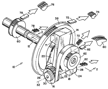
Referring to Figures 1 and 2, a belt drive
differential 10 of the invention has an output shaft 12, a
carrier 14, two planet sprockets 16, 18, two output
sprockets 20, 22, and a toothed belt 24 entrained around the
sprockets.
CA 02267102 2006-02-23
25145-290
4b
The planet sprockets, which may include flanges
26, 28, to help guide the belt, are rotatably mounted to the
carrier on at least one shaft 30.having a planet axis 32.
Optionally but preferably, the planet sprockets 16, 18, are
coaxial with each other along the planet axis. With such a
coaxial arrangement, the belt is
CA 02267102 1999-03-26
WO 99/06739 PCT/US98/15626
substantially tangent to all sprockets across its width. However, the planet
sprockets may be arranged with their axis at an angle to each other provided
that the belt is substantially tangent to the sprockets across ifs width.
5 The carrier 14, and output shaft 12, have substantially the same,
concentric axis 34. The carrier 14 is journaled to the output shaft such as by
means of a plastic bushing 36. The carrier is thus free to rotate about the
shaft
to orbit the planet sprockets in a circular path about the carrier axis 34.
The carrier 14 is rotated about its axis 34 by means of an input wheel
such as an input sprocket 38 attached to the carrier such as by means of
threaded fasteners 40. The input sprocket is journaled to the output shaft
such
as by a plastic bushing 42. Thus, the carrier and attached input sprocket are
free to rotate together around the output shaft.
One of the output sprockets 20 is attached to the output shaft 12 such as
by means of a key 43 so that the output sprocket rotates with the output
shaft.
The output sprocket 20 is located juxtaposed a axially facing side 44 of the
carrier. The other or second output sprocket 22 is located juxtaposed and
oppositely facing side 46 of the carrier and is journaled to the output shaft
12
such as by means of a plastic bushing 48. Thus, the output sprocket 22 is free
to rotate about the output shaft 12.
The pivot axis 32 is spaced from the carrier axis and is substantially
perpendicular to the carrier axis in a radial plane 50. Optionally, but
preferably,
the carrier includes an adjustment mechanism 52 for radially moving the planet
axis 32 in the radial plane for the purpose of establishing a fixed drive
length for
the belt when it is appropriately tensioned.
The adjustment mechanism 52 includes a movable carriage 54 to which
the shafts) 30 are attached. The carriage is adjusted by rotating threaded
*rB
CA 02267102 1999-03-26
WO 99/Q6739 PCT/US98/15626
6
fastener 56 which translates the pivot axis radialiy inward or radially
outward with
the carriage. The carriage is locked into its adjusted position by means of a
threaded fastener 58.
A new synchronous or toothed belt needs to be pretensioned to
compensate for a tension decay that occurs when a belt is operated for the
first
time under a load. The adjustment mechanism 52 facilitates the tensioning of
the belt and establishing a fixed belt drive length that needs or requires
little or
no additional adjustment over the operating life of the belt.
A first drive sprocket 60 is attached to the output shaft to rotate therewith.
A second drive sprocket 62 is journaled to the output shaft such as by means
of
a plastic bushing 64, and it is attached to a side of the output sprocket 22
such
as by means of threaded fasteners 66. The second drive sprocket 62 along with
output sprocket 22 is free to move axially along the output shaft a
predetermined
amount between stop 68 as a collar or washer placed over the output shaft, and
a flanged stop such as a threaded fastener 70. The freedom of movement
facilitates an automatic alignment of the belt and sprocket under load. The
mass
of the carrier may be increased 71 radially opposite the planet sprockets 16,
18,
to provide a dynamic counterbalance to the radially off set planet sprockets
to
inhibit vibration.
In use, the belt drive differential may be powered through the input
sprocket by means of a synchronous belt 72 that engages and is entrained a
powered driver sprocket 74 and the input sprocket 38. Any means (not shown)
such as an electric motor or internal combustion engine may be used to power
the drive sprocket 74. The carrier 14 is attached to and rotates with and
turns
the same number of revolutions as the input sprocket 38. The planet sprockets
16, 18, pull on the belt 24 to rotate the output sprockets 20, 22 in the same
direction of rotation as the carrier. The output sprockets 20, 22 turn with
the
same number of revolutions as the carrier provided that there is no
differential
CA 02267102 1999-03-26
WO 99/06739 PCT/US98/15626
7
speed requirement between the first drive sprocket 60 and second drive
sprocket 62. The first drive sprocket 60 may be used to transmit power to a
final
drive sprocket 76 by means of an synchronous or toothed power transmission
belt 78. Similarly, the second drive sprocket 62 may be used to power a second
final drive sprocket 80 by means of an entrained synchronous belt 82.
The mule drive is activated when required and it permits the first drive
sprocket and second drive sprocket to be operated at different rotational
speeds.
To explain, assume the input sprocket 38 is held station~~~~ and the output
shaft
12 is rotated one revolution clockwise. The output sprocket 20 being attached
to
the output shaft, also rotates one revolution in the clockwise direction,
Rotation
of the output sprocket 20 circulates the toothed belt 24 and the other output
sprocket 22 in the opposite direction one revolution or counterclockwise as
the
sprocket is journaled to the output shaft. Simultaneously, the second drive
sprocket 62 turns one revolution counter clockwise because it is directly
attached to output sprocket 22.
CA 02267102 1999-03-26
WO 99/06739 PCT/US98/15626
8
By way of example, a belt drive differential with other belt drives as
illustrated in Figure 1 was constructed and satisfactorily operated. The
configuration was as follows:
power drive sprocket 74 25 teeth, 14 mm
pitch
belt 72 124 teeth, 14 mm
pitch
input sprocket 80 teeth, 14 mm
pitch
planet sprockets 16, 18 32 teeth, 5 mm
pitch
output sprockets 20, 22 61 teeth, 5 mm
pitch
belt 24 148 teeth, 5 mm
pitch
drive sprockets 60,62 25 teeth, 14 mm
pitch
belts 78, 72 148 teeth, 14 mm
pitch
final drive sprockets 76, 80 80 teeth, 14 mm
pitch
power to sprocket 74 2 hp, 0 to 4200
rpm
The foregoing detailed description is made for purpose of illustration and
is not intended to limit the scope of the appended claims.