Note: Descriptions are shown in the official language in which they were submitted.
CA 02267866 1999-03-31
1
~Collapsible panel and method for controlled collapsing
thereof"
***
The present invention is related in general to panels
forming a separation structure between a generally closed
inner environment and an outer environment.
In the present invention and in the appended claims
the term " panel" is intended to designate any planar or
even curved substantially sheet-likes element, employed as a
separating element between an inner and an outer
environment in the fields of buildings and road and railway
vehicles. Accordingly the term " panel" as used herein
includes walls, partitions, diaphragms, architectural
facades, plate glasses, windows, windscreens and the like
which, secured to their supports, provide safety and
protection from the outside, i.e. prevent intrusion of
persons, objects, atmospheric agents, etc.
These panels however become in case of emergency an
obstacle to the need of evacuation of people and things,
for instance owing to a fire, a road or railway accident,
gas leak, undesired door locking, unsufficient escape ways
in case of panic, etc. When the panel consists of a window
of an armoured car, generally comprising two or more sturdy
glass sheets mutually joined together by a bonding agent,
there is the serious problem that in case of accident or
locking of the car doors and movable windows, the
passengers may be trapped within the car without any
chances of escape. As far as railway vehicles, for instance
high-speed trains, are concerned, the window panels are
held fixed and the access doors are located in critical
areas, i.e. at the ends of the vehicle bodies which are
most exposed to the consequences of crashes and thus to the
CA 02267866 1999-03-31
2
risk of jamming. The trapping danger in case of accident is
in this case evidently much higher.
In order to give a solution t:o the above problems,
panel controlled self-elimination syatems have been already
proposed, providing panel collapsing by means of explosive
micro-charges. The presently known proposals, with specific
reference to windows for vehicles in general, substantially
provide the following three solutions:
- the explosive charge, positioned at the outside or
at the inside of the window, operates striking members
which in turn produce embrittlement of the window (US-A-
5318145; EP-A-13529; FR-A-2096188; FR-A-2051580);
- the window, or a portion thereof, is circumscribed
by an annular explosive string whose detonation produces
window cutting or severing. This solution is particularly
directed to transparent canopies of a~ircrafts provided with
pilot's ejectable seat (US-4,301,70',1; FR-A-2140605; FR-A-
2125588; FR-A-2077846; US-A-3670998);
- pyrotechnic charges are applied to the support
structure of the panel, for instance of an aircraft
emergency door, so as to provide separation and outwardly
ejection thereof (US-A-4407468).
The above-listed solutions are all affected by the
same critical drawback: detonation of the explosive charge
produces a substantially uncontrolled panel deflagration
with ejection of the panel as a whole, or of portions and
fragments thereof, normally towards the outside of the
environment delimited by the panel itself. Panel
embrittlement with fragment ejeca ion is absolutely
dangerous and unacceptable, and owing to this reason the
above-disclosed known solutions have not been significantly
applied until today.
The object of the present invent_Lon is to overcome the
above inconveniences, and to provide a collapsible panel
CA 02267866 1999-03-31
3
and a method for the controlled e:Limination thereof in a
safe way and substantially without any risks of ejection of
parts of fragments thereof towards either the outer or the
inner environment.
According to the invention this object is achieved
essentially by virtue of a collapsible panel of the type
set forth in the above, characterised in that it embodies
within at least part of the mass thereof at least one
explosive charge to which igniter and/or detonator means
are operatively associated to operate detonation of the
explosive charge so as to shiver the panel in a controlled
way substantially within the plane thereof.
The explosive charge may be arranged distributely over
the panel plane, or it may be concentrated in
correspondence of a weak point thereof, particularly at a
corner.
In either case breakage of the panel following piloted
detonation of the explosive charge provides opening of an
escape passage between the inner and outer environments in
a prompt and efficient way, since the panel is reduced into
very little incoherent fractions. In case the panel
constitutes an element of a building structure, immediate
generation of a passage even of a large size enables, for
instance in case of supermarkets, banks and public offices,
not only to prevent any obstacle to the crowd flow
outwardly, but also to ensure quicker and easier
interventions by the police and fire brigade whenever
necessary, also unsheltering any aggressors which might
employ, once having got in, those " barriers " like
barricades. Still in case the collapsible panel is
constituted by a building structure element even of a large
size, such as for instance a glass wall, the invention
provides incorporating within the panel a retaining
filiform structure designed to hold the fragments of the
CA 02267866 1999-03-31
4
panel itself following detonation o~f the explosive charge.
In practice this turns the collapsed panel into a kind of
incoherent curtain which prevents piling up of glass
splinters and rubbles on the ground and which can be easily
passed through.
Further advantageous applications of the panel
according to the invention may consist for instance of fire
barriers in building blocks constituted by a large amount
of premises even arranged on seve~__~al floors, or in road
galleries. In the event of fire, piloting even by means of
a remote control and also from several locations collapsing
of a wise composition of such fire barriers may enable
quickly circumscribing the fire, i:hus safeguarding in a
short time people within the interested area, and warrants
their moving away and rescue.
Still another particularly advantageous application of
the collapsible panel according to the invention consists
of car windows (lateral windows, windscreen, rear window)
of motorvehicle, and in particular of armoured cars. As it
is known an armoured car window is generally constituted by
two or more sturdy glass sheets mui=ually bonded together:
in case of accident or door locking, these windows would
seal the passengers within the c:ar. To the contrary,
collapsing of the windows accordincr to the principles of
the invention, following detonation of explosive charges
possibly in synchronism with operation of passive inertial
safety systems which the car may be equipped with,
immediately provides exit passageways for the car occupants
towards the outside, i.e. passageways for succourers
towards the interior of the car. In this application the
window has normally a stratified con:Eormation with at least
a pair of glass sheets joined together, typically by means
of a transparent bonding agent. In this case the explosive
charge is conveniently provided according to the invention
as a thin and also transparent layer, interposed between
CA 02267866 1999-03-31
these sheets and embodied within the bonding agent.
Obviously, in case the windows is formed by more sheets
mutually coupled together, the explosive layer may be
embodied in correspondence of the bonding areas between
each pair of adjacent sheets. Detonation of the explosive
charge, started by the associated ic~niter and/or detonator,
immediately propagates between the window sheet layers,
causing embrittlement thereof.
In case of armoured tempered windows, the shock wave
for collapsing thereof may be produced by an explosive
micro-charge concentrated in the weakest point of the
panel, i.e. as already previously pointed out at a corner
where two of its edges are merging. Splinter projection
shall in this case be prevented by the usual polycarbonate
or polyester film provided in correspondence of the glass
surface facing towards the interior of the vehicle.
Explosives which can be employed in the collapsible
panel according to the invention ma,y simply consists even
of commonly employed gunpowder. In i:he case of windows and
transparent panels in general a suitable explosive may
conveniently be of the " water-gel" type which, besides
being capable of activation in environments without air and
even wet and underwater, is also transparent and resistant
to temperature changes, namely has no instability problems
due to insulation, green house .effect and accidental
shocks. Moreover this type of explosive is subjected
neither to dulling over the time nor to detonation by
sparks generated by projectile impacvt thereagainst.
The invention, defined in its essential elements in
the appended claims, is directed besides the collapsible
panel also to the method for control:Led collapsing thereof.
CA 02267866 1999-03-31
6
Embodiments of the invention will now be disclosed
with reference to the accompan.Ying drawings, purely
provided by way of non limiting example, in which:
- Figure 1 is a diagrammatic perspective view showing
the passenger compartment of an armoured car whose
windscreen is constituted by a collapsible panel according
to the invention,
- Figure 2 is a sectioned and enlarged view along line
II-II of Figure 1,
- Figure 3 is a diagrammatic elevational view of a
side window of an armoured car, also constituted by a
collapsible panel according to the invention,
- Figure 4 is a sectioned and enlarged view along line
IV-IV of Figure 3,
- Figure 5 is a diagrammatic perspective view of a
building structure element, and more particularly of a
glass wall, also constituted by a collapsible panel
according to the invention,
- Figure 6 is a view similar to Figure 5 showing the
glass wall following collapsing thereof, and
- Figure 7 is a perspective a.nd partially sectioned
view of a further building structure element also
consisting of a collapsible panel according to the
invention.
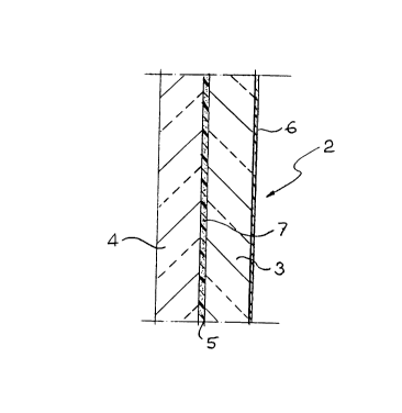
Referring initially to Figures 1 and 2, reference
numeral 1 designates the passenger compartment of an
armoured car having a windscreen 2 formed by two sturdy
glass sheets 3,4 coupled together by an intermediate layer
of a bonding agent 5, in a conventional way. A transparent
polycarbonate or polyester film 6 .is normally applied to
the surface of the inner glass sheet 3 facing towards the
passenger compartment 1.
According to the invention the windshield 2 embodies
within its mass an explosive charg<~: in the case of the
shown example, i.e. in the case of two mutually coupled
CA 02267866 1999-03-31
7
glass sheets, this explosive charge, shown as 7, is
constituted by a uniform and transparent thin layer,
incorporated within the bonding agent layer 5, of water-gel
explosive, for instance of the type produced and marketed
by NITROCHIMIE or by SARDA ESPLOSIV:C INDUSTRIALI SPA.
In case of a multi-layer panel, i.e. in the case of
windows or glass partitions formed by several sheets
coupled to one another, an explosive charge 7 may be
interposed between each layer of adjacent layers.
For activation of the explosive charge 7 an igniter is
provided, which operates a detonator fuse of conventional
type diagrammatically shown as 8 in Figure 1, which is
connected to a manually operable control device 9 provided
with suitable safety protections (not shown in the drawings
since within the skill of the practitioner) against
accidental operation.
In case the car is equipped with inertial passive
safety systems (air bag; safet!,r belt pre-stretching
device ) , the igniter 8 may be autotnatical ly actuated in a
synchronised way with operation of these inertial systems.
In this case a suitable delay device may be provided for
possibly allowing de-activation of the igniter 8 by means
of the manual control 10.
In case of crash or anyway of locking of the car
doors, the windshield 2 according to the invention provides
an immediate escape way following its controlled self-
destruction upon detonation of the explosive charge 7. In
this case in fact the combustion of the explosive charge
rapidly propagates between the two sheets 3,4 causing
micro-shivering thereof substantially within the plane of
the window 2, such as partially depicted on top of the
right side of the windshield 2 in Figure 1. Ejection of any
glass splinters or fragments towards the interior of the
passenger compartment 1 is prevented by the inner film 6.
The explosive charge 7 may consist of usual gunpowders
which, as it is known, can be activated even in the absence
of air, and thus also in wet environment and underwater.
CA 02267866 1999-03-31
8
The volume change caused by firing ~of the explosive charge
and the combustion rapidity are both function of the type
of selected explosive: in this connection the " water-gel"
type explosive is presently considered as preferred
particularly in case the collapsible panel is constituted
by a vehicle window, since this e~;plosive is transparent
and resistant to temperature variations, without any
instability problems, due to insulation, green house effect
and accidental shocks. Moreover such an explosive does not
become dull over the time and is not activated by sparks
produced by any projectile impact.
Naturally in case of non-transparent panels more
common and promptly available explosives can be employed,
such as for instance gunpowder, laminated plastic explosive
and the like.
Figures 3 and 4 show another example in which the
collapsible panel according to the invention is
transparent. In this case the panel. is constituted by an
armoured side window 11 of a motorvehicle, formed by three
sturdy glass sheets 12,13,14 mutually coupled by means of
two intermediate layers of a bonding agent 15,16 in which
respective thin layers of transparent explosive 17,18 are
incorporated, designed to be both acaivated simultaneously
by means of an igniter and/or detonator not shown in the
drawings. In this embodiment peripheral annular channels
19,20 may be provided between the sheets 12,13 and 13,14,
respectively, housing respective explosive charges 21,22.
Upon explosion of the charges 17,:18, detonation of the
annular charges 21,22 releases the window 11 thus collapsed
from the vehicle structure to the aim of providing a fully
open passageway from the interior of the passenger
compartment outwardly and viceversa.
The same effect can be more conveniently achieved
through provision of a greater thickness of the or each
explosive charge 17,18 along the peripheral border of the
window 11, which enables - besides detachment of the
CA 02267866 1999-03-31
9
collapsed window from its support - making the explosion
propagation speed more regular and fast.
It is to be pointed out that in case of armoured
tempered glass panels the shock wave for collapsing thereof
may be generated, instead of an explosive charge
distributed through the panel thickness over its plane, by
a micro-charge concentrated in the weakest point of the
structure, i.e. at the merging zone of two of its edges.
Figures 5 and 6 show another exemplary embodiment of
the invention, in which the collapsible panel consists of a
glass wall 23 of a building structure, for instance of a
public office. Also in this case collapsing of the glass
wall 23 may conveniently be operated by a distributed ( in
case of multi-layer construction) or concentrated in
correspondence of one corner (in case of single-layer
tempered construction) explosive charge, which is
transparent and designed to be fired by an igniter and/or
detonator 24 in turn manually operable by means of a
control member 25.
The glass wall 23 conveniently incorporates a filiform
structure, formed by a plurality of vertical threads 29
connected superiorly to the frame 2'7 of the glass wall 23
and capable to hold, after detonation of the explosive
charge, the glass fragments such as diagrammatically
depicted in Figure 6, as to form a kind of incoherent
curtain thus avoiding piling up of glass shivers on the
ground.
Figure 7 shows a further application of the invention
to a reinforced non-transparent panel for building
construction, generally indicated as 28. This panel 28
comprises an inner load bearing structure 29 which can be
bidimensional or, as in the case of the shown example,
tridimensional with structural nodes 30, and two sheets
31,32 fixed to the load bearing structure 29. Even in this
case the explosive is provided within the mass of the panel
28, and is constituted more particularly by concentrated
charges 33 arranged in correspondence of the structural
CA 02267866 1999-03-31
nodes 30. The explosive charges 33 shall also be activated
through one or more igniter/detonators in turn designed to
be piloted by means of one or more manual controls.
Such a panel can be advantageously employed for the
manufacturing of collapsible wall structures, doors,
bulkheads and the like, to the aim of providing, in case of
need, large passageways capable to safely warrant escape
from the inner environment towards the outer environment
and immediate access from the outaide towards the inner
environment.
It is to be pointed out that th.e embodiments disclosed
with reference to the drawings only constitute a limited
number of possible applications of: the invention, whose
practical working can be advantageously extended to any
separation structure between one and another environments.
In case of application to a collective transportation
vehicle, for instance a bus or a railway body, all windows
thereof may consist of transparent panels according to the
invention, pre-mounted within respective metal or plastic
material frames in turn fixed to the vehicle structure,
each frame carrying an igniter device for the explosive
charge embodied in the respective windows. These igniter
devices may also be designed to be simultaneously actuated,
both from the interior and from the outside of the vehicle,
by means of a suitable key-tool designed to be inserted
into a well visible and accessilble operating socket.
Accordingly escape of the passengers outwardly and entrance
of rescue people inwardly of the vehicle shall be immediate
and through a number of passageways aimultaneously.
Additional examples of advantageous embodiments of the
invention may consist of submerged swing doors and
diaphragm which cannot open owing to piezometric load,
designed to be collapsed so as to perform the task of quick
opening safety valves to prevent damages of hydraulic
plants (for instance of a hydroelectric installation) in
case of anomalous overpressure. Further embodiments may
CA 02267866 1999-03-31
11
consist of walls or windows or large doors with piloted
function of anti-panic collapsing.
Naturally the details of construction and the embodiments
may be widely varied with respect to what has been
disclosed and illustrated, without thereby departing from
the scope of the present invention such as defined in the
appended claims.