Note: Descriptions are shown in the official language in which they were submitted.
CA 02267924 1999-04-O1
- 1 -
MULTI-USER RECEIVING APPARATUS AND CDMA COMMUNICATION SYSTEM
Background of the Invention
1. Field of the Invention
The present invention relates to a CDMA (Code Division
Multiple Access) multi-user receiving apparatus for performing an
interference canceling process in parallel for individual users
on a plurality of stages and for outputting demodulated signals
for the individual users on the last stage, in particular, to a
multi-user receiving apparatus with excellent interference
cancellation characteristics in a small hardware scale.
2. Description of the Related Art
CDMA system using direct sequence (DS) spreading process
(hereinafter referred to as DS-CDMA system) has become attractive
as a multiple access system for a mobile communication system
having a base station and portable mobile stations because of the
probability of remarkable increase of the subscriber capacity.
In the DS-CDMA system, each user signal is spreaded in a wide
frequency band with particular code and transmitted to a
propagation path. On the receiver side, the code-multiplexed
signal is de-spreaded and a desired signal is detected. When
spreaded codes assigned to individual users correlate, they
interfere and the reception characteristics deteriorate.
As an interference canceler, a multi-user receiving apparatus
that cancels such interferences using spreaded codes of all users
and characteristics of propagation paths is known. An example of
such a multi-user receiving apparatus has been disclosed by M.K.
Varanasi and B. Aashang "Multistage Detection in Asynchronous
CA 02267924 1999-04-O1
- 2 -
Code-Division Multiple-Access Communications", IEEE Trans,
Commun., vol. COM-38, No. 4, pp. 509-519, April 1980. In the
example, the first stage circuit demodulates all user signals,
generates interference replicas of the user signals, and subtracts
interference replicas other than an interface replica for a
desired user signal from the received signal. The next stage
circuit demodulates the desired user signal with the output signal
of the first stage circuit. Thus, the demodulated result of the
second stage circuit is improved in comparison with the
demodulated result of the first stage circuit. In the multi-stage
structure, the interference canceling process is repeated a
plurality of times and thereby the interference cancellation
characteristics are improved.
Another related art reference has been disclosed by Fukasawa,
Satoh (T), Kawabe, and Satoh (S) "Structure and Characteristics
of Interference Canceler Based on Estimation of Propagation Path
Using Pilot Signal (translated title)" Journal of The Institute
of Electronics, Information and Communication Engineers, Japan,
B-II Vol. J77-B-II No. 11, November 1994. In the related art
reference, an interference cancellation residual signal
propagation structure is used to simplify the apparatus. In
addition, a determination symbol for each user signal is treated
as a replica. Thus, the hardware scale is reduced. However, in
the detecting process on each stage, interfered propagation path
characteristics estimated on the first stage are used. Thus, when
an estimated error of a propagation path is large, the
interference cancellation characteristics largely deteriorate.
In a recent year, a modification system of such a related art
CA 02267924 1999-04-O1
- 3 -
reference has been proposed. In the system, a propagation path
is estimated on each stage rather than the first stage so as to
suppress the deterioration of interference cancellation
characteristics against a propagation path estimation error. Such
a system has been disclosed by Sawahashi, Miki, Andoh, and Higuchi
"Sequential Channel Estimation Type Serial Canceler Using Pilot
Symbols in DS (Direct Sequence) - CDMA", The Institute of
Electronics, Information and Communication Engineers, Japan,
Wireless Communication System Study Group Technical Report, RCS95-
50, July 1995. In the technical paper, a serial process structure
for sequentially demodulating and canceling interferences of user
signals in the order of higher reception signal levels is used.
Another related art reference has been disclosed by Yoshida and
Atokawa "Sequential Propagation Path Estimation Type CDMA Multi-
Stage Interference Canceler Using Symbol Replica Process" The
Institute of Electronics, Information and Communication Engineers,
Japan, Wireless Communication System Study Group Technical Report,
RCS96-171, February, 1997 (Japanese Patent Laid-Open Publication
No. 10-51353). As with the system proposed by Fukasawa et. al.,
in the system proposed by Yoshida et. al., although a symbol
replica process is performed in an interference cancellation
residual propagation type structure, symbol replicas for
individual user signals are handled so as to sequentially estimate
propagation paths. Thus, the hardware scale can be reduced and
the interference cancellation characteristics can be improved.
Fig. 8 is a block diagram showing an example of the structure
of a CDMA multi-user receiving apparatus disclosed by Yoshida et.
al as Japanese Patent Laid-Open Publication No. 10-51353. In Fig.
CA 02267924 1999-04-O1
- 4 -
8, the apparatus has a plurality of IEUs 112-m-n disposed on a
plurality of stages. IEUs 112-m-n disposed on each stage
correspond to individual user signals. An IEU 112-m-n that
corresponds to the highest hierarchical level user signal performs
an interference canceling process for the lowest hierarchical
level user signal on the preceding (m - 1)-th stage. An IEU 112-
m-n that corresponds to other than the highest hierarchical level
user signal performs an interference canceling process for the (n
- 1)-th hierarchical level user signal. An IEU 112-m-n inputs an
error signal obtained in the interference canceling process and
an interference replica estimated by the IEU 112-(m - 1)-n
corresponding to the same hierarchical level user signal on the
preceding stage, re-estimates the current m-th stage interference
replica, outputs the re-estimated interference replica to an IEU
112-(m + 1)-n corresponding to the same hierarchical level user
signal on the next (m + 1)-th stage, and outputs the result of the
diffusing process as the difference between an interference
replica on the current m-th stage and an interference replica on
the preceding (m - 1)-th stage. IEU 112-M-1, ..., IEU 112-M-N on
the last M-th stage output demodulated results as demodulated user
signals rather than re-estimating interference replicas on the
current M-th stage.
As shown in Fig. 8, the interference canceling process is
performed by M column x N line circuits (where M represents the
number of stages; and N represents the number of user signals).
Reception levels of individual user signals are pre-assigned.
Each user signal is connected to each stage in series
corresponding to a reception level. A demodulating process and
CA 02267924 1999-04-O1
- 5 -
an interpolation canceling process are performed for user signals
in the order from the highest signal level to the lowest signal
level. In this structure, since the interference canceling
process is performed in series, interference replicas can be
sequentially canceled. Thus, although excellent interference
cancellation characteristics are accomplished, the circuit
structure is complicated and a delay in the demodulating process
is large.
Fig. 9 is a block diagram showing another example of the
structure of a CDMA multi-user receiving apparatus. In the
receiving apparatus, the delay of the demodulating process is
small. The interference canceling process is a simple parallel
structure apparatus. The receiving apparatus has multiplying
units disposed on the output side of interference estimating units
IEU. Each multiplying unit multiplies an output signal of the
interference estimating unit by a weighting coefficient a that is
1 or smaller. Thus, the interference cancellation characteristics
are improved.
The CDMA multi-user receiving apparatus shown in Fig. 9 has M
stags (where M is any integer that is two or larger) for
demodulating N user signals (where N is any integer that is 1 or
larger). A first stage interference canceling process circuit
101-1 comprises a delaying unit 103-1, interference estimating
units (IEU) 102-1-1 to 102-1-N, multiplying units 105-1-1 to 105
1-N, and a subtracting unit 104-1. The multiplying units 105-1-1
to 105-1-N multiply output signals of the interference estimating
units 102-1-1 to 102-1-N by a weighting coefficient a,
respectively. The subtracting unit 104-1 subtracts output signals
CA 02267924 1999-04-O1
- 6 -
of the multiplying units 105-1-1 to 105-1-N from an output signal
of the delaying unit 103-1.
An interference estimating unit (IEU) 102-m-n on the m-th
stage (where m is any integer of 1 <_ m _< M) for the n-th user
signal (where n is any integer of 1 _< n <_ N) inputs an
interference cancellation residual signal (an output signal of a
subtracting unit 104-(m - 1)) obtained in the interference
canceling process on the (m - 1)-th stage and a symbol replica (a
replica that is output from an IEU 102-(m - 1)-n) corresponding
to the same user signal on the (m - 1)-th stage, generates an m-th
stage symbol replica, outputs the generated symbol replica to the
(m + 1)-th stage, and outputs a spreaded signal that is the
difference between the m-th stage symbol replica and an (m - 1)-th
stage symbol replica.
A multiplying unit 105-m-n multiplies the output signal of the
interference estimating unit 102-m-n by the weighting coefficient
a. A subtracting unit 104-m subtracts the output signals of the
multiplying units 105-m-n for all user signals from a signal of
which the (m - 1)-th stage interference cancellation residual
signal is delayed by a delaying unit 103-m for the IEU process,
updates the interference cancellation residual signal, and outputs
the resultant signal to the (m + 1)-th stage.
Fig. 2 is a block diagram showing the structure of the
interference estimating unit (IEU) 102-m-n. The IEU 102-m-n has
a plurality of path processing portions (#1 to #K) corresponding
to a plurality of propagation paths as a mufti-path. An inversely
spreading means 11 inputs an (m - 1)-th stage interference
cancellation residual signal (an output signal of a subtracting
CA 02267924 1999-04-O1
_ 7 _
unit 104-(m - 1)). The despreading means 11 performs an
despreading process for a signal corresponding to the each path.
A first adding unit 12 adds an output signal of the despreading
means 11 and an (m - 1)-th stage symbol replica (a replica that
is output from an IEU 102-(m - 1)-n). A detecting unit 13 inputs
an output signal of the first adding unit 12. A propagation path
estimating means 20 detects a propagation path estimation value
corresponding to the each path. A complex conjugate means 21
outputs a complex conjugate value to a multiplying unit 22. The
multiplying unit 22 multiplies the complex conjugate value by the
output signal of the first adding unit 12 so as to demodulate the
signal corresponding to the each path. A second adding unit
14 adds output signals of the detecting units 13 corresponding to
the individual paths (#1 to #K). A decision unit 15 determines
a symbol of an output signal of the second adding unit 14. A
multiplying unit 16 multiplies an output signal of the decision
unit 15 by the propagation path estimation value that is output
from the propagation path estimating means 20 corresponding to the
each path of the paths (#1 to #K) and generates a symbol replica
corresponding to the each path. A subtracting unit 17 subtracts
an (m - 1)-th stage symbol replica from an m-th stage symbol
replica. A spreading means 18 spreads an output signal of the
subtracting unit 17 corresponding to the current(each) path. A
third adding unit 19 adds outputs signals of the spreading means
18 corresponding to the individual paths #1 to #K.
On the first stage, a reception signal as an interference
cancellation residual signal obtained in an (m - 1)-th stage
interference canceling process is used. In addition, on the first
CA 02267924 1999-04-O1
_ g _
stage, zero as a symbol replica corresponding to the same user
signal on the (m - 1)-th stage is used. On the M-th stage, the
interference canceling process is not~performed. In addition,
spread signals as the difference between m-th stage replicas and
(m - 1)-th stage replicas are output. Instead, demodulated
signals are output.
Generally, the characteristics of a parallel process structure
interference canceler are inferior to the characteristics of a
serial process structure interference canceler. This is because
in the serial structure, the interference canceling process can
be performed between user signals on each stage. On the other
hand, in the parallel process, the interference canceling process
can be sequentially performed.
When the interference canceling process is performed for user
signals in the order of the largest signal levels, the
characteristics are further improved. In the interference
canceler shown in Fig. 9, an output signal of each IEU 102-M-N is
multiplies by a real number a that is 1 or smaller so as to
improve the characteristics of the parallel process. The real
number a alleviates the interference canceling process. Thus, all
interferences are not canceled on the first stage. Instead, the
interferences are gradually canceled on a plurality of stages.
In other words, the interference canceling process is alleviated
on the first stage that has a large propagation path estimation
error and a large determined symbol error. Thus, the interference
cancellation error is suppressed. The interference canceling
performance is shared with downstream stages that have a small
propagation path estimation error and a small determined symbol
CA 02267924 1999-04-O1
- 9 -
error. Consequently, the interference cancellation
characteristics can be improved.
In the above-described multi-user receiving apparatuses, with
a parallel structure, characteristics of a serial interference
canceler can be accomplished. However, the characteristics of the
conventional multi-user receiving apparatus are not sufficient in
comparison with those in the serial structure interference
canceler.
Summary of the Invention
An object of the present invention is to provide a mufti-user
receiving apparatus that has interference cancellation
characteristics similar to those of a serial structure
interference canceler and that has a small hardware scale suitable
for a base station and a mobile station of a DS-CDMA communication
system.
The present invention is a mufti-user receiving apparatus for
inputting a CDMA (Code Division Multiple Access) reception signal,
performing an interference canceling process in parallel for each
user signal on an m-th stage of M stages (where m is any integer
of 1 s m <_ M, and M is any integer that is 2 or larger), and
outputting demodulated signals on the M-th stage, comprising a
plurality of IEUs (interference estimating units) disposed
corresponding to the (M - 1) stages and the number of user
signals, and a plurality of subtracting units disposed
corresponding to the (M - 1) stages, wherein each of the IEUs
inputs an interference cancellation residual signal obtained in
an (m - 1)-th stage interference canceling process and a signal
CA 02267924 1999-04-O1
- 10 -
of which a symbol replica corresponding to the same user signal
on the (m - 1)-th stage is weighted with a first weighting
coefficient, generates an m-th stage symbol replica, outputs the
m-th stage symbol replica to the (m + 1)-th stage, and outputs a
spread signal that is the difference between the m-th stage symbol
replica and the (m - 1)-th stage symbol replica weighted with the
first weighting coefficient, and wherein each of the subtracting
units subtracts signals of which the spread signals that are
output from the IEUs on the m-th stage are weighted with a second
weighting coefficient from a signal of which the (m - 1)-th stage
interference cancellation residual signal is delayed by a
predetermined value and outputs the resultant signal to the (m +
1)-th stage.
Each of the IEUs has a plurality of path processing portions
corresponding to a plurality of propagation paths as a multi-path,
each of the path processing portions having despreading means for
inputting the (m - 1)-th stage interference cancellation residual
signal corresponding to the current path and despreading the
interference cancellation residual signal, a first adding unit for
adding an output signal of the despreading means and a signal of
which the (m - 1)-th stage symbol replica is weighted with the
first weighting coefficient, a detecting unit for demodulating an
output signal of the first adding unit with the propagation path
estimation value corresponding to the current path, a second
adding unit for adding the output signals of the detecting units
corresponding to the individual paths, a decision unit for
deciding a symbol of an output signal of the second adding unit,
a multiplying unit for multiplying an output signal of the
CA 02267924 1999-04-O1
- 11 -
decision unit by the propagation path estimation value
corresponding to the current path and generating the m-th stage
symbol replica corresponding to the current path, a subtracting
unit for subtracting a signal of which the (m - 1)-th symbol
replica is weighted with the first weighting coefficient from an
output signal of the multiplying unit, spreading means for
spreading an output signal of the subtracting circuit
corresponding to the current path, and a third adding unit for
adding output signals of the spreading means corresponding to the
individual paths.
A first stage inputs a reception signal as the interference
cancellation residual signal obtained in the (m - 1)-th stage
interference canceling process, wherein zero is used as the (m -
1)-th stage symbol replica of the same user signal, and wherein
the M-th stage outputs demodulated signals rather than performing
the interference canceling process and outputting the m-th stage
symbol replicas and the spread signals.
The first weighting coefficient and the second weight
coefficient are real numbers that are 1 or smaller.
The first weighting coefficient and the second weighting
coefficient on the m-th stage are [1 - (1 - a)"'-1, a], respectively
(where a is a real number that is 1 or smaller).
The first weighting coefficient and the second weighting
coefficient are 1 and a, respectively (where a is a real number
that is 1 or smaller).
The first weighting coefficient and the second weighting
coefficient are a and a, respectively (where a is a real number
that is 1 or smaller).
CA 02267924 1999-04-O1
- 12 -
The first weighting coefficient and the second weighting
coefficient corresponding to an n-th user signal (where n is any
positive integer ) on the m-th stage are [ 1 - ( 1 - a(3"1 ) ( 1 - a(3"z )
. . . ( 1 - a~nm-1) , a~nm] , respectively (where a and (3nm are any real
numbers that are 1 or smaller).
The first weighting coefficient and the second weighting
coefficient corresponding to an n-th user signal (where n is any
positive integer) on the m-th stage are 1 and a(3nm, respectively
(where a and anm are any real numbers that are 1 or smaller).
The first weighting coefficient and the second weighting
coefficient corresponding to an n-th user signal (where n is any
positive integer) on the m-th stage are a~inm-~ and a(3nm,
respectively (where a and ~3nm are any real numbers that are 1 or
smaller).
a is assigned depending on the ratio of signal power to
interference power of each user signal or on the number of user
signals. a is constant for each user signal when the ratio of
signal power to interference power for each user is the same and
the number of user signals does not vary.
~3"m is assigned depending on the ratio of signal power to
interference power of each slot (transmission power control
interval) of each user signal or on the signal power of each slot.
(3"m is assigned depending on each slot of each user signal on each
stage.
(3M, is assigned depending on the likelihood of a determination
symbol of each user signal, on the distance from a symbol
determination point, or on a symbol power. ~3nm is assigned
CA 02267924 1999-04-O1
- 13 -
depending on each symbol of each user signal on each stage.
The present invention is a CDMA (Code Division Multiple
Access) multi-user receiving apparatus for performing an
interference canceling process for all user signals on a plurality
of stages and outputting demodulated signals corresponding to the
user signals, each stage comprising a plurality of interference
estimating units corresponding to a plurality of paths, each of
the interference estimating units having detecting unit for
inputting an interference cancellation residual signal obtained
on the preceding stage and a signal of which a preceding-stage
symbol replica corresponding to the current user signal is
weighted with a first weighting coefficient and demodulating the
resultant signal with a propagation path estimation value of the
current path so as to output a current stage symbol replica and
a spread signal that is the difference between the current stage
symbol replica and the preceding stage symbol replica is spreaded,
a plurality of multiplying units corresponding to the number of
paths, each of the multiplying units generating a signal of which
the current stage symbol replica is weighted by the current stage
first weighting coefficient, a delaying unit for delaying the
preceding stage inference residual signal for a predetermined time
period, and a subtracting unit for subtracting signals of which
the spread signals generated in the interference estimating
portions for all the user signals are weighted with a second
weighting coefficient from an output signal of the delaying unit
and outputting the resultant signal as the next stage interference
cancellation residual signal.
In a CDMA communication system according to the present
CA 02267924 1999-04-O1
- 14 -
invention, the multi-user receiving apparatus is used for a base
station or a mobile station.
The above-described individual means and units allow the
interference cancellation characteristics of the parallel process
structure multi-user receiving apparatus to improve.
These and other objects, features and advantages of the
present invention will become more apparent in light of the
following detailed description of a best mode embodiment thereof,
as illustrated in the accompanying drawings.
Brief Description of Drawinas
Fig. 1 is a block diagram showing the structure of a multi-
user receiving apparatus according to a first embodiment of the
present invention;
Fig. 2 is a block diagram showing the structure of an
interference estimating unit (IEU) according to the present
invention;
Fig. 3 is a block diagram showing the structure of a multi-
user receiving apparatus according to another embodiment of the
present invention;
Figs. 4A to 4C are graphs showing chronological variation of
a received signal power of each user signal according to the
present invention;
Fig . 5 is a graph showing an example of a (3nm determining
method according to the present invention;
Fig. 6 is a graph showing another example of the (3nm
determining method according to the present invention;
Fig. 7 is a graph showing a further example of the (3nm
CA 02267924 1999-04-O1
- 15 -
determining method according to the present invention;
Fig. 8 is a block diagram showing an example of the structure
of a conventional serial structure multi-user receiving apparatus;
and
Fig. 9 is a block diagram showing an example of the structure
of a conventional multi-user receiving apparatus.
Description of Preferred Embodiments
Next, with reference to the accompanying drawings, embodiments
of the present invention will be described.
[First Embodiment]
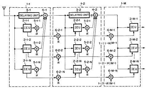
Fig. 1 is a block diagram showing the structure of a multi-
user receiving apparatus according to a first embodiment of the
present invention. The multi-user receiving apparatus comprises
M receiving units 1-1, ... , and 1-M on M stages (where M is any
integer that is 2 or larger). A receiving unit 1-m (where 1 <_ m
<_ M) on each stage comprises N interference estimating units
(referred to as IEU) 2-m-n, a delaying unit 3-m, an adding unit
4-m, a first multiplying unit 6-m-n, and a second multiplying unit
5-m-n. The N IEUs 2-m-n receive N user signals (where N is any
integer that is 1 or larger).
The n interference estimating units (IEU) 2-m-n for n user
signals (where n is any integer of 1 s n _< N) on the m-th stage
(where m is any integer of 1 _< m <_ M) input an interference
cancellation residual signal (an output signal of an adding unit
4-(m - 1)) obtained in the interference canceling process on the
(m - 1)-th stage and signals of which symbol replicas
corresponding to the same user signals on the (m - 1)-th stage are
CA 02267924 1999-04-O1
- 16 -
weighted with a first weight coefficient by first multiplying
units 6-m-n, generates m-th stage symbol replicas, output the
generated symbol replicas to the (m + 1)-th stage, and output
spread signals that are the difference between the m-th stage
symbol replicas and (m - 1)-th stage symbol replicas.
The second multiplying units 5-m-n multiply the output signals
of the IEUs 2-m-n by a second weighting coefficient. The
subtracting unit 4m subtracts the output signals of the
multiplying units 5-m-n for all the user signals from a signal of
which the (m - 1)-th stage interference cancellation residual
signal is delayed for the process period of the IEUs by the
delaying unit 3-m, updates the interference cancellation residual
signal, and outputs the resultant signal to the (m + 1)-th stage.
The structure of the interference estimating unit (IEU) 2-m-n is
the same as that of the conventional IEU shown in Fig. 2.
In Fig. 2, each IEU 2-m-m has a plurality of path processing
portions corresponding to a plurality of paths as a multi-path.
An despreading means 11 corresponding to each path inputs an (m -
1)-th stage interference cancellation residual signal and
inversely spreads the interference cancellation residual signal.
A first adding unit 12 adds an output signal of the despreading
means 11 and an (m - 1)-th stage symbol replica corresponding to
the current path. A detecting unit 13 inputs an output signal of
the first adding unit 12. A complex conjugate means 21 converts
a propagation path estimation value received from a propagation
path estimating means 20 into a complex conjugate corresponding
to the current path. A multiplying unit 22 multiplies the complex
conjugate by the output signal of the first adding unit so as to
CA 02267924 1999-04-O1
- 17 -
demodulate the signal corresponding to the current path.
A second adding unit 14 adds output signals of the detecting
units 13 corresponding to the individual paths. Thus, a path
diversity effect can be obtained.
A decision unit 15 determines a symbol of the output signal of
the second adding unit 14. In QPSK modulation, the decision unit
determines Ich level and Qch level of an orthogonal signal as
(1/J2, 1/J2), (-1/x/2, 1/J2), (-1/~2, -1/J2), and (1/J2, -1/~2)
corresponding to the first quadrant, the second quadrant, the
10 third quadrant, and the fourth quadrant, respectively.
Next, a multiplying unit 16 multiplies the output signal of
the decision unit 15 by a propagation path estimation value
corresponding to the current path and generates an m-th stage
symbol replica.
15 A subtracting unit 17 subtracts the (m - 1)-th stage symbol
replica from the m-th stage symbol replica. A spreading means 18
spreads the output signal of the subtracting unit 17.
Finally, a third adding unit 19 adds the output signals of the
spreading means 18 corresponding to the individual paths. On the
first stage, a signal received from an antenna is used as an
interference cancellation residual signal obtained in the
interference canceling process on the (m - 1)-th stage. In
addition, zero is used as a symbol replica for the same user
signal on the (m - 1)-th stage. On the M-th stage, the
interference canceling process is not performed. In addition,
spread signals that are the difference between the m-th stage
replicas and the (m - 1)th stage replicas are not output.
Instead, demodulated signals corresponding to the individual paths
CA 02267924 1999-04-O1
- 18 -
are output.
In the first embodiment, the second multiplying units 5-m-n
are disposed on the output side of the IEUs 2-m-n. Alternatively,
the second multiplying units 5-m-n may be disposed on the output
side of the subtracting units 17 or the spreading means 18 of the
IEUs 2-m-n.
As described above, unlike with the related art reference, in
the first embodiment, the first multiplying units 6-m-n that
weight a first weighting coefficient are disposed. Thus, since
the weighting process can be optimally performed, the interference
cancellation characteristics can be further improved. The
weighting process is performed so as to gradually cancel
interferences on a plurality of stages. In other words, the
interference canceling process is alleviated on the first stage
that has a large propagation path estimation error and a large
determined symbol error. Thus, the interference cancellation
error is suppressed. The interference canceling performance is
shared with downstream stages that have a small propagation path
estimation error and a small determined symbol error.
Consequently, the interference cancellation characteristics can
be improved.
Next, the first and second weighting effects will be
described. Assuming that a propagation path and a symbol are
ideally estimated, an interference canceling process for a
particular user signal (first user signal) will be described.
Assuming that the received signal level of the first user signal
is 1, since the symbol replica level is defined as a propagation
path estimation value, the symbol replica level R1 on the first
CA 02267924 1999-04-O1
- 19 -
stage is 1 (namely, R1 - 1). Assuming that the weighting
coefficient of the second multiplying unit 5-1-1 is a, the signal
component el of the first user contained in the first stage
interference cancellation residual signal that is output from the
subtracting unit 4-1 is expressed as follows:
el = 1 - aRl - 1 - a ... (1)
Assuming that the weighting coefficient of the first multiplying
unit 6-2-1 on the second stage is a, the symbol replica level R2
on the second stage is expressed as follows:
R2 = e1+aRl = 1
Thus, the signal level of the first user signal is completely
restored. Assuming that the weighting coefficient of the second
multiplying unit 5-2-1 is a, the signal component e2 of the first
user signal contained in the second stage interference
cancellation residual signal is expressed as follows:
e2 = el - a (R2 - aRl) - (1 - a)Z ... (2)
Likewise, when the weighting coefficient of the first multiplying
unit 6 -m-n is 1 - em-~ - 1 - ( 1 - a ) m-1, the m-th stage symbol
replica level Rm becomes 1 (namely, Rm = 1). When the weighting
coefficient of the second multiplying unit 5-m-n is always a, the
signal component em of the first user signal contained in the m-th
stage interference cancellation residual signal is expressed as
follows
em = (1 - a)m ... (3)
When a is 1 or smaller, if m is sufficiently large, em converges
to zero. Thus, the interferences can be completely canceled.
To suppress an interference cancellation error, the
CA 02267924 1999-04-O1
- 20 -
interference canceling process should be gradually performed.
Thus, a should be small. However, since the number of stages M
of the interference canceler is limited, a is optimized depending
on M. It is clear that the first and second weighting
coefficients on the m-th stage are [1 - (1 - a)"'-1, a). However,
to simplify the weighting processes, as the first and second
weighting coefficients, (1, a) or (a, a) are used. However, in
such cases, the characteristics relatively deteriorate.
Although different a values may be used on each stage, it is
known that optimum values of a on individual stages are almost
equal. However, the effect is small although the weighting
processes are complicated.. In such a case, when a on the m-th
stage is expressed as am, the first and second weighting
coefficients are expressed as [ 1 - ( 1 - al) . . . ( 1 - aM-1) , aml -
The present invention is also applied to such a case.
Next, an a determining method will be described. A major
cause of the deterioration of the parallel process structure
interference canceler is a propagation path estimation error on
the first stage. The propagation path estimating error depends
on the ratio of signal power to interference power of each user
signal. Thus, according to the present invention, the value of
a is assigned so that it is proportional to the ratio of signal
power to interference power of each user signal.
In the CDMA system, to solve the problem of transmission
distance, the transmission power is controlled. In this case, the
ratio of signal power to interference power of each user signal
is equally controlled. The ratio is reversely proportional to the
CA 02267924 1999-04-O1
- 21 -
number of user signals. Thus, according to the present invention,
the value of a is assigned so that it is reversely proportional
to the number of user signals. Thus, when the ratio of signal
power to interference power of each user signal is equal and the
number of user signals does not vary, the value of a is constant
for the individual user signals.
[Second Embodiment]
Fig. 3 is a block diagram showing the structure of a multi-
user receiving apparatus according to a second embodiment of the
present invention. The structure of the multi-user receiving
apparatus according to the second embodiment is almost the same
as the structure of the multi-user receiving apparatus according
to the first embodiment except that a first weighting coefficient
of first multiplying units 36-m-n and a second weighting
coefficient of second multiplying units 35-m-n of the second
embodiment are different from those according to the first
embodiment.
The first and second weighting coefficients of the ffirst and
second multiplying units are [ 1 - ( 1 - a(3nO ( 1 - a(3"z) . . . ( 1 -
a~i"",_
1) , a(3M,] .
In this case, the value of a is the same as that of the first
embodiment shown in Fig. 1. The value of ~3"", depends on each stage
and each user signal. Thus, the value of (3M, is an adaptive value
that chronologically varies. The first weighting coefficient is
a product of a constant weighting coefficient a and an adaptive
weighting coefficient ~3mn. Thus, the weighting process can be
flexibly performed. In the weighting method, the signal component
CA 02267924 1999-04-O1
- 22 -
em of the first user signal contained in the m-th stage
interference cancellation residual signal is expressed as follows:
em = ( 1. - a~nl ) ( 1 - a~nz ) . - . ( 1 - a~nm) . . . (
When a and (3nm are real numbers that are 1 or smaller, they
converge to 0. The weighting method according to the second
embodiment is different from that according to the first
embodiment in that (3nm varies on each stage and for each user
signal. Thus, the interference canceling process for each user
signal can be independently controlled.
In other words, when a user signal has a large interference
cancellation error due to a propagation path estimation error of
an IEU 32-m-n and a symbol error, the interference canceling
process is gradually performed so as to suppress the
characteristics from deteriorating. The interferences are
canceled on downstream stages.
To simplify the first weighting process , ( 1, a~3nm) and (et(3nm -
1, a~nm) can be used.
Next, a ~3nm determining method will be described. When the
transmission power is ideally controlled, the ratio of signal
power to interference power for each user signal is equally
controlled. However, actually, a transmission power control error
exists. Figs. 4A to 4C are graphs showing received signal powers
of individual user signals in the case that a transmission power
control error exists. Since the transmission power is controlled
slot by slot, the received signal power varies slot by slot.
Since the transmission power control error depends on each user
signal, the ratio of signal power to interference power at each
CA 02267924 1999-04-O1
- 23 -
slot varies for each user signal. Figs. 4A to 4C show the state
that the received signal power of each user signal #1 to #N varies
against an average signal power slot by slot. Thus, according to
the present invention, the value of (3nm is assigned so that it is
proportional to the ratio of signal power to interference power
of each slot.
As a real method, each slot signal power of each user signal
is measured. An average signal power of all user signals is
obtained. Corresponding to the ratio of each slot signal power
of each user signal to average power of all user signals, ~inm is
determined. In other words, the following relations are
satisfied:
~nm = SQRT ( Pnm ~ ( ( Plm + P2m + . . . + PNm ) ~ IV ) ) ( (3nm = 1 ( ~nm >-
1 )
where P"m is each slot signal power of a n-th user signal on an m-
th stage. In this case, (3nm is calculated with SQRT.
Alternatively, any nonlinear scale can be used.
When the number of user signals is sufficiently large, the
average power of all the user signals is almost equal to the
average signal power of one user signal. Thus, each slot signal
power of each user may be normalized with the average signal
power. In other words, the following relations are satisfied:
~nm = SQRT ( Pnm ~ A ( Pnm ) ) . ~nm = 1 ( ~nm Z 1 )
where A(P"m) is the average signal power of the n-th user signal
on the m-th stage. Since ~3nm depends on each slot of each user
signal, the deterioration of characteristics due to fluctuation
of signal powers of individual user signals corresponding to a
transmission power control error can be suppressed.
CA 02267924 1999-04-O1
- 24 -
Next, another (3"m determining method will be described. In the
method, an interference cancellation error due to a determination
symbol error can be suppressed. In a nonlinear interference
canceler corresponding to the symbol determining method, a
determination symbol error results in a large interference
cancellation error. For example, when a symbol error takes place
in BPSK, a symbol interference that is 6 dB higher than the
original symbol occurs rather than canceling interference.
Thus, when a symbol determination error takes place, if the
interference canceling process is not performed, characteristics
improve. However, when a signal is demodulated, a symbol
determination error cannot be detected.
Thus, according to the present invention, the likelihood of a
determination symbol is estimated with a pre-determined reception
symbol that has been normalized with an average signal power.
When the likelihood is small and thereby the probability of
occurrence of a determination symbol error is high, a small value
is assigned to
Fig. 5 is a graph showing an example of a (3nm determining
method corresponding to the likelihood. In Fig. 5, coordinates
of Ich level and Qch level of an orthogonal signal are
illustrated. Thus, in Fig. 5, the relation between a reception
symbol and coefficient ~3 is represented. In the method, the
likelihood is calculated with the reception symbol and the ratio
of signal power to interference power.
Likelihood - (probability of which determination symbol is
received as reception symbol) / (sum of probability of which each
modulation symbol in QPSK is received as reception symbol)
CA 02267924 1999-04-O1
- 25 -
In QPSK, the likelihood at the center of the coordinate is
0.25. The likelihood at the symbol determination point is close
to 1. The likelihood is low in the vicinity of the center of the
coordinates and on I and Q axes. In Fig. 5, an upper right area
of ~3nm = 1 for a 50 ~ symbol is delimited with a dashed line. The
area can be freely set.
As another method, phase likelihood is used.
Phase likelihood = (phase of determination symbol) - (phase
of reception symbol)
In QPSK, the phase likelihood ranges from 0 to 45° . The phase
likelihood should be converted into ~3nm. For simplicity, when the
phase likelihood is 0°, ~3nm is 1; when the phase likelihood is
45°,
~nm 1S 0.
Such methods are not practical because complicated
calculations are required for obtaining likelihood. As a simple
method for determining ~inm, as IQ coordinates shown in Fig. 6, the
distance from a symbol determination point is used. When a
reception symbol is present at the symbol determination point, (3nm
is assigned so that it is reversely proportional to the distance
to the symbol determination point. For example, when the
reception symbol is present at the symbol determination point, (3M,
- 1. When the reception symbol is present at the center of the
coordinates, anm - 0. In an upper right area delimited with a
dashed line, (3nm = 1. Since these characteristics are similar to
a likelihood curve, the characteristics can be effectively used.
Next, with reference to Fig. 7, another (3nm determining method
that uses a symbol power will be described on IQ coordinates. In
CA 02267924 1999-04-O1
- 26 -
the method, the following relations are satisfied:
Nnm = SQRT ( Pnm ~ A ( Pnm ) ) . anm = 1 ( ~nm ? 1 )
where Pnm is the symbol power at particular time of the n-th user
on the m-th stage; and A(Pnm) is the average signal power. In this
case, ~nm is calculated with SQRT. Alternatively, any nonlinear
scale can be used. Thus, when (3nm varies on each stage, for each
user signal, for each symbol, the deterioration of characteristics
due to a determination symbol error can be suppressed.
The above-described methods are only examples of the present
invention. In other words, there will be many variations of the
above-described methods.
Figs. 1 and 2 show the structures of which interferences of
all user signals are canceled in parallel. However, the present
invention can be applied to a serial-parallel hybrid structure
interference canceler of which a parallel process is partly
performed and a serial process is performed for a parallel process
user signal. In this case, the above-described effects can be
obtained. Such a structure is included in the scope of the
present invention.
It should be noted that the above-described embodiments may be
applied to a short code spread modulation of which a spread code
period is equal to a symbol period or to a long code spread
modulation of which a spread code period is longer than a symbol
period.
As described above, according to the present invention, a
multi-user receiving apparatus with a parallel process structure
that is simple and that is a small delay of demodulating process
is provided. In addition, a symbol replica generated in an
CA 02267924 1999-04-O1
- 27 -
interference estimating unit is weighted with a first weighting
coefficient. A interference cancellation residual signal is
weighted with a second weighting coefficient. The weighting
coefficients are varied for each user signal. Thus, the
interference cancellation characteristics can be improved as with
the serial structure.
In the mufti-user receiving apparatus according to the present
invention, the characteristics of the interference canceler with
parallel process structure can be further improved as with a
serial structure interference canceler.
Although the present invention has been shown and described
with respect to a best mode embodiment thereof, it should be
understood by those skilled in the art that the foregoing and
various other changes, omissions, and additions in the form and
detail thereof may be made therein without departing from the
spirit and scope of the present invention.