Note: Descriptions are shown in the official language in which they were submitted.
CA 02267986 1999-04-06
Docket No. 1423-405P
TELESCOPING SYSTEM WITH MULTIPLE
SINGLE-STAGE TELESCOPIC CYLINDERS
BACKGROUND OF THE II~IVENTION
1. Field of the Invention
The present invention relates tc> a telescoping system for
selectively extending and retracting telescopic sections of a
multi-section telescoping structure with respect to one
another; and more particularly, to ;~ telescoping system with
multiple single-stage telescopic cylinders.
2.~ Description of Related Art
Many prior art telescoping :systems include multiple
single-stage telescopic cylinders or a single multi-stage
telescopic cylinder for extending and retracting multi-section
telescopic structures such as mufti-section booms. A multi
stage telescopic cylinder includes a .plurality of cylinders and
pistons arranged in a telescopic manner, one within the other.
In a telescoping system which includes multiple single-stage
telescopic cylinders, the telf~scopic cylinders are
hydraulically connected in series. U.S. Patent No. 4,733,598
to Innes discloses such a telescoping system.
Unfortunately, telescoping systems such as Innes do not
allow independent control over retraction and extension of each
single-stage telescopic cylinder. Instead, the extension and
retraction of the telescoping system is predetermined. Namely,
the order in which the single-stage telescopic cylinders extend
and retract is predetermined. Furthermore, each telescopic
cylinder in the system fully retracts or extends. Accordingly,
CA 02267986 2003-03-18
2
systems such as Innes are not flexible, and each time a user
wants to change, for example, the order in which the telescopic
cylinders extend and retract, a different telescoping system
is required.
In accorr~ance with an embodiment of the present
invention there is provided a telescoping system, comprising:
a first tele cylinder including a first cylinder, a first rod
having a first and second end, a first piston head connected
to said first end of said first rod and disposed in said second
cylinder, said second end of said first rod including first,
second and third ports: said first rod, said first piston head
and said first cylinder defining a first chamber; said first
cylinder and said first piston head defining a second chamber;
said first rod and said first piston head including a first
passageway communicating said first port and said first chamber
and a second passageway communicating said third port and said
second chamber; said first cylinder and said first rod
including a third passageway communicating with said second
ports said first cylinder including a fourth passageway
communicating with said first chambers a second tele cylinder
including a second cylinder, a second rod having a third and
fourth end, a second piston head connected to said third end
of said second rod and disposed in said second cylinder, said
fourth end of said second rod including a fourth and fifth
ports a first line connecting said fourth port and said third
passageway: a second line connecting said fifth port and said
fourth passageway said second rod, said second piston head and
said second cylinder defining a third chamber; said second
cylinder and said second piston head defining a fourth chamber;
said second rod including a fifth passageway communicating said
CA 02267986 2003-03-18
3
third chamber and said fifth port; and said second rod and said
second piston head including a sixth passageway communicating
said fourth port and said fourth chamber.
There is also provided, according to one embodiment,
a telescoping system, comprising: a first fluid motor having
a first extension chamber and a first retraction chamber; a
second fluid motor having a second extension chamber and a
second retraction chambers means for providing fluid
communication between said first fluid motor and said second
fluid motor; and wherein said first fluid motor includes a
first extension supply port in fluid communication with said
first extension chamber, a second extension port in fluid
communication with said second extension chamber via said
providing means, and a retraction supply port in fluid
communication with said~first retraction chamber and in fluid
communication with said second retraction chamber via said
providing means.
A telescoping system, according to another
embodiment, comprises: a first fluid motor having a first
extension chamber and a first retraction chamber; a second
fluid motor having a second extension chamber and a second
retraction chamber; supply means for controlling supply of
hydraulic fluid to said first fluid motor and between said
first fluid motor and said second fluid motor such that said
first and second fluid motors operate independently.
Other features, and characteristics of the present
invention; methods, operation, and functions of the related
elements of the structure: combination of parts; and economies
of manufacture will become apparent from the following detailed
description of the preferred embodiments and
CA 02267986 1999-04-06
Docket No. 1423-405 4
accompanying drawings, all of which form a part of this
specification, wherein like reference numerals designate
corresponding parts in the various figures.
BRIEF DESCRIPTION OFTINE DRAWIN
The present invention will become more fully understood
from the detailed description given hereinbelow and the
accompanying drawings which are given by way of illustration
only, and thus are not limitative of the present invention, and
wherein:
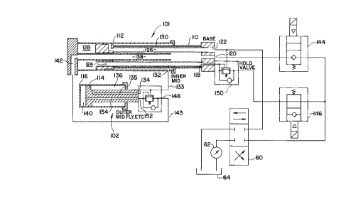
Fig. 1 illustrates a longitudinal cross-section of one
embodiment of a telescoping system including multiple single-
stage telescopic cylinders according t:o the present invention.
DETAILED DESCRIPTION OF THE PREFERRED EMBODIMENTS
Fig. 1 illustrates a longitudinal cross-section of one
embodiment of a telescoping system including multiple single
stage telescopic cylinders according to the present invention.
As shown, the telescoping system includes a first tele cylinder
101 and a second tele cylinder 102. The first tele cylinder
101 includes a first piston 110 and a first cylinder 112. The
second tele cylinder 102 includes a second piston 114 and a
second cylinder 116.
Preferably, one end of the first piston 110 is mounted to
the base section of a multi-section boom structure. A multi-
section telescoping boom will be described as the multi-section
telescoping structure for purposes o:E discussion. The multi-
section boom structure can be a 3, 4, or 5 section boom. Fig.
1 illustrates the connections between the first and second tele
cylinders 101 and 102 and a five section boom. Specifically,
the first piston 110 is connected to the base section, the
first cylinder 112 is connected to the inner mid section, and
the second cylinder 116 is connected t.o the center mid section.
The first rod 110 has a first port 118, a second port 120,
and a common port 122 formed in the rod end thereof . The rod
and the piston head of the first rod 110 include a first
passageway 124 formed therein such that hydraulic fluid
CA 02267986 1999-04-06
Docket No. 1423-405 5
entering the first rod 110 via the first port 118 communicates
with a first chamber 128. The rod a.nd the piston head of the
first piston 110 also include a second passageway 126 which
allows fluid communication between the common port 122 and a
second chamber 130.
As shown in Fig. 1, the first cylinder 112 includes a
single barrel cylindrical outer wall. with a third passageway
132 to the second chamber 130 foamed therein. Further, a
cylindrical inner wall of the first cylinder 112 forms a
trombone tube 138 extending through the piston head of the
first piston 110 and into the rod of the first piston 110. The
trombone tube 138 provides a passageway between the second port
120 and a fourth passageway 142 in thE: first cylinder 112.
The second piston 114 has a fourth port 134 and a fifth
port 152 in one end thereof. A fifth passageway 135 in the
second piston 114 provides fluid communication between the
fourth port 134 and a third chamber 136, and a sixth passageway
154 in the second piston 114 provides fluid communication
between the fifth port 152 and a fourth chamber 140. A first
line 133 (e.g., a hose) connects thc~ third passageway 132 to
the fourth port 134. The third passageway 132, the first line
133, the fourth port 134 and the fifth passageway 135 allow
fluid communication between the second chamber 130 and the
third chamber 136.
A first holding valve 148 is disposed at the fifth port
152. The first holding valve 148 allows hydraulic fluid to
freely flow into the fourth port 152, but does not allow
hydraulic fluid to flow out unless hydraulic fluid is applied
to a bias input thereof. A connection exists, as shown by
dashed lines, between the first line 133 and the bias input of
the first holding valve 148. The hydraulic fluid in the first
line 133 can pilot the first holding valve 148 open to allow
hydraulic fluid to flow out of the i=fifth port 152. A second
line 143 connects the fourth passageway 142 with the first
holding valve 148. Accordingly, the trombone tube 138, the
fourth passageway 142, the second line 143, the first holding
CA 02267986 1999-04-06
Docket No. 1423-405 6
valve 148, the fifth port 152, and the sixth passageway 154
allow fluid communication between the second port 120 and the
fourth chamber 140.
A second holding valve 150 is disposed at the first port
118. The second holding valve 148 allows hydraulic fluid to
freely flow into the first port 118, but only allows hydraulic
fluid to flow out of the first port 118 when hydraulic fluid is
received at its bias input.
A first solenoid valve 144 regulates the supply of
hydraulic fluid to the second port 120; and therefore, the
first holding valve 148. The fir:~t solenoid valve 144 is
closed in a de-energized state. A second solenoid valve 146
controls the supply of hydraulic fluid to the second holding
valve 150, and is open in a de-energized state. Both the first
and second solenoid valves 144 and 146 are connected to a first
control port of a control valve 60. A second control port of
the control valve 60 is connected to the common port 122 and
the bias input of the second holding valve 150.
The control valve 60 is a tri-state control valve. In a
first state, the hydraulic fluid supplied to the control valve
60 by a pump 62 is output from the first control port (i.e., to
the first and second solenoid valves 144 and 146), while the
hydraulic fluid at the second control port is exhausted to a
reservoir 64. In a second state,. no hydraulic fluid is
supplied to or exhausted from either the first or second
control ports. In the third state, the hydraulic fluid from
the pump 62 is supplied to the second control port (i.e., the
common port 122 and the bias input of: the second holding valve
150), while the hydraulic fluid at t:he first control port is
exhausted to the reservoir 64.
The operation of the telescoping system shown in Fig. 1
will now be described. The telescopic cylinder according to
the present invention has two modes of operation: sequenced and
synchronized.
Sequenced operation will be discussed first. Assuming
that the telescopic cylinder illustrated in Fig. 1 is fully
CA 02267986 1999-04-06
Docket No. 1423-405 7
retracted, the first and second solE:noid valves 144, 146 are
de-energized, and the control valve 60 is placed in the first
state. In the de-energized state, th~~ first solenoid valve 144
is closed and the second solenoid valve 146 is open.
Consequently, hydraulic fluid flows via the second solenoid
valve 146 through the second holding valve 150 into the first
port 118. The hydraulic fluid supplied to the first port 118
flows via the first passageway 124 into the first chamber 128,
and exerts a force on the piston head of the second piston 114.
As a result, the first cylinder 112 will extend.
Once fully stroked, the first solenoid valve 144 and the
second solenoid valve 146 are energized. The fully stroked
position can be detected by, for example, a proximity switch
(not shown). Energizing the first and second solenoid valves
144 and 146 causes the first solenoid valve 144 to open and the
second solenoid valve 146 to close. :Hydraulic fluid then flows
through the first solenoid valve 144 <~nd enters the second port
120. The hydraulic fluid flowing into the second port 120
enters the fourth chamber 140 via the trombone tube 138, the
fifth passageway 142, the line 143, the first holding valve
148, the fourth port 152, and the sixth passageway 154. This
hydraulic fluid exerts pressure on the second cylinder 116
causing the second cylinder 116 to extend. Once fully stroked,
the first solenoid valve 144 is de-energized. Again, the fully
stroked position can be detected using a proximity switch (not
shown) .
To retract the telescopic cylinder illustrated in Fig. 1,
the first solenoid valve 144 is opE:ned, the second solenoid
valve 146 is closed, and the control valve 60 is placed in the
third state. Accordingly, hydraulic pressure is supplied to
the common port 122 and the bias input of the second holding
valve 150. The supply of hydraulic fluid pilots the second
holding valve 150 open to allow hydraulic fluid to flow out of
the first port 118.
The hydraulic fluid supplied to the common port 122 flows
into the second chamber 130 via the second passageway 126. The
CA 02267986 1999-04-06
Docket No. 1423-405 8
force exerted upon the first cylinder 112 by the hydraulic
fluid, however, does not cause the first cylinder 112 to
retract since the second solenoid valve 146 is maintained in
the closed state. Instead, the hydraulic fluid flows into the
third chamber 136 via the third passageway 132, the line 133,
and the fourth passageway 134. The hydraulic fluid flowing
through the line 133 is supplied to the bias input of the first
holding valve 148, and pilots the first holding valve 148 open.
The hydraulic fluid in the third chamber 136 exerts a force on
the second cylinder 116 causing the' second cylinder 116 to
retract since the first holding valve 148 and first solenoid
valve 144 are open allowing hydraulic fluid to flow
therethrough.
Once the second cylinder 116 l:~as fully retracted, the
first solenoid valve 144 is closed and the second solenoid
valve 146 is opened. In this state, hydraulic fluid is allowed
to flow through the second solenoid valve 146, such that the
force exerted on the first cylinder 112 by the hydraulic fluid
in the second chamber 130 causes the first cylinder 112 to
retract.
In the synchronized mode of operation, the first and
second solenoid valves 144 and 146 are switched between the
open and closed states at predetermined positional settings to
extend the first cylinder 112 and the second cylinder 116 in a
synchronized manner. Likewise, once the hydraulic fluid has
been supplied to the common port 1:?2, the first and second
solenoid valves 144 and 146 are also switched between the open
and closed state in order to retract the first and second
cylinders 112 and 116 in a synchronized manner.
In the telescoping system according to the present
invention, the hydraulic connections are made such that no long
hoses, which must extend and retract with the operation of the
telescopic cylinder, are required, and the hose reels therefor
are likewise eliminated.
The holding valve, solenoid valve and single control valve
hydraulic control system in the telescoping system according to
CA 02267986 1999-04-06
Docket No. 1423-405 9
the present invention permits independent control over each
single stage telescopic cylinder. Accordingly, the telescoping
system provides great flexibility.
The invention being thus descr:Lbed, it will be obvious
that the same may be varied in many ways. Such variations are
not to be regarded as a departure from the spirit and scope of
the invention, and all such modifications as would be obvious
to one skilled in the art are intended to be included within
the scope of the following claims.