Note: Descriptions are shown in the official language in which they were submitted.
CA 02267988 1999-04-06
WO 98I15112 PCT/US97/17974
1
DYNAMIC REAL TIME EXERCISE VIDEO APPARATUS AND
METHOD
This application claims the benefit of U.S. Provisional Patent
Application Serial No. 60-00a239, filed October 11, 1995.
BACKGROUND OF THE INVENTION
Field of the Invention
This invention ;enerally relates to exercise machines and exercise monitoring
devices and more particularly to an interactive video coupled exercise
apparatus.
Description of the Related Art
Moderate exercise, at an appropriate heart rate, is widely regarded today as
an
excellent way to improve one's health when performed on a regular and
firequent
basis. Many people prefer individual activities such as cycling, running,
rowing, or
skiing. These activities are usually performed during good weather conditions.
During foul weather conditions, in order to maintain a regular exercise
program, many
people use stationary exercise devices such as stationary bikes or bike
stands,
treadmills, ski machines and stair steppers. Same representative exercise
machines
are disclosed in U.S. Patent Nos. 4,938,474; 4,949,993; 5,089,960; 5,207,621;
and
5,403,2S2.
One of the drawbacks of using stationary exercise equipment is that the
scenery, typically a wall or window, viewed during the exercise period doesn't
change. This type of exercising is boring. Typically, the user can counter
boredom
by watching TV, playing a video game, or simply letting his/her mind wander.
' However, these methods don't provide much real incentive for user
participation and
an enhanced exercise experience.
One solution is to make a video game interactive with the exercise device and
the aerobic level of the user. A number of approaches to this end have been
CA 02267988 1999-04-06
WO 98/15112 PCTIUS97I17974
2
proposed. U. S. Patent Nos. 4,711,447 to suggests utilizing an exercise
machine to
move simulated weapons on a video screen in relation to targets on a video
screen into
position so that the targets may be shot. U.S. Patent No. 4,674.741 to
Pasierb, Jr. et
al discloses a rowing machine with a video display that relates the distance
between a
pacer figure and a rowing figure to the user's stroke motion.
U.S. Patent No. 5, 362,069 to Hall-Tipping discloses an apparatus which
couples an exercise device to a video game in which the heart rate of the user
(aerobic
level) and the exercise device output level (bicycle pedal rate) are coupled
to a
standard video game in addition to the normal game hand controls. The video
game
difficulty and game piece movement level as well as the pedal resistance are
changed
in response to the heart rate signal in order to keep the user exercising at
the desired or
programmed rate.
U.S. Patent No. ~, 385.519 to Hsu et aI discloses a computer controlled
running machine which tilts and changes endless belt speed in synchronization
with a
computer CD programmed with various road conditions and sounds. The CD
provides visual images and sounds of the road to the user via a head mounted
visual-
acoustic mask. There is no mechanism to vary the visual or audio effects due
to the
activity of the user.
U.S. Patent No. 5.246,4l 1 to Rackman et al discloses an exercise bike coupled
through a speed sensor and a noise generator to a TV to introduce noise into
the TV
channel if the user exercises below a preset level or above another preset
level.
U.S. Patent No. 5,240,417 to Smithson et aI discloses an arcade type bicycle
racing simulation device which visually portrays, in an animated video scene,
a rider's
movements on an exercise bike in response to a variable terrain in the
computer
generated animated video. Sensors on the bicycle sense pedal speed and leaning
position and feed this information to a computer which uses computer animation
to
change the position of an animated figure in the video scene of the track.
U.S. Patent No. 5,277,678 to Friedebach et al discloses a skiing simulation
device that is coupled to a video display which shows images of the terrain
that the
skier is moving over. The video system such as a video tape may send control
signals
CA 02267988 1999-04-06
WO 98I15112 PCT/US97/17974
-,
J
to servo-motors to increase or decrease resistance to the movement of the
skates
depending on the viewed terrain on the tape. U.S. patent No. 5,489,249 to
Brewer et al
discloses another exercise machine control system coupled to a videotape
player via
the player's audio and/or video track to control the exercise machine
resistance.
However, there is no interaction with or control of the video in response to
the user's
efforts in these patents.
U.S. Patent No. S,308,296 discloses an interactive exercise device that
utilizes
interactive compact disc driven adventure scenarios and the user's physical
responses
to generate different outcomes to the computer generated scenarios presented
on the
video monitor. Speed and timing of exercise actions are required in order to
advance
through the scenario program.
Another simulated environment is displayed on a video display coupled to an
exercise apparatus in U.S. Patent Nos. 5,462,503 to Benjamin et al and
5,466,200 to
Ulrich et al. These patents disclose a networked computer generated
environment
through which one or more users navigate on an exercise device such as a
recumbent
exercise bicycle with pedals and a steering control. The computer controls the
resistance against pedaling and generates display of the relative positions of
the
networked users in the computer generated environment.
Each of these prior art references, that utilizes video scenes to enhance the
exercise experience, relies on computer generated video scenes in order to
simulate
the visual progress of the user passing through the displayed visual
environment.
Although some video systems coupled to exercise devices utilize real-time
video such
as videotapes of wild scenic country or races, etc., none of these systems
interactively
control the speed of the user passing through the viewed "windows" or scenery.
SUMMARY OF THE INVENTION
It is therefore an object of the present invention to provide an interactive
exercise monitoring apparatus in which the speed of the exercise device
controls the
speed of a real-time video frame sequence displayed on a video monitor such as
a TV
CA 02267988 1999-04-06
WO 98I15112 PCT/1JS97/17974
4
by a prerecorded video player device so that the user experiences the
sensation of
actually moving through the video environment in proportion to his/her
exercise rate.
It is another object of the invention to provide an apparatus for converting a
conventional exercise apparatus and a conventional video player coupled to a
television into an interactive real time exercise monitoring video system.
It is another object of the invention to provide a prerecorded video disc for
use
with an apparatus for converting a prerecorded video CD player coupled to a
television or video monitor into an interactive real time exercise monitoring
video
system.
It is another object of the invention to provide a method for independently
varying the frame rate of real-time video playback frame sequences.
It is another object of the invention to provide a method of independently
varying the frame display rate of real-time video sequences in conventional
video
playback machines in response to a user's rate of exercise independently of
the audio
playback rate.
It is another object of the invention to dynamically control the frame rate of
real-time video playback in response to a user's exercise repetition rate
without
changing the pitch of an audio stream associated with the video frame
sequence.
It is a still further object of the invention to maintain the flow of the
sound
from a sound track associated with a real time video sequence independent of
the
video frame display rate.
The apparatus in accordance with one preferred embodiment of the invention
is designed for use with a bicycle mounted on a conventional stationary
exercise stand
in which the rear wheel is laterally supported such that the wheel engages a
resistance
roller. The bicycle is outfitted with a handlebar mounted cycle computer. For
example, a conventional heart rate and cycle speed computer system such as the
Vetta
VHR25 may be used.
The Vetta VHR25 cyclocomputer is removably fastened to a mount secured to
the handlebar of the bicycle. The rear wheel of the bicycle is fitted with a
magnetic
reed switch pickup for the handlebar mounted cyclocomputer and the user wears
a
CA 02267988 1999-04-06
WO 98/15112 PCT/US97/17974
heart rate transmitter strap band around his/her chest in this commercially
available
cyclocomputer system. The receiver is enclosed within the cyclocomputer.
The apparatus in accordance with the present invention basically comprises the
VHRZS wheel pickup, an interface unit mounted on the cyciocomputer handlebar
5 mount in place of the cyclocomputer, a conventional video game controller
connected
to the interface unit and connected to a video game CD player, a video monitor
or a
conventional television receiver connected to the video game player, and a
prerecorded video CD playable in the video game player. The interface unit
converts
the cyclocomputer input signals into outputs that can be used in the video
game
player. The game controller is preferably removably mounted to the bicycle
handlebar via the interface unit so as to be readily accessible to the bicycle
rider
during e~cercise.
The prerecorded video CD preferably contains a software program which
modif es the conventional video player control program . The software program
on
the CD modifies this video player control program based on the signal from the
interface unit or signal converter mounted on the bicycle handlebar. The
software
program effectively delays or speeds up the effective frame sequence
transmission
rate from the player to the video monitor or TV in response to the signal from
the
interface unit, which is proportional to the speed of the bicycle, i.e. the
rate of
exercise.
In real time video recording, as opposed to computer generated animated video
production, each real time video frame receives a unique time stamp and
duration
stamp during videotape recording. These time and duration stamps are also
recorded
on the CD during the recording of the video on the CD. The video control
program
in the video CD player then uses the unique time stamp and duration stamp
associated
with each video frame recorded on the CD to transmit the sequence of video
frames at
the proper time and in proper sequence to the video monitor or television.
The system and apparatus in accordance with the present invention utilizes a
signal proportional to a user's exercise rate (speed) to dynamically generate
modification values to modify the duration stamp values actually utilized by
the
CA 02267988 1999-04-06
WO 98I15112 PCT/L1S97/17974
6 -
player in order to effectively speed up or slow down the frame sequence rate
in
proportion to the user's exercise rate . The result, when viewed by the user
is the
visual perception of actually traveling through the scenery depicted in the
video
sequence.
The exercise level signal in the illustrated embodiment is generated from
input
from the wheel reed switch mentioned above. A wheel magnet is fastened to one
of
the wheel spokes. A reed switch is fastened to one of the rear forks at a
position
opposite the wheel magnet switch. Each revolution of the bicycle wheel causes
the
reed switch to momentarily close as the magnet passes by. This closure is
sensed by
the interface unit circuitry which counts the time between reed switch
closures, which
is therefore proportional to the speed of the bicycle. This signal or count is
fed
through the conventional video game controller pad through the tandem video
controller port and then to the video planer where it is used as the basis to
modify the
duration time stamp of each video frame in accordance with the sofrivare
program.
1 ~ Functionally, the software program basically converts this speed signal to
a
modification value which is added to the unique duration time stamp for each
successive video frame. The modification value changes as the user's speed
changes.
Therefore, the software program queries the modification value register and
functionally modifies the next frame's time stamp before sending each video
frame to
the monitor for display.
The method in accordance with the present invention of controlling a video
frame sequencing rate in a video playback sequence in which each video frame
has a
unique frame time stamp comprises the following steps:
a) setting time offset to current clock time;
b) displaying a current video frame;
c) accessing a frame time stamp value and a duration time stamp value
associated with said current video frame;
d) accessing a user variable external signal;
e) determining an adjustment value from predetermined criteria compared to
the external signal;
CA 02267988 1999-04-06
WO 98I15112 PCT/US97/17974
7
f} adding the adjustment value, the duration time stamp value, and the time
offset to the frame time stamp value to generate a next frame time value;
g) displaying a next frame when current clock time exceeds said the frame
time value; and
h) repeating steps a) through g) for each successive video frame in the
sequence of video frames.
The step of displaying a frame more particularly includes the steps of
i) comparing current clock time to the next frame time value;
ii) if the current clock time equals or exceeds the next frame time value,
then
decompressing a next video frame into a display buffer; and
iii) adding the adjustment factor to the time offset, which maintains a
running
track of adjustments made to the duration stamps during execution of the video
frame
sequence.
The method of the present invention and the apparatus may be used with any
exercise device which can provide a signal representative of the user's
exercise rate.
For example, the bicycle may be replaced by a cross country ski machine, a
stationary
running machine, a stair stepper, or a rowing machine. The storage medium such
as a
video CD used in the player in accordance with the present invention may have
any
number of video sequences recorded thereon, and it would be particularly
desirable if
the video sequence corresponded to the particular type of exercise device. For
example, a road or trail passage sequence would be appropriate for a bicycle
exercise
device. A climbing sequence might be appropriate for a stair stepper. Both
video
sequences could be recorded on the storage medium so that either exercise
device
could be used.
The audio which is recorded on the CD along with the video frame sequence
may be recorded as a separate track or in discrete audio data chunks
associated and
keyed to each video frame. The method of varying the video display rate in
accordance with the invention does not affect the reproduction rate of the
audio track.
In the embodiment where the audio data chunks are interleaved with the video
frames,
the audio data chunk can be looped back over and over by the embedded program
on
CA 02267988 1999-04-06
WO 98/15112 PCT/U597/17974
8
the CD in order to maintain synchronization with the video frame being
displayed,
regardless of the rate of frame display. The result is a realistic interactive
exercise
monitoring apparatus which uses readily available components of existing video
game player systems and readily available exercise equipment. The invention
may
also be advantageously utilized with virtual reality glasses where the display
is
replaced by eye level display units which could even be expanded to include
stereographic display devices with interlaced scan lines mapping alternate eye
viewpoints. With the proper display goggles. LCD lens devices, or other
device, the
user would perceive realistic three dimensional motion in real time, while
actually
exercising on a stationary exercise device.
These and other objects. features and advantages of the present invention will
become more readily apparent from a reading of the following detailed
description
when taken in conjunction with the accompanying drawing and appended claims.
BRIEF DESCRIPTION OF THE DRAWING
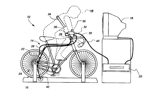
Fig. 1 is a schematic side view of one embodiment of the apparatus in
accordance with the invention utilized on a bicycle.
Fig. 2 is a block diagram of the apparatus in accordance with the invention
shown in Fig. 1.
Fig. 3 is a flow diagram of the video frame rate control program encoded on
the video disk in accordance with the present invention.
Fig. 4 is a flow diagram of the adjustment factor subroutine in accordance
with
the present invention.
Fig. 5 is an audio streaming control program flow diagram for audio data
chunks interleaved with video data chunks in accordance with the invention.
Fig. 6 is an audio streaming control program flow diagram for audio data
chunks in a file separate from the video data file.
Fig. 7A and 7B together is a logic flow diagram of the embedded processor in
the Interface Unit of the present invention.
CA 02267988 1999-04-06
WO 98I15112 PCT/US97/I7974
9
DETAILED DESCRIPTION OF THE INVENTION
Referring now to the drawing, a schematic side view of the apparatus in
accordance with a first embodiment of the apparatus 10 in accordance with the
invention is shown in Fig. 1. In Fig. 1, a user 12, shown in outline form,
operates an
exercise device 14 such as a bicycle which is mounted on a stationary exercise
stand
16. Positioned in front of the bicycle stand 16 is a television receiver 18
connected to
a game CD player 20.
The bicycle 12 is fitted with a cycle computer wheel pickup 22 which senses
the passage of a wheel magnet 24. The wheel pickup 22 is typically a reed
switch
which is connected to the cycle computer via leads 26. Leads 26 terminate at
contacts
(not shown) in a handlebar mount 28 fastened to the handlebar 30 of the
bicycle 14.
For use with the present invention, the cycle computer (not shown) is simply
removed
from the handlebar mount 28 and replaced with an interface unit 32 which clips
into
the handlebar mount 28. The interface unit 32 has contacts which mate with the
contacts connected to the leads 26 from the wheel pickup 22 mounted on one of
the
rear fork arms of the bicycle 14.
Optionally, the interface unit includes a heart rate receiver circuit therein
that
receives a radio frequency signal from a heart rate sensor/transmitter band
34. The
user 12 fastens the band 34 around his/her chest. A heart rate or pulse signal
is sent
normally from the band 34 to the user's receiver which may be a cycle computer
such
as a Vetta VHR-25 cyclocomputer. The cyclocomputer is usually mounted on the
bicycle handlebar. The transmitter band is close enough (within about three
feet) to
the receiver in the cyclocomputer to receive the weak signals transmitted. The
heart
rate receiver circuit in the interface unit 32 is located in the same place
and is
functionally the same as in the conventional cyclocomputer except that it
generates a
signal which is in turn fed to the CPU in the player 20 rather than a signal
that is
displayed on the handlebar mounted cyclocomputer.
The game CD player 20 is also connected to a remote game joystick controller
or keypad 36 which is removably fastened to the interface unit 32. The
interface unit
32 is electrically connected to the standard accessory input port on the
keypad 36 by a
CA 02267988 1999-04-06
WO 98I15112 PCTNS97117974
cable 38. The keypad is connected to the game CD player 20 by game cable 40.
The
game CD player 20 normally accepts several player keypads for additional users
to
play interactive games together by connecting one keypad to another keypad.
The
interface unit 32 utilizes this feature to connect the interface unit 32 into
the player
S central processing unit or CPU.
The exercise device. in this example, a stationary bicycle exercise stand 16,
includes a resistance means such as a variable friction resistance roller or
wheel 42.
This friction roller may be set by the user manually, or optionally may
include a
servomotor connected to the interface unit 32 via leads 46. In this latter
instance, the
10 user may control the resistance setting via the keypad 36 and/or the
resistance may be
controlled automatically through the player 20 by the program in accordance
with
another aspect of the invention as will be subsequently described.
In order to set up the apparatus 10 in accordance with this embodiment of the
invention, the user places the bicycle 14 on the stationary stand 16, hooks up
the game
player, such as a Panasonic REAL 3D0 Interactive Muitiplayer CD game console,
to
a TV or audio/video monitor 18 and connects the game player 20 to its remote
keypad v
36. The user then removes the cyclocamputer from the handlebar mount 28 and
replaces it with the interface unit 32, and connects the keypad 36 to this
interface unit
32 via connector cable 38 and optionally connects the resistance wheel 42 to
the
interface unit 32. Finally the user inserts a prerecorded video disc (CD) into
the
player, turns it on, starts the CD playing, and starts to ride, while watching
the TV
display.
The prerecorded video CD contains a control program in accordance with the
invention and a sequence of preferably real time video and audio frames
recorded
thereon such as a sequence from a single track trail ride in Moab, Utah, etc.
originally
made utilizing a helmet cam POV video camera. As the user pedals, he can
visually
see and hear the route along the single track. In addition, the control
program in
accordance with the invention modifies the video sequence rate in the player
20 CPU
fed to the TV 18 commensurately with the speed that the user 12 is pedaling.
This
gives the user/viewer a realistic feeling that he is actually following the
route of the
CA 02267988 1999-04-06
WO 98/15112 PCT/US97/17974
11
displayed single track in real time. In addition, the video sequence freezes
when the
user stops the bicycle, as would the scenery viewed on an actual ride.
The program may also change the resistance wheel 42 setting commensurate
with the terrain being traveled in the video. For example, the resistance may
be
increased when the video sequence involves uphill travel and decreased when
the
sequence shows downhill travel.
Fig. 2 is a block diagram of the apparatus in accordance with the invention
shown in Fig. 1. The apparatus 10 includes the interface unit 32 connected to
the
game controller or keypad 36 which is in turn connects to the CPU of the
player 20.
A prerecorded data storage medium 48, such as a compact laser disc (CD) in
accordance with the invention, is inserted into the player 20. This CD
contains media
- data including a set of digitized video frames and audio data packets and an
encoded
program which modifies the player control program 50.
T'he CPU of the player 20 includes the control program 50, a content buffer ~2
which decodes and decompresses the data stream read from the CD 48, a
dashboard
display overlay generator ~4. and a set of at least two display buffers ~6 and
~8. The
player 20 also optionally has inputs for signals from remote system CPUs 60.
The game player 20 includes a control program or operating system ~0 which
controls a11 basic input and display functions. Each CD typically played in
the
player 20 also includes a program which manipulates the control program ~0 to
produce the particular game scenery set and characters displayed and
manipulated on
the audio visual display 18.
However, in the present invention, instead of the game program on the CD, the
CD contains an exercise program thread to manipulate and display the real time
exercise inputs from the interface unit 32 such as speed, cadence, total
distance
traveled, lap distance, calories burned and time lapsed and time remaining in
the
particular exercise segment. These parameters are calculated and displayed on
a
"dashboard "overlay on the audio visual monitor 18. They are generated in the
overlay block 54 and fed to the display buffers 56 and ~8 as will be
subsequently
further discussed. The overall control of the video sequences, and the
start/stop of the
CA 02267988 1999-04-06
WO 98/15112 PCT/US97/17974
12
exercise overlay program is manipulated via the keypad 36 mounted on the
interface
unit 32 on the handlebar 30 of the bicycle 14.
The play of the video and audio sequences stored on the CD in accordance
with the present invention is controlled by the program shown in block diagram
form
in Fig. 3. This program is encoded on the CD and operates on the operating
control
program ~0 in the CPU of the player 20.
The present invention preferably utilizes real time video and audio recorded
sequences, such as can be recorded using a POV (Point of View) videotape
camera
mounted on an athlete's head or vehicle such as a bicycle. Each video frame
recorded
is assigned and has recorded with it a unique frame time stamp value and a
duration
stamp value for accessing the next frame packet of data upon playback.
Typically, in
real time recording, the duration stamp is a constant value. for example,
about 8
milliseconds. These frame stamp and duration values are necessary components
for
the playback apparatus to properly sequence and time the reproduced display.
The
1 ~ audio may be interlaced with the video or may be a separate track
recording. The
recorded sequence of video and audio are then digitized and recorded on a
video CD
along with the control program described below and shown in the Figures
herein.
The basic effect of the control program of the present invention is to control
the video frame reproduction rate in accordance with the exercise rate of the
user on
the exercise device 14. Therefore as the exercise rate increases, the frame
rate of
display increases, and the user sees the scenery flashing by faster. As the
exercise rate
decreases, the user sees the scenery pass by slower and slower, until the user
stops and
the scene displayed stops also. Thus the user gets the sensation of actually
traveling
through the scenery shown in the video.
The process flow begins, in Fig. 3, in operation 100 when the user inserts the
exercise video CD in the player 20, begins to play the CD, and begins pedaling
the
bicycle. First, the program sets, in operation 102, a cumulative time offset
(Tas) to the
current clock time of the CPU. This time offset tracks the total difference in
time that
the program modifies the video sequence due to the exercise rate of the user.
CA 02267988 1999-04-06
WO 98I15112 PCT/US97117974
13
The program next queries, in operation 104, whether a stop video stream flag
is set. This flag will be discussed further below in reference to the program
operations
in Fig. 4. However, if the Stop Video Flag is set, as when the user stops
pedaling to
rest for a period of time, control passes to a wait operation 106. Wait
operation 106 is
typically a process delay of on the order of 10 milliseconds, after which the
query in
operation 104 is performed again. If the Stop Video Stream flag is not set,
control
passes to operation 108.
In operation 108, the current frame time stamp value (Tf ) is retrieved and
the
current frame duration value (Td ) is retrieved from the decompressed stream
data in
content buffer ~2. Then the Adjustment value (Tad1) is obtained, in operation
110,
from the prograru sequence shown in Fig. 4. In operation 112, the variable
Tn~X, is set
equal to Tf + T~, + T~d~ + TpS. This is the clock time at which the next frame
should be
decompressed into the decompression buffer ~2.
In operation 114, the query is made whether current CPU clock time is equal
to or greater than T~~x,. In other words, whether it is time to show the next
video
frame. If the answer is no, control passes again to the wait operation 106. If
the
answer is yes, control passes to operation 116 where the next video frame is
decompressed to the decompression buffer in the control buffer block 52 of the
player
CPU. Control then passes to operation 1I8. In operation l I8, the contents of
the
decompression buffer are copied to either frame buffer A or frame buffer B,
whichever is pointed to by a pointer which alternates between the two frame
buffers.
As soon as the decompression buffer is copied to the pointed to frame buffer
in
operation 118,.control is passed to operation 120, where display objects such
as the
dashboard indicating the current heart rate, pulse icon and exercise status
parameters,
are overlaid into the buffer indicated by the pointer. Once the frame buffer
contents
are overlaid, control shifts to operation 122 and the contents of the frame
buffer
pointed to is sent to the video display or television set.
In operation 124, the frame buffer pointer is switched to the other buffer. In
operation 126, the contents of T~d~ are added to the Tas register so as to
keep track of
total adjustments to the sequence. Control then passes to operation 128 where
the
CA 02267988 1999-04-06
WO 98I15112 PCT/US97I17974
14
program queries whether there are any more video frames in the sequence on the
CD.
If there are none, the program ends in operation 130. If there are additional
frames,
control passes again to the wait operation 106 and the above steps are
repeated.
As can be seen by the above explanation, the video reproduction rate is
S modified by adding time or subtracting time from the prerecorded frame
duration
stamp value. In other words, the value of T~~t changes and thus modifies the
effect of
Td. Fig. 4 describes how T~~ is modified. The sequence of operations in Fig. 4
occur
continuously so as to always have a value of Tads corresponding to the user's
exercise
rate.
The sequence begins in operation I32 where the wheel speed input signal from
the wheel pickup is fed through the interface unit 32 into the CPU through the
game
controller keypad 36. The current speed, corresponding to miles per hour or
kilometers per hour, is obtained from the raw signal in operation 134. This
current
speed is continually updated so long as there is a wheel speed thread from the
I S interface unit 32. In addition, validity checks are performed in this
operation to
ensure that the signal is, in fact, a correct wheel speed signal.
Control then shifts to operation 136 where the query is made whether current
speed equals the last speed. If so, control returns to operation 132 for
another input
from wheel speed. If not, the query is made in operation 138 whether current
speed is
equal to zero. If not, control transfers to operation 140 where the query is
made
whether the Stop Video Flag is set. If this flag is not set, then control
passes to
operation 14Z where the video adjust factor, Tads is set to a table value
corresponding
to the current speed. An example of the table values is provided in Table 1
below.
These values are empirically determined to give the appearance to the user of
smooth
transitions between frames and may be different for different operating
systems and
different video player machine speeds. Table 1 values are chosen for video
operation
on a Panasonic 3D0 multiplayer system.
CA 02267988 1999-04-06
WO 98I15112 PCT/US97/17974
Miles per hour T~a~~s
2 112
4 96
6 80
8 72
10 64
12 48
14 36
16 28
18 20
12
22 8
24 4
26 2
28 0
3O -2
32 -4
Table 1
5 Control then shifts to operation 144 where Last Speed is set equal to New
Speed and control again transfers to operation 132 where another signal from
the
wheel sensor is awaited. If the Current Speed is equal to zero in operation
138,
control transfers to operation 146 where the Stop Video Stream flag is set and
current
clock time is saved. The Stop Video Stream flag is needed back in operation
104 to
10 cover the situation where the user stops to rest after beginning a
sequence. The
current clock time when this flag is set must be saved because, after the
start, in
operation 100, clock time is continuously running. Therefore, if the user
stops
momentarily, requiring the video sequence to freeze, the duration of the
stopped
period must be added to the time offset in order to keep the sequence
operating
I5 properly based on current clock time.
When the user again starts pedaling, a signal will be produced in operation
132. Control then sequences through operations 134 and 136 with "no" answers.
In
operation 140, the answer is "yes" to the query whether the Stop Video Flag is
set
Control then transfers to operation 148. Operation 148 resets the Stop Video
Flag and
20 adds to Tos the elapsed time between the current clock time at flag reset
and the clock
CA 02267988 1999-04-06
WO 98I15112 PC'T/US97/17974
16
time saved when the Stop Video Stream flag was previously set. This addition
to Tos
accounts for the lapse while the user was idle. Control then transfers again
to
operation 142 where the video adjust factor T~d~ is appropriately set as
described
above.
The sequence illustrated in Fig. 4 is continuous and proceeds whenever there
is a signal from the wheel speed monitor input thread from the interface unit
32.
Therefore this program sequence is constantly updating during the exercise
activity.
In contrast, the sequence illustrated in Fig. 3 operates only so long as there
are video
frames to be displayed. This is typically on the order of 20-30 minutes on
today's
game player systems.
Turning now to Figs. 5 and 6, flow diagrams for two versions of the audio
portion of the prerecorded sequence are shown. There are basically two ways in
which the audio data is encoded on the video compact disc. The audio data
chunks
may be in a separate file from the video file or the audio data chunks may be
interleaved with the video frame data chunks in the same file. The Fig. 6 flow
diagram is for processing audio data chunks which are stored in a separate
audio data
file on the CD. Fig. ~ provides a flow diagram for play of audio data chunks
which
are interleaved with the video frame data in the same file. Either case may be
used
dependent upon variables such as buffer space and storage medium drive speed.
The
audio program code is encoded on the CD as is the video program code described
above with reference to Figs. 3 and 4.
Referring now to Fig. 5, when the video stream starts, the audio stream starts
in operation 200. A digital pointer is set to one of at Ieast two audio
buffers in
operation 202 and control passes to operation 204 where an audio data chunk is
retrieved from the decompression content buffer 52. The audio data chunk is
then
loaded into the buffer pointed to by the audio pointer in operation 206. As
soon as
the audio chunk is loaded into this buffer, contents of the buffer begin to
play in
operation 2Z8. Meanwhile, operation control is passed to operation 210 where
the
query is made whether the audio stream is complete. If so, control passes to
operation
212 and the audio play stream stops. If the audio stream is not complete,
control
CA 02267988 1999-04-06
WO 98I15112 PCTIUS97I17974
17
passes to operation 214 where the pointer is shifted to the next buffer and
control is
passed back to operation 204. This process repeats until there are no more
audio data
chunks signifying that the audio stream is complete. In the case just
described, the
audio continues to play, even when the video slows in response to the actions
of the
user on the exercise device 14.
Referring now to the interleaved audio flow diagram in Fig. 6, when the first
video frame is decompressed and loaded into the display buffer as described
above
with reference to Figs. 3 and 4, the audio stream control begins in operation
220.
First, a pointer is set to one of at least two audio buffers in operation 22Z.
Control
then passes to operation 224 where an audio data chunk associated with the
current
video frame is retrieved from the decompression content buffer ~2. This data
chunk is
then loaded into the audio buffer pointed to in operation 226 and play of this
audio
chunk immediately begins in operation 228. At the same time, control shifts to
operation 230 where the stream is queried to determine if the audio stream is
complete. If not, the query is made, in operation 232, whether the next audio
data
chunk is available.
In other words, the query in operation 232 is whether the next video frame has
been called for display. This becomes important when the user is slowing down
the
video display by reducing his or her exercise rate, e.g. pedaling slower. If
the next
video flame has not been called, the next audio data chunk will not be
available. In
this case, operation 232 transfers control back to operation 228 and the
current audio
data chunk is replayed. Where the audio is wind noise, sounds of the road, or
natural
background noise in the country, the user will not likely be able to
distinguish that the
audio is being "looped back". Once the next video frame is called, the query
in
operation 232 will transfer control to operation 234 where the pointer is set
to another
buffer. Control then transfers back to operation 224 to get another audio data
chunk
and operations 226, 228, 230, and 232 are repeated until the last of the audio
stream is
processed. In this case, control is transferred to operation 236 where the
audio play is
stopped
CA 02267988 1999-04-06
WO 98I15112 PCT/US97/17974
18
If the user of the exercise device is maintaining a good speed, the need for
two
or more audio buffers becomes apparent. The audio buffers provide a smooth
sequencing of audio chunk play. In the present invention, the rate of audio
play
remains constant, independent of the video frame display rate so that the
audio pitch
and tempo remains constant and the user perceives a pleasing audio signal, as
he
would on location. Also, as the user slows down, the on-location sounds would
not
change appreciably. However, optionally, the audio volume may be made to
increase
or decrease as the user increases or decreases speed respectively. Therefore
looping
these audio chunks of wind and road noise back during slow exercise periods as
described in Fig. 6 maintains the perceptive effect of the audio being
independent of
the video rate of display, yet tying the audio content to the video frames
being
displayed. For example. in the case of a cross country trail bicycling video,
the
video scenes may show a very bumpy section followed by a smooth trail section.
If
the audio includes road noise rather than music etc., it would not be
realistic to have a
constant level of road noise. The audio stream during the bumpy section would
naturally have an increased level of road noise. Therefore the method of audio
control shown in Fig.6 is preferred, since the audio chunks are keyed to the
video
frames. Keeping this road noise level up as the bumpy video frames are shown
maintains the realistic perception of the journey. The loop back feature
between
operations 228, 230 and 232 is provided to maintain this consistency while
adjusting
the length of the audio stream.
The present invention is described above with reference to one particular
embodiment thereof. However, the apparatus and method of the invention may be
adapted to any video CD playing system. The particular embodiment above is
specifically designed for use in a Panasonic REAL 3D0 Interactive Multiplayer.
This game player can play audio CDs, video CDs, and game CDs which use the 3D0
operating system. Other operating systems and platforms may also be used,
including multimedia computers which accept video CDs. In addition, the
storage
medium may be other than a video CD. The storage medium may be a computer hard
disk or the video /audio file may be transmitted over cable, via modem, or
other
CA 02267988 1999-04-06
WO 98I15112 PCT/US97/17974
19
transmission means to the CPU of the playing device. Thus the playing device
may
be a multimedia PC, a dedicated video game player, or a multiplayer such as
the 3 DO
system or a set top box coupled via modem or cable to a television.
The primary difference between these various playing systems is that program
coding would change depending on the operating system used. However, the
program operations and steps described above remain the same and may be
implemented on any of these platforms. Other variations and modifications to
the
apparatus may also be made without departing from the scope of the invention.
For
example, the exercise device may be a stationary ski machine, stair stepper,
rowing
machine or treadmill. The interface unit may be permanently built in to the
control
system for the exercise machine or may be separately installed. The media
content
storage may be a video CD, a file transmitted via broadcast or modem, or other
digital
data storage device such as computer memory or computer hard drive. The player
CPU may be a commercial game player, a dedicated CPU made specifically for the
purpose of the exercise machine, or it may be included with an interface unit
integral
to a set top box connected to a TV.
Another variation, shown in Figs. 1 and 2, is the output connection of a
control
signal to the exercise device 14. The prerecorded video may include coded data
for
setting the exercise device to predetermined resistance values. In this case,
the
program would include a control thread which accesses the control data
associated
with the video frame which sets the resistance. This data would then be
translated
into setting values which would be transmitted to the servomotor or stepper
motor
connected to the resistance control such as resistance wheel 42 on the
exercise stand
16 shown in Fig. 1.
The interface unit 32 includes a battery, a PIC programmable processor, a
heart rate receiver tuned to the transmission frequency of the heart rate
transmitter 34,
a series of shift registers, a 10 MegaHertz clock, wheel speed input terminals
which
mate with the contacts on the cyclocomputer handlebar mount 28, and a nine pin
output connector which connects the interface unit 32 to the 3D0 game
controller
keypad 36. The PIC processor is an 8 bit device, which processes the incoming
tics,
CA 02267988 1999-04-06
WO 98/15112 PCT/IT597/17974
or beats from the wheel speed sensor and the ticks from the output of the
heart rate
receiver. The 3D0 multiplayer is a 32 bit device. The shift registers in the
interface
unit convert the data from the PIC Processor to 32 bit words for compatibility
of
communication with the 3D0 player. The interface unit 32 basically collects
data
5 from the heart rate and wheel speed inputs and transmits the heart rate and
wheel
speed data to the 3D player when queried by the main program in the 3D0
player.
Provision may also be included in the interface unit 32 for providing a signal
to a
stepper motor or servomotor on the exercise device to vary the resistance
provided by
the resistance roller 42.
10 A logic flow diagram of the embedded program in the PIC processor is shown
in Fig. 7. When the user turns on the 3D0 player and inserts and plays a video
CD,
the interface unit processor starts in operation 400. A run time crystal clock
RTCC is
used to run the processor and to measure time durations between input pulses
in the
PIC processor. This RTCC runs at 10 MHz and counts between zero and 255. The
1 ~ output rolls over at 25~. This equates to a rollover time of about a
maximum of 2
milliseconds. Operation 402 initializes several flags and registers to zero.
Specifically, a load pulse flag, a heart beat flag, a heart tic flag, a wheel
rotation flag
and a wheel tic flag are set to zero. Also, a heart count register, a heart
store register,
a wheel count register, and a wheel store register are set to zero. The heart
count
20 registers and wheel count registers are used to accumulate time tics
between input
pulses from the heart rate receiver and the wheel rotation reed switch as will
become
more apparent below.
Control then transfers to operation 404 where the run time crystal clock is
set
to 99. This clock then counts up to 255 and then rolls over to zero and
continues
counting to 255, rolling over, and repeating. This works out to about 2
milliseconds
between rollovers. Control then shifts to operation 406 where the query is
made
whether the RTCC has rolled over. The actual query is whether the RTCC is less
than
90. If yes, the RTCC is reset to 99 in operation 408 and the heart tic and
wheel tic
flags are set in operation 410. Control then proceeds to operation 412. If the
RTCC
has not yet rolled over, control passes directly to operation 4I2 without
passing
CA 02267988 1999-04-06
WO 98/15112 PCT/US97/17974
21
through operations 408 and 410. Operation 412 queries whether a load pulse
flag has
been set by the 3D0 control program. This flag will be set if the 3D0 program
is
ready to receive input from the interface unit 32. In this case, control
transfers to
operation 4l4 where the interface unit 32 output registers are loaded with the
contents
of the heart store and wheel store registers. These output registers are then
immediately read by the 3D0 operating system through the connection through
the
game controller or keypad 36.
Whether or not the load pulse flag is set by the 3D0 player, control then
passes to operation 416 where the query is made whether a heartbeat flag has
been set,
i.e. a beat has been received by the heart rate receiver. If a beat has been
received,
control passes to operation 418 where the heart count register contents are
transferred
to the heart store register. Then, in operation 420, the heart count register
is reset to
zero and the heart beat flag is reset in order to sense another heartbeat.
Control then
proceeds from operation 420 to operation 422. If no heartbeat has been
received in
the heart rate receiver, and thus the heart beat flag is not set, operation 4
i 6 transfers
directly to operation 42Z.
In operation 422 the query is made whether the wheel rotate flag has been set
by passage of the wheel magnet 24 past the reed switch 22. If not, control
passes to
operation 424. If the wheel rotate flag is set, control passes to operation
426 where
the contents of the wheel count register are moved to the wheel store
register. Control
then transfers to operation 428, where the wheel count register is set to zero
and the
wheel rotate flag is reset in order to sense receipt of another wheel
rotation.
Operation 4Z4 queries whether the heart tic flag is set. If so, control
transfers
to operation 432 where the heart count register is incremented and the heart
tic flag is
reset. Control then transfers to operation 430. If the heart tic flag is not
set,
operation 424 transfers control directly to operation 430.
Operation 430 queries whether the wheel tic flag is set. If so, control
transfers
to operation 434 where the wheel count register is incremented and the wheel
tic flag
is reset. Control then passes back to operation 406. If the wheel tic flag is
not set,
operation 430 passes directly back to operation 406.
CA 02267988 1999-04-06
WO 98I15112 PCT/US97/17974
22
The sequence of operations described in Fig. 7 is continuous. The net effect
of the sequence is to constantly update the heart count, wheel count, heart
store, and
wheel store registers as wheel rotations and heart beats are received. This
information
is passed into the output registers for transmission to the 3 DO control
system
whenever the 3D0 control program requests input which is about 60 times per
second.
It is to be understood that the above description is exemplary of one
embodiment
only.
Other programmed method variations and equivalents for providing the above
exercise device and user input to the playing device will become readily
apparent to
those skilled in the art. In addition, other playing devices may be utilized
in place of
the 3D0 system. For example, an MPEG-2 compatible player coupled to a personal
computer may be used, or another CD player using a different operating system
such
as a Sony video game CD player. In these cases, the hardware in the interface
unit
may have to be modified to achieve bit compatibility with the particular
player input
devices. However, the basic logic flow of the example described above could
still
apply.
While the present invention has been described above with reference to a
particular embodiment thereof, it is to be understood that many variations,
alterations
changes and additions may be made to the apparatus, system and method above
described. It is therefore contemplated that all such modifications,
alternatives and
variations are within the scope of the present invention as defined by the
following
claims. All patents, provisional patent applications, and printed publications
referred
to herein are hereby incorporated by reference in their entirety.