Note: Descriptions are shown in the official language in which they were submitted.
CA 02268071 1999-04-O1
WO 98110587 PCT/US97116486
MOVING PICTURE CAMERA WITH UNIVERSAL SERIAL BUS INTERFACE
S
Field of the Invention
The present invention relates to video. In particular, the present invention
pertains
to "plug and play" cameras that can be connected to, for example, a personal
computer
via a standard bus.
Background of the Invention
FIG 1 depicts a conventional video conferencing system 10. A camera 12 of the
video conferencing system 10 has a charge-coupled device or CCD 13 on which an
image
is incident. Cameras of the type illustrated in FIG 1 called ColorCam are
available from
Connectix~ a company located in Mountain 'View, California. The CCD 13 outputs
a
still or moving pictwe video signal representing the image or images incident
thereon to
an analog to digital converter (ADC) 15. The ADC 1 S illustratively outputs an
RGB
format digital video signal. The digital video signal is conveyed by a cable
16 to a
parallel printer port 18 of a computer system 20. The picture data received
from the
parallel printer port 18 is provided to a frame capture I/O expansion card 19
via a
proprietary internal cable 23. The I/O expansion card 19 has a buffer for
receiving frames
of the digital video signals for communication via I/O expansion bus 22 to an
I/O bridge
24. The I/O bridge 24 retransmits the video data thus received via a system
bus 26 to a
processor 28. Once at the processor 28, the bit rate of the video signal may
be adjusted
in a number of ways. Far instance, the resolution or frame rate may be
decreased.
Alternatively, the video may be encoded according to one of a number of
encoding
standards including ITU's (International Telecommunications Union) H.261,
H.262, or
CA 02268071 1999-04-O1
WO 98I10587 PCT/US97/16486
H.263, ISO/IEC's MPEG-1, MPEG-2, JPEG, or motion JPEG, etc. After reducing the
bit rate of the video signal sufficiently, the bit rate reduced video signal
may be outputted
from the processor 28, via system bus 26, I/O bridge 24 and I/O expansion bus
22 to a
modem 30. The modem 30 transmits the bit reduced video signal to a remote
video
conferencing system 10' via a network 32, such as a public telephone network,
local area
network (LAN), metropolitan area network (MAN), wide area network (WAN), etc.
The
bit rate reduced video signal is received at a like modem 30 and communicated
to a like
processor 28 where it is restored (decompressed, spatially and/or temporally
interpolated,
etc). The restored video signal is then outputted to a graphics adapter 33 and
displayed
on a display monitor 34. Alternatively, the restoration can be performed on
the graphics
adapter 33 using specialized hardware.
A conventional personal computer system 20 generally only has two standard
ports,
namely, a parallel port and a serial port. The parallel port is typically used
for outputting
data to a printer and can output data at a maximum i 00 Kbyte/sec burst
transfer rate using
a handshake protocol. The serial port, on the other hand, is typically
connected to an
input device, such as a mouse, or a modem and can typically only sustain a
115.2 Kbit/sec
transfer rate (e.g., using a 16550 UART). As noted above, the camera 12 can
connect to
a standardized connector at the printer port 18. This enables the camera 12 to
be used
with different platforms (e.g., different computer systems). However, to do
so, the printer
must be disconnected from the parallel port 18 as the parallel port 18 can
only support
data transfers between the computer system 20 and one other peripheral device
(pursuant
to its handshake protocol}. This is disadvantageous. Another disadvantage of
the
computer system 20 is that the computer system housing (represented by 21 )
must be
opened to install the frame capture I/O expansion card 19 and to manually
connected the
2
CA 02268071 1999-04-O1
WO 98I10587 PCT/US97/16486
proprietary connector 23 between the parallel port 18 and the frame capture
I/O expansion
card 19. Thus, a novice user may find it difficult to install and to configure
the camera
12. Moreover, for many systems 20, the walTanty on the computer is voided if
the
computer housing 21 is opened by the user.
The camera 12 is well suited for non-real-time still picture capture. In
capturing
a still image, there is no requirement to transfer the data of the still
picture from the
camera 12 to the computer system 20 (or to, for example, another video
conferencing
system 10') in real time. A raw RGB signal for a 600 x 800 pixel display
screen contains
(800 x 600 pixels) ~ 24 bits/pixel = 11,520,000 bits. At the maximum 100
Kbyte/sec burst
transfer rate of the parallel port 18, the transfer of one still image from
the camera 12 to
the computer system 20 takes over 14 seconds (without adding in the overhead
of the
printer port 18 handshake protocol or any other bus arbitration of transfer
latency of the
computer system 20). Moreover, to transfer such information via modem 30
connected
to an ordinary telephone network (which can have up to a 28.8 Kbitlsec
transfer rate)
1 S would require 400 sec. This presents a problem for real time video
communication, such
as, video conferencing, in which moving pictures must be captured,
transferred, and
displayed in real time.
It is possible to program processor 128 to perform a limited amount of real
time
video capture for transfer via the network 32 using the video conferencing
system 10.
The problem is that only a limited amount of data can be transferred from the
camera 12
via the printer port 18 to the frame capture I/O expansion card 19 due to the
limited
bandwidth of the printer port 18. As such, the resolution of the image must be
drastically
reduced to no larger than 128 x 96 pixels (for a black and white image) which
results in
approximately a 2" x 2" picture on a normal display monitor 34. The frame rate
is
3
CA 02268071 1999-04-O1
WO 98/10587 PCT/US97/16486
reduced to approximately 7 frames per second (using a frame dropping
technique). (Note
that ( 128 x 96) ~ (8 bits/pixel) ~ (7 frames/second) = 688, l28 bits/sec
which is slightly less
than the 100 kbyte sec maximum bust transfer rate of the parallel port 18.)
Moreover, the
image quality is severely deteriorated; ghost shadows are perceptibly present
in the
restored image, and the image breaks up whenever there is a large degree of
motion in the
picture.
FIG 2 shows a modified video conferencing system 50. In this system 50, the
camera 12 produces either an analog signal or a digital RGB signal carried by
cable 16.
The signal is received at a video processing I/O expansion card 52 that is
inserted into an
available slot 54 on the I/O expansion bus 22. The I/O expansion card 52 can
have a
frame capture circuit 55, an ADC 56 and a bit rate reduction circuit 58 (e.g.,
a video
compressor or frame rate/resolution reduction circuit). Examples of such
circuits include
the Vision Controller Processor (VCP~'~'') available from 8x8~'~"'', a company
located in
Santa Clara, California, and APV-3~ available from Lucent"", a company located
in
Murray Hill, New Jersey. The video signal is received at the video bit rate
reduction
circuit 58 on the video card 52 and is bit rate reduced thereat. The bit rate
reduced video
signal is then transmitted on the I/O expansion bus 22 to the processor 28
and/or to the
modem 30.
The video conferencing system 50 can provide an adequate frame rate and
resolution video signal at a bit rate which can be transmitted via the modem
30. The
problem with the system 50 is that the computer housing 60 must still be
opened to install
the video processing I/O expansion card 52. Second, the cable 16 connects to a
non
standardized connector 62 on the video processing I/O expansion card 52. This
reduces
the interchange-ability of video cameras 12 from platform to platform.
4
CA 02268071 1999-04-O1
WO 98/10587 PCT/US97/16486
FIG 3 shows an IEEE 1394 compliant camcorder 90 soon to be available from
Sony~'~"' a company located in Tokyo, Japan. The IEEE 1394 standard is a new
standard
for compression, storage and transfer of consumer and professional use digital
video
signals. The camcorder 90 includes a CCD 91, an ADC 92, a motion JPEG
compressor
93 and an IEEE 1394 interface 94. A video signal outputted from the CCD 91 is
converted to digital form in ADC 92 and then compressed in JPEG compressor 93.
The
compressed video signal is then formatted according to the IEEE 1394 standard
and
outputted to a bus using interface 94. The IEEE l394 bus is a 400 Mbit/sec bus
for
which no computer interface is yet available. Moreover, the IEEE 1394 bus is
designed
for transfer of video signals only--no specific provisions are provided for
supporting non-
video "bursty" data transfers.
Another problem specific to both the video conferencing system 10 and video
conferencing system SO pertains to properly setting up the system on each end
of the
communication. For instance, there is no guarantee that both the video
conferencing
system 10 and the video conferencing system 10' will use the same camera, the
same
frame captured board or technique, or have the same coding/decoding
capabilities. Even
when both video conferencing systems on each end of the communication are
identical,
a skilled operator is necessary to properly install the hardware and software
and also to
configure the software and hardware each session. In particular, the operator
must select
the correct software drivers, select compatible bit rate reduction
methodologies, i.e., the
correct encoding and decoding technique, options and parameters, the correct
resolution,
the correct frame rate, etc. In the case where each end of the communication
need not
have an identical video conferencing system 10 or 10' each operator must be
provided
with preliminary information on the capabilities of the system at the other
end and must
5
CA 02268071 1999-04-O1
WO 98I10587 PCT/US97116486
somehow agree to select the correct frame rate, resolution, encoding/decoding
technique
parameters and options. This makes it difficult for a novice user to establish
an
interactive video teleconference with an arbitrary user.
It is object of the present invention to overcome the disadvantages of the
conventional cameras. In particular, it is object to provide a video
conferencing system
in which the camera can be connected to a standard computer port without
opening the
computer housing, yet have sufficient resolution and fidelity to enable
interactive
communication of moving pictures. It is also an object to provide other kinds
of video
peripherals which can output and receive video signals in a simple "plug and
play"
fashion. It is furthermore an object to provide a video conferencing system
that can
arbitrate with a like far end video conferencing system and automatically
configure itself
on a session by session basis.
Summary of the Invention
These and other objects are achieved by the present invention. An illustrative
environment of use of the present invention is a video conferencing system
including a
first housing. A bus is contained in the first housing. A processor contained
in the first
housing is connected to the bus. A first interface is also contained in the
first housing and
connected to the bus. The first interface has a serial port that is accessible
externally to
the computer housing and to which a connection can be made externally with a
standard
connector.
According to one embodiment, a camera is provided that can be interconnected
to
the first interface, e.g., via a communications medium. The camera includes a
camera
housing. An imaging device, such as a CCD, tube, or CMOS photosensor, is
provided
6
CA 02268071 1999-04-O1
WO 98/10587 PCTIUS97/16486
inside the camera housing that converts moving pictures to a video signal. A
bit-rate
reduction circuit is also provided inside the camera housing and connected to
the imaging
device. The bit-rate reduction circuit reduces a bit rate of the moving
picture signal so
as to produce a bit-rate reduced video signal having a lower bandwidth than
the video
signal prior to bit rate reduction.
Illustratively, a second interface is provided inside the camera housing and
connected to the bit-rate reduction circuit. The second interface circuit
communicates the
bit-rate reduced video signal outside of the camera housing as a serial
bitstream to the first
interface via the communications medium. Illustratively, both the first and
second
interfaces are bidirectional. The first interface can download instructions to
the bit rate
reduction circuit via the second interface. Such instructions can include
instructions for
varying the bit-rate reduction by the bit-rate reduction circuit, e.g.,
resolutions and frame
rates, compression technique or various compression parameters.
According to another illustrative embodiment, the camera contains at least one
register or memory which contains information on the bit rate varying
capabilities of the
camera. Such information can be downloaded via the interfaces and
communications
medium to the processor in the first housing. The processor in the first
housing may
execute suitable software according to which the processor determines the
picture
resolution, frame rate, compression, etc. capabilities of its attached camera.
The processor
then may communicate with a like far end video conferencing system which also
possesses
information about the capabilities of its attached camera. Over the course of
the
communication, the two video conferencing systems negotiate acceptable bit
rate reduction
techniques (i.e., a compatible resolution, frame rate, compression technique,
compression
parameters, compression options, etc). In particular, the far end video
conferencing
7
CA 02268071 1999-04-O1
WO 98I10587 PCT/US97/16486
system transfers to the processor information regarding moving picture
restoration
capabilities at the far end. As a result of these negotiations, the processor
downloads
appropriate instructions to the second interface for varying the bit rate
reduction so as to
produce a bit rate reduced video signal that can be restored by the far end
video
conferencing system.
By reducing the bit rate of the video signal prior to transfer to the first
housing,
it is possible to input the video signal via a serial port and connector
already provided on
the computer for lower bandwidth data transfers. Thus, it is not necessary to
open the
first housing to install an interface card for receiving the video signal. On
the other hand,
the bandwidth of the video signal can be reduced in a controllable fashion,
e.g., by
resolution reduction, compression, or a combination thereof, to maintain
acceptable
fidelity.
Brief Description of the Drawing
FIG 1 shows a first conventional video conferencing system.
FIG 2 shows a second conventional video conferencing system.
FIG 3 shows a conventional camcorder.
FIG 4 shows a conventional Universal Serial Bus architecture.
FIG 5 shows a video conferencing system according to an embodiment of the
present invention.
FIG 6 shows a cellular telephone according to an embodiment of the present
invention.
FIG 7 shows a camcorder according to an embodiment of the present invention.
8
CA 02268071 1999-04-O1
WO 98/10587 PCT/US97/16486
Detailed Description of the Invention
According to the present invention, the bandwidth of the video signal produced
by
the camera is reduced so that the video signal can be inputted to an existing
serial port of
a computer system. The existing serial port has a connector that is external
to the
computer system and therefore the user need not open the computer system
housing to
install the camera. Thus, installation of the camera is simplified. Moreover,
many
manufacturers provide that the warranty on the computer is voided if the user
opens the
computer housing. As such, the invention also allows the user to circumvent a
potential
voiding of the computer system warranty.
In an illustrative environment of use, a camera is connected to a Universal
Serial
Bus (USB) interface. See Open HCI, Universal Serial Bus Specification v.1.0,
Jan. 19,
l996. USB is a bus and interface standard recently adopted by both computer
system
manufacturers and peripheral equipment manufacturers. FIG 4 shows a computer
system
with peripherals, such as a display monitor, keyboard, mouse, loudspeaker,
microphone,
telephone, etc., connected according to the USB architecture. Each peripheral
illustratively has a hub circuit 72 with one upstream port and one or more
downstream
ports. The upstream direction is towards the computer system 74. The
downstream
direction is away from the computer system 74. Peripherals can be connected in
any
arbitrary tree topology with the computer system 74 at the root.
Communication on the USB is via a serial bitstream in either an isochronous or
asynchronous fashion. Each hub therefore contains both transmit and receive
circuitry.
Communication can be achieved at a predefined "slow" rate of about 1.2
Mbits/sec or a
full rate of up to 12 Mbits/sec.
9
CA 02268071 1999-04-O1
WO 98/10587 PCT/US97116486
The USB standard, in addition to specifying a protocol for communication on
the
serial bus, also specifies a standard connector. The manufacturers which have
adopted the
USB standard will deliver future computers and peripherals with such standard
connectors
located externally to the housing of the computer systems and peripherals.
Thus, all
monitors, keyboards, microphones, etc, will be easily connected using standard
cabling.
Furthermore, USB provides a protocol for the computer 74 to recognize each
device
connected thereto. This simplifies installation of hardware components.
Devices
possessing such installation simplifications, i.e., simple connection and auto-
recognition
and configuration, are frequently said to be "plug and play."
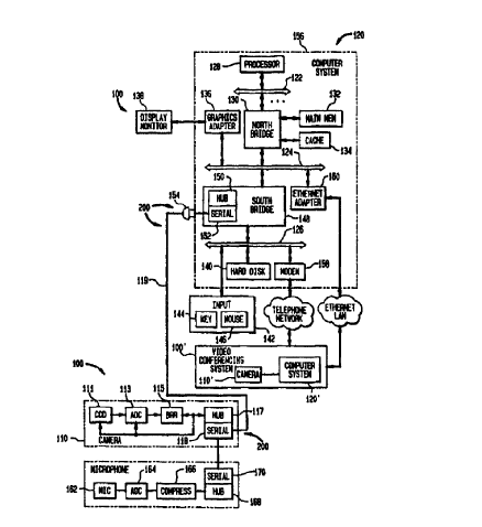
FIG 5 illustrates a video conferencing system 100 according to an embodiment
of
the present invention. As shown, a camera 110 is connected to a computer
system l20
externally to the housing 156 of the computer system 120. The computer system
120
illustratively includes a cpu bus 122, a system bus 124 (e.g., a PCI bus) and
an I/O
expansion bus 126 (e.g., as ISA bus). Connected to the cpu bus 122 is at least
one
processor 128 and a "north" bridge or memory controller 130. The north bridge
l30
connects a cache 132 and a main memory 134 to the processors 128 on the cpu
bus l22.
The north bridge 130 also enables data transfers between devices on the system
bus 124
and the memories 132 and l34 or the processors I28. Also connected to the
system bus
124 is a graphics adapter 136. A display monitor 138 may be connected to the
graphics
adapter 136. As shown, an Ethernet adapter 160 may be connected to the system
bus 124.
Connected to the I/O expansion bus 126 is a disk memory 140 and interface,
such
as an IDE interface, a modem 158, and input devices 142 such as keyboard 144
and
mouse 146. (Alternatively, the keyboard 144 and mouse 146 may also be
connected to
the USB hub 150.) Also connected between the system bus 124 and the I/O
expansion
CA 02268071 1999-04-O1
WO 98I10587 PCTIUS97/16486
bus 126 is a south bridge I48 or I/O bridge. The south bridge 148 enables data
transfers
between devices on the I/O expansion bus 126, such as modem 158, and devices
on the
USB 200 or devices on the system bus 124. Illustratively, according to the
invention, the
south bridge 148 also includes a USB hub 150. 'the USB hub 150 has one or more
serial
ports l52 that are connected to standard USB compliant connectors 154 to which
a
connection may be made totally externally to the housing l56 of the computer
system.
Illustratively, the USB hubs 150, 117, 168 and cables 119 form the USB bus
200.
Note that the south bridge 148 contains buffers for decoupling transfers
amongst
the system bus 124, I/O expansion bus 126 and hub 150. No "capture" or extra
buffering
capability is necessary to enable full rate data transfers on the USB 200 to
the hub l50.
The camera 110 is shown as including an imaging device, such as a tube, CMOS
photo sensor or CCD 111, on which video images are incident. The imaging
device 111
converts the image to a motion picture video signal representative thereof.
The video
signal is converted to digital form in ADC 113. The digital signal outputted
from ADC
113 is received at a bit rate reduction circuit 115. The bit-rate reduction
circuit 115 may
be a programmable frame rate/resolution reduction circuit. Advantageously,
however, the
bit rate reduction circuit is a programmable compressor. The bit rate reduced
video signal
is outputted to a USB hub circuit 117. The USB hub circuit 117 has a serial
port 118 that
can output the video signal as a serial bitstream via cable 119. The cable
119, which is
plugged into the connector 154 (externally to the computer housing 156),
delivers the
video signal to the serial port 152 of the hub circuit 150 in the south bridge
148.
The reduction of the bit rate by the bit rate reduction circuit 115 ensures
that the
video signal has a sufficiently low enough bandwidth to be received by the USB
serial
11
CA 02268071 1999-04-O1
WO 98I10587 PCT/US97/16486
port 152. Table 1 summarizes the average bit rates produced according to
several well
known standards:
TABLE 1
Standard Bit Rate
H.261 128 Kbits/sec
H.263 20 Kbits/sec
MPEG-1 1.55 Mbits/sec
MPEG-2 4-80 Mbits/sec.
For instance, as noted in Table 1, a fairly high quality interlaced video
signal can be
compressed to an average bit rate of 1.55 Mbits/sec using the MPEG-1 technique
or 4-80
Mbits/sec using the MPEG-2 technique. However, H.261, H.262 and H.263 can
compress
a video signal to even 15-20 kbits/sec with adequate quality for interactive
video
communication. On the other hand, the bit rate reduction circuit 115 may be a
less
sophisticated circuit which merely reduces the resolution and/or frame rate of
the video
signal. In such a case, the reduction in bit rate may be less, e.g., a
reduction to 4-8
Mbits/sec. If the bit rate is not sufficiently low enough to transfer the
video data via a
network, the processor 128 illustratively may be programmed with suitable
software for
compressing the bit rate reduced video according to the MPEG-1, MPEG-2, H.261,
H.262,
H.263, JPEG, motion JPEG, etc. compression standards. In such a case, however,
a
compressor preferably is provided in computer system 120 that is connected to
the system
bus 124.
As noted above, the USB 200 can be used to connect multiple peripherals in a
tree
topology. For instance, the peripherals such as the keyboard 144, mouse 146,
modem
158, microphone 162, etc. can also be connected to the USB 200. In such a
case, the data
12
CA 02268071 1999-04-O1
WO 98I10587 PCT/US97/16486
transfers to and from these additional peripherals are interspersed with each
other and with
the transfer of the video signal from the camera I 10. Several constraints
must be imposed
to enable both "bursty" data transfers to and from these other peripherals and
continuous
video signal transfers. First, the camera 110 should not obtain so much of the
bandwidth
of the USB 200 so as to "starve," i.e., prevent the other peripherals from
communicating.
Second, real time video requires continuity. To ensure continuity, a decoder
at the far or
receive end of the video signal must always have video signal data available
for decoding.
Simply stated, to avoid perceptible discontinuities or gaps in the video
signal, video signal
data must be delivered in a timely fashion. On the other hand, the video
signal takes a
certain amount of time to decode and display on the far or receive end (e.g.,
frames must
be displayed for a frame time). If too much video signal data is delivered at
one time,
a buffer overflow can occur at the receive end decoder. In order to
accommodate the
above constraints, the following guidelines are illustratively used:
(1) the USB 200 is operated at the full bit rate,
(2) the USB 200 is operated in isochronous communication mode, and
(3) an elaborate arbitration scheme is used to prevent peripheral
communication starvation and to ensure continuity of the video signal.
Generally speaking, the second guideline can be ensured by the first
guideline. The
second guideline allows for orderly scheduling of peripheral and video signal
data
transfers in achieving the third guideline.
Note that the USB 200, in particular, the serial ports 118 and 154 of the hubs
150,
117, 168 support bidirectional transfer of signals. To that end, the serial
port of each hub
I S0, 117, 168 has both transmit and receive circuitry. In addition to
transferring video
signals from the hub 117 to the hub l50, data rnay be transferred from the hub
150 to the
13
CA 02268071 1999-04-O1
WO 98/10587 PCT/US97/16486
hub 117 by interspersing the video signal and the data transfer signal. Such
data transfers
can be used to program/adjust the bit rate reduction circuit 115 (the ADC 113
and/or the
imaging device 111 ) to vary the bit rate reduction. Programmable compressors
115 are
available which include basic spatial and temporal compression sub-circuitry
and
processors, such as RGB to YLJV converters, discrete cosine transformers,
inverse discrete
cosine transformers, quantizers, dequantizers, variable length encoders, video
buffer
verifiers, motion estimators, motion compensators, block matchers, loop
filters, inter/intra
decision circuits, etc. Illustratively, such programmable processors can be
programmed
to compress the video in compliance with a number of compression standards
such as,
H.261, H.262, H.263, MPEG-1, MPEG-2, JPEG, motion JPEG, etc. Furthermore,
within
any given standard, different parameters may be adjusted such as quantization
step sizes,
inter/intra decision thresholds, group of picture formats, bit rate, etc and
different
compression options, such as anthmetic coding, may be selected.
Illustratively, the bit rate
reduction circuit l15 can be programmed by means of a transfer of data and/or
instructions via the USB 200. Even a simple resolution/frame rate reduction
circuit 115
has programmable parameters such as resolution, number of frames per second,
frame
dropping rate, etc. For example, the bit rate reduction circuit 115, ADC 113,
and/or
imaging device 111 can be programmed to drop a certain fraction of frames or
to change
the frame interval, e.g., to change the frame sampling time from 1/30th of a
second to say
1 /6th of a second. The latter frame integration technique tends to produce a
smoother
lower frame rate video signal than the frame dropping technique.
Illustratively, data may
be transferred via the USB 200 to the bit rate reduction circuit 115 or
imaging device 111
for varying the resolution, frame interval, frame dropping rate, etc.
14
CA 02268071 1999-04-O1
WO 98I10587 PCT/US97/16486
Note that at least the bit-rate reduction circuit l15 contains registers
and/or
memory in which information indicating the bit rate variation capabilities,
i.e.,
compression standards, adjustable compression parameters, selectible
compression options,
supported transfer bit rates, frame rates, resolutions, etc., may be stored.
Such information
may be prestored in a ROM or may be loaded into the bit rate reduction circuit
11 S on
power-up during an auto-configure procedure of driver software executed by the
processor
l28 for configuring the camera 110. The capability information can be
downloaded via
USB 200 to the processor 128 and/or transferred to a remote video conferencing
system
100' in the course of negotiating video conferencing terminal capabilities
(i.e., display
resolution, communications rate and parameters, bit rate reduction
capabilities, etc.) in
setting up of a communication. For example, when a user at the near end, local
video
conferencing system 100 (camera 110 and computer system 120) initiates a
communication with a far end, remote video conferencing system 100' (camera
110' and
computer system 120' ), the processor 128 at the near end, local video
conferencing system
1 S 100 obtains the capability information stored in the registers or memory
of the bit rate
reduction circuit 1l5 of the camera 110. To that end, the processor l28
transfers an
instruction requesting such information via cpu bus 122, north bridge 130,
system bus l24,
south bridge 148, hub 150, cable 119 and hub 117, to bit rate reduction
circuit 115. In
response, the bit rate reduction circuit 115 transfers such information to the
processor 128
via hub 117, cable 119, hub l50, south bridge 148, system bus 124, north
bridge 130 and
cpu bus 122. The processor 128 may select a subset of bit rate reduction
capabilities that
can be accommodated by the modem 130 or Ethernet adapter 160 (whichever is
used for
the communication). The processor 128 also determines the picture restoration
capabilities
of (i.e., decoding techniques, parameters and options, and temporal and
spatial
CA 02268071 1999-04-O1
WO 98/10587 PCT/US97/16486
interpolation capabilities supported by) the computer system 120. Information
regarding
the bit rate reduction and picture restoration capabilities at the near end,
local video
conferencing system l00 may be transferred to the far end, remote video
conferencing
system 100' . The far end, remote video conferencing system 100' also obtains
the bit rate
reduction and picture restoration capabilities of the camera 110 and monitor
13 8 thereat.
The near end, local video conferencing system 100 (camera 110 and computer
system 120)
and the far end, remote video conferencing system 100' (camera 100' and
computer
system 120' ) then negotiate which bit rate reduction methodologies to use. In
the course
of the negotiation, the video conferencing system at each end of the
communication can
transfer its bit rate reduction and picture restoration capabilities to the
other end in an
effort to determine a bit rate reduction and a picture restoration
methodology. When the
negotiation is complete, the processor 128 downloads instructions and
information to the
camera 110 for varying the bit rate reduction using a methodology for which
the far end,
remote video conferencing system l00' can restore the pictures as per
information
received from the far end, remote video conferencing system 100' regarding its
picture
restoration capabilities. Likewise, the processor 128 obtains the correct
information for
restoring received pictures that are bit-rate reduced by the far end, remote
video
conferencing system 100' as per information received from the far end
regarding its bit
rate reduction capabilities.
Advantageously, a microphone 162 receives an audible sound and converts it to
an audio signal in real time as the cameral 110 receives an image. An ADC 164
digitizes
the audio signal and an audio compressor 166 compresses the audio signal.
Illustratively,
a USB hub circuit 168 receives the compressed audio signal and transmits it in
bit serial
16
CA 02268071 1999-04-O1
WO 98I10587 PCT/US97/16486
form from serial port 170 to the hub 117, interspersed with the video signal
outputted
from the camera 110 and any other data signal transmitted on the USB 200.
The hub 1 SO receives the video (and illustratively the audio signal). The
received
signals may be transferred via south bridge 148, system bus 124, and north
bridge 130
into one of the memories 132 or 134. From there, the video andlor audio signal
may be
processed by the processor 128, e.g., error protected using an error
protection code,
compressed, if necessary, etc. The video and/or audio signal may then be
outputted (in
multiplexed form) via north bridge 130, system bus 124, Ethernet adapter 160
and an
ethernet network to the far end, remote video conferencing system I00' of
similar
architecture as the video conferencing system l00. Alternatively, or in
addition, the video
and/or audio signal can be outputted via north bridge l30, system bus 124,
south bridge
148, I/O expansion bus 126, modem 158 and a public telephone network to the
far end,
remote video conferencing system 100' . In another embodiment, the video
and/or audio
signal received at the hub 150 is outputted directly to the Ethernet adapter
160 or modem
I S 158, both of which can be connected to the USE 200.
A video and/or audio signal may be received from the far end, remote video
conferencing system 100' at the near end, local video conferencing system 100
shown in
FIG 5. The video and/or audio signal may be received at the ethernet adapter
160 or at
the modem l58. A video and/or audio signal received at the ethernet adapter
160 may
be transferred via system bus 124 and north bridge 130 to main memory 132 or
cache
memory 134. Alternatively, if the video and audio signal are received at the
modem 158,
the video and audio signal are transferred via the I/O expansion bus 126,
south bridge 148,
system bus 124 and north bridge 130 to the memory 132 or 134. From there, the
processor 128 may separate the video and audio signals for further processing
such as
17
CA 02268071 1999-04-O1
WO 98I10587 PCT/US97/16486
error correction, decryption, and restoration (i.e., decompressing,
spatial/temporal
interpolation, etc.). Alternatively, a special purpose processor (not shown)
may be
connected to the system bus 124 for performing at least the video signal
restoration. In
yet another embodiment, a special processor for performing video restoration
may be
included with the graphics adapter 136 to which the non-restored video signal
is directly
transferred (i.e., from the modem 158 or Ethernet adapter 160). The restored
video signal
is transferred to the graphics adapter 136 (or is present thereat). The
graphics adapter 136
outputs the restored video signal on the display monitor 138. In addition, the
restored
audio is also received via the graphics adapter 136 and outputted to a
loudspeaker
contained in the display monitor 138. Alternatively, an external loudspeaker
can be
connected to the USB 200. The audio signal can be restored by a number of
devices,
such as the processor 128. The restored audio signal is then outputted via the
USB 200
to the loudspeaker.
The system 100 according to the present invention achieves the following
1 S advantages:
( 1 ) Because the housing 156 need not be opened to install the camera 110,
the
user may install the camera 110 without voiding a manufacturer warranty
on the computer system 120.
(2) Because the housing 156 need not be opened to install the camera 110, a
novice user can easily install the camera 110 by simply plugging cable 119
into a standard connector l54. Using an auto-recognition process native
to the USB standard, the camera 110 is automatically recognized and
appropriate driver software for using the camera 110 can automatically be
selected.
18
CA 02268071 1999-04-O1
WO 98I10587 PCT/L1S97/16486
(3) The cost of the system l00 is reduced. This is because no video capture
board is needed to receive the video signal as is required in either the
system of FIGs 1 and 2.
(4) The camera 110 is connected to the computer by way of a standard
connector 154. The camera is therefore cross-platform compatible.
(5) In addition to receiving a video signal from the camera 110, instructions
and data can be transferred to the camera 1l0, e.g., for varying the
resolution and/or compression, using the same connecting USB 200.
(6) The USB 200 connecting the camera 1l0 to the computer system 120 is
shared by multiple devices. Thus, the video signal produced by the camera
110 may be received by any other peripherals connected to the USB 200
other than the computer system 120, such as a modem 158, ethernet
adapter 160, etc.
(7) By providing bit rate reduction circuitry 115, the camera 110 is provided
with registers and/or memory in which bit rate reduction capabilities of the
camera 110 may be stored. Thus, the processor 128 can easily determine
the capabilities of the video conferencing system 100 and transmit such
capabilities to the far end, remote video conferencing system 100' during
a negotiation process. As such, the camera 110 enables automatic setup
during each communication session.
In another embodiment, the camera 110 and display monitor 13 8 can be combined
into a single device. For instance, a display monitor 138 can be provided with
a camera
110 installed within the display monitor housing above the display monitor
screen.
Illustratively, the hub 117 of the camera is connected to a downstream serial
port of the
19
CA 02268071 1999-04-O1
WO 98I10587 PCT/US97/16486
display monitor hub. The display monitor hub is then connected to the hub 150.
Such
an arrangement facilitates video communication. In particular, a user facing
the display
screen of the display monitor at the near end, local video conferencing l00 of
a
communication can view a moving picture image captured by the far end, remote
video
conferencing system 100' and transmitted via a network for decoding and
display at the
near end, local video conferencing system 100. Simultaneously, the user's own
image is
captured, digitized and encoded at the near end, local video conferencing
system 100 for -
transmission to the far end, remote video conferencing system 100' where it is
decoded
and displayed at the far end, remote video conferencing system 100'. In short,
"face-to-
face" communication is facilitated between a user at a near end, local video
conferencing
system 100 and a user at the far end, remote video conferencing system 100'.
Such a display monitor feature can be incorporated into a common cellular
phone.
Many cellular telephones have data inputs that enable the cellular phone to
function as a
modem. Such a data input may potentially be replaced with a USB interface. FIG
6
depicts a cellular phone 300 according to the present invention equipped with
one or more
liquid crystal display monitors (LCDs) 310, 315 and camera 1I0. LCD monitor
310
displays a near end, local image captured by imaging device 111. LCD monitor
315
displays a far end remote image captured by a far end, remote camera (not
shown). The
LCD monitors 310 and 315 are connected to downstream serial ports of the hub
117 of
the camera 110. The hub 117 is also connected to the hub 330 of a telephone
circuit 320.
Illustratively, in the example shown in FIG 6, the bit rate reduction circuit
l15 is an
H.263 compliant compressor. Illustratively, the LCD monitor 310 is also
provided with
a decompressor circuit 312, such as the VCP~'~'' (A like decompressor may be
provided for
LCD 31 S). Note also that an additional serial port can be provided in either
the hub 117
CA 02268071 1999-04-O1
WO 98/10587 PCT/US97/16486
or the hub 330 for connection to a hub of a computer (e.g., the hub 150 of the
computer
l20 of FIG 5).
Illustratively, in the telephone 320, near end, local audio is received at
microphone
l62 which outputs an analog audio signal to ADC 164. ADC 164 outputs a digital
audio
signal to compressor 366. The compressor 366 can operate in at least two
modes. When
no video is simultaneously transmitted, the compressor 366 uses an ADPCM
compression
technique which produces a 16 Kbit/sec audio signal. When video is
simultaneously
transmitted, compressor 366 uses a different technique such as CCITT's G.723,
which
produces a 5.3 or 6.3 Kbidsec bit rate compressed audio signal.
The compressed audio signal is outputted to a multiplexer/demultiplexer 335
which
also receives the compressed video signal outputted from hub 330. The
multiplexer/demultiplexer 33S selectively multiplexes the compressed audio and
video
signals and outputs the multiplexed signal to transceiver 330. Transceiver 330
transmits
the multiplexed signal via a cellular network to the far end, remote video
conferencing
system. The transceiver 330 also receives a multiplexed signal from the far
end, remote
video conferencing system via the cellular network. The received signal is
demultiplexed
by multiplexer/demultiplexer 335 into its constituent compressed audio and
video signals.
The audio signal is decompressed (by an audio decompressor not shown) and
outputted
via loudspeaker 340. The compressed video is outputted via hub 330 and hub 117
for
decompression and display on LCD 315.
FIG 7 shows an embodiment of the invention for a camcorder 400.
Illustratively,
the camcorder 400 is equipped with an imaging device 410. Such a signal may be
recorded as an analog signal on a removable storage medium using a removable
media
recorder/player 4S0. The video signal produced by imaging device 410 or
removable
21
CA 02268071 1999-04-O1
WO 98/10587 PCT/US97/16486
media recorder/player 4S0 may be outputted via jack 460 and/or outputted to
ADC 420
where it is digitized. A compressor or other bit rate reduction circuit 430 is
also provided
for reducing the bit rate of the digital video signal. A USB hub circuit 117
is connected
to the bit rate reduction circuit 430. Thus, in addition to the usual
camcorder output 460,
which may be a composite analog video signal, a USB compliant connector 440 is
provided which outputs a serial bitstream containing the video signal as
produced by the
USB hub circuit 117. The USB hub circuit 117 bidirectional and can receive
information
and instructions as well as transmit video signals.
In short, a camera is disclosed including a bit-rate reduction circuit
connected to
the CCD imaging device. Since the bit rate reduction circuitry is external to
the computer
system housing, the video signal can be inputted via a standard serial port
having a
connector external to the computer system housing.
Finally, the above-discussion is intended to be merely illustrative of the
invention.
Numerous alternative embodiments may be devised by those having ordinary skill
in the
1 S art without departing from the spirit and scope of the following claims.
22