Note: Descriptions are shown in the official language in which they were submitted.
CA 02268268 1999-04-08
WO 98I15201 PCT/LTS97/18004
- 1 -
HOOK FASTENERS AND METHODS OF MANUFACTURE
Bac ground of the Invention
The invention relates to improved hook members for
s hook-and-loop fastening and methods of manufacturing hook
members.
In general, hook-and-loop fasteners comprise two
mating components: a hook member that has upstanding,
hook-type fastener elements, and a loop member that has a
io surface that provides fibers or fiber loops with which
the hook elements become engaged.
As used here, a "hook member" means a member
having fastener elements whose hooks extend substantially
in a given plane. When of molded form, the stems of
is these elements are significantly broader in the direction
of their plane of extent than in the thickness direction
at a right angle thereto.
Hook fasteners are often preferred over other
types of fasteners, for instance, those having mushroom-
20 like form, because hook fasteners can provide more secure
engagement with the loops, offer advantages in
manufacturing, etc.
Loop members for hook-and-loop fastening have been
comprised of knitted, woven, and non-woven textiles. A
2s common example of a non-woven textile is known by the
term "spun bonded." It is made by spinning fine
filaments of plastic resin, e.g., polypropylene, and
distributing them in superposed layers. The fibers are
bonded to each other in random orientations, with a fine,
30 low-lying, nappy layer of looped and arched fibers
' exposed at the surface of the fabric.
Because non-woven fabrics are inexpensive, they
are desired for use as the loop part of fasteners for low
cost items, particularly disposable products such as
3s diapers, surgical gowns, and sanitary napkins. It is
CA 02268268 1999-04-08
WO 98I15201 PCT/LTS97/18004
- 2 -
desirable to provide fastener members useful with very
low cost, low loft non-wovens and other low loft fabrics.
Summary of the Invention
One aspect of the invention relates to a fastener
member useful for separable engagement with surface
fibers of a low-loft, non-woven fabric or the like. The
fastener includes a base and multiple rows of molded
hook-form fastener elements extending from the base and
exposed for engagement with the fabric. Each of the hook
1o form fastener elements comprises a stem portion joined at
one end to the base and at least one fiber-engaging hook-
form portion joined at the opposite end of the stem
portion and having a free end. The hook-form fastener
elements lying substantially only in planes aligned with
respective rows. At least some of the fastener elements
include a fiber-engaging plate portion at the outermost
portion of the hook-form portion, which plate portion
lies generally parallel to the base. The plate portion
provides an overhanging portion in the direction
2o perpendicular to its row that can engage the surface
fibers of the fabric.
Certain implementations of this aspect of the
invention include one or more of the following features.
The fastener member, in certain implementations,
provides: a plate portion which has a thickness, in the
direction normal to the base, that is less than the
height, in the direction normal to the base, of the free
end of the hook portion; fastener elements formed of
thermoplastic resin, the stem portions of the elements
3o being molded integrally with the base, and the plate
portion comprising a post-formed structure formed from
the resin of the uppermost portion of the molded fastener
element; that substantially a11 the hook-form portions of
the fastener elements in a first row extend in one
CA 02268268 1999-04-08
WO 98/15201 PCT/US97/18004
- 3 -
direction along the row and substantially all the hook-
form portions of the fastener elements in a neighboring
- second row extend in the opposite direction; that
substantially a11 of the fastener elements include plate
s portions; that substantially a11 of the fastener elements
in the first row contain a plate portion while
substantially a11 of the elements in the neighboring
second row do not; a stem portion which has substantially
flat relatively broad sides, a cross-section of each stem
1o portion, taken parallel to the base at the mid-height
region of the stem, having a width in the direction of
the row and a thickness in the direction perpendicular to
the row, the width being about twice the thickness or
more; a stem in which the width of the stem tapers from
1s the base to the hook-form portion; a central axis of the
stem is inclined, in the direction of the respective row,
at a substantially acute angle relative to the base.
Another aspect of the invention relates to a
fastener member useful for separable engagement with
2o surface fibers of a low-loft, non-woven fabric or the
like. The fastener comprises a base and multiple rows
of molded fastener elements extending from the base.
Each fastener element comprises a stem portion joined at
one end to the base, the stem being inclined, at a
2s substantially acute angle relative to the base in the
direction of the respective row of the element, and lying
substantially only in planes aligned with its respective
row relative to the base, and a fiber-engaging plate
portion disposed at the opposite, outermost end of the
3o stem portion, the plate portion extending transversely to
the direction of the respective row to form an overhang
portion that can engage the surface fibers of the fabric.
Certain implementations of this aspect of the
- invention include one or more of the following features.
3s The fastener member, in certain implementations, provides
CA 02268268 1999-04-08
WO 98/15201 PCT/US97/18004
a cross-section of each stem portion, taken parallel to
the base, has a width in the direction of the row and a
thickness in the direction perpendicular to the row, the
width being substantially greater than the thickness;
s that substantially a11 of the fastener elements include
plate portions.
In accord with another implementation of the
invention, a closure is provided comprising a fastener
member as described above and a non-woven fabric engaged
1o therewith, the base of the fastener and the non-woven
fabric being under tension in opposite directions such
that the fastener elements are subjected to and resist
shear forces caused by the tension loading, the tension
acting in the direction of the thickness of the stem
is portion.
Another aspect of the invention relates to a
method for making fastener members comprising extruding
molten resin and applying the resin to a molding roller
having forming cavities around its perimeter. Pressure
2o is applied to the resin to cause the resin to fill the
cavities, thereby forming a fastener member preform, the
fastener member preform comprising a base and a
multiplicity of discrete fastener element preforms
integrally molded with and extending from the base at a
2s substantially acute angle, the fastener element preforms
aligned in at least one row comprising stem portions with
outermost ends lying over the base substantially only in
planes aligned with its row. Fastener member preforms
are stripped from the molding roller. The outermost
3o portions of at least some of the fastener element
preforms are flattened, thereby forming generally plate-
shaped portions disposed at the outermost ends and
generally parallel to the base and perpendicular to the
row.
CA 02268268 1999-04-08
WO 98/15201 PCT/US97/I8004
- 5 -
Certain implementations of this aspect of the
invention include one or more of the following features.
The method, in certain implementations, provides: the
flattening comprises heating the outermost ends of at
least some of the fastener element preforms to a
temperature that is near the melt temperature of the
resin and applying pressure to the outermost ends; the
heating and the applying pressure are performed in a
single step; the single step comprises passing the
1o fastener member preforms by a heated roller and pressing
at least some of the fastener element preforms against
the heated roller; the fastener member preforms are
formed and the outermost ends of at least some of the
preforms are flattened as part of a single, continuous
process; the outermost ends of at least some of the
fastener element preforms are flattened in a post-
processing operation; prior to the flattening,
differences in the heights of the fastener element
preforms are corrected to ensure generally uniform
2o height; the correcting comprises pressing a knock-down
roller against the outermost ends of the fastener element
preforms; that substantially a11 of the fastener elements
are flattened; that a product is formed by the method.
In another aspect of the invention, the outermost
portions of some fastener elements are farther away from
the base, as formed, than the outermost portion of at
least some other fastener elements. At least some of the
outermost portions farthest away from the base are then
flattened, forming generally plate-shaped portions
3o disposed at said outermost ends and generally parallel to
the base and perpendicular to the row,
In a preferred embodiment, stripping the preforms
from the molding roller causes the fastener members
extending in one direction to be deformed to be of
CA 02268268 1999-04-08
WO 98/15201 PCT/US97/18004
- 6 -
greater height than fastener members in another
direction.
Another aspect of the invention relates to a
method for improving the engageability of a hook-type
s fastener member with a non-woven loop-type fastener
member. The hook-type fastening member comprising a base
and a multiplicity of generally hook-shaped fastener
elements integrally molded with and extending from the
base in a given direction or in that direction and the
opposite direction and lying only in planes parallel with
the given direction and perpendicular to the base. The
method comprises flattening outermost ends of at least
some of the fastener elements to form generally plate-
form portions disposed at the distal ends and generally
is parallel to the base and perpendicular to the planes.
The new hook fastener members are well suited for
engagement with low loft non-woven loop members since the
outer plate portions of the fastener elements that
overhang the sides of the elements are able to slide
2o under and initially engage the surface fibers of the loop
member. This feature can improve the level of engagement
of the fastener, especially when the fastener elements
are subjected to shear forces acting sideways relative to
the direction of the plane of the hook elements. The
2s flat-top hook fastener elements, while providing the
secure engagement by the hooks, also can avoid skin
irritation since the area of contact between the skin and
the fastener elements is relatively large. This is of
particular value when a hook fastener comes in contact
3o with the skin of babies. Finally, these hook fasteners
can be manufactured using conventional hook-member
tooling with simple additional post-molding steps.
Other aspects of the invention concern a
disposable absorbent garment having first and second
3s opposed longitudinal end portions, and comprises an outer
CA 02268268 1999-04-08
WO 98I15201 PCT/US97118004
cover; a body-side liner; an absorbent core located
between the outer cover and the body-side liner; a loop
member operably associated with the garment; and a
fastener member operably associated with the garment for
s separable engagement with the loop member, the fastener
member comprising: a base; and multiple rows of molded
hook-form fastener elements extending from the base.
According to one aspect of the invention, the
fastener elements are exposed for engagement with the
io loop member, each of the hook-form fastener elements
comprising a stem portion joined at one end to the base
and at least one fiber-engaging hook-form portion joined
at the opposite end of the stem portion and having a free
end, the hook-form fastener elements lying substantially
1s only in planes aligned with respective rows. At least
some of the fastener elements include a ffiber-engaging
plate portion at the outer most portion of the hook-form
portion, the plate portion lying generally parallel to
the base, the plate portion providing an overhang portion
2o in the direction perpendicular to its row.
Certain implementations of this aspect of the
invention have one or more of the following features.
The plate portion has a thickness, in the
direction normal to the base, that is less than the
2s height, in the direction normal to the base, of the free
end of the hook portion. The stem portion has
substantially flat relatively broad sides, a cross-
section of each stem portion, taken parallel to the base
at the mid-height region of the stem, having a width in
3o the direction of the row, and a thickness in the
direction perpendicular to the row, the width being about
twice the thickness or more.
Certain advantageous implementations of this
T aspect of the invention have one or more of the following
3s features. The loop member comprises a nonwoven material.
CA 02268268 1999-04-08
PC~f~~ 9 ~ / 1 ~ 00~
~_ ~y ,. . ~ . _ ~ Q998
lPc; _i Sl .. ,.
The loop member is joined to the outer cover in the first
opposed longitudinal end section and the fastener member
is operably associated with the second opposed
longitudinal end section. Preferably, the garment has a
longitudinal axis and the fastener elements are oriented
parallel to the longitudinal axis of the garment.
According to another aspect of the invention
concerning the disposable absorbent garment, each of the
fastener elements comprise a stem portion joined at one
end to the base, the stem being inclined at a
substantially acute angle relative to the base, in the
direction of the respective row of the fastener element
and lying substantially only in planes aligned with its
respective row. At least some of the elements also
comprise a fiber-engaging plate portion disposed at the
opposite, outermost end of the stem portion, the plate
portion extending transversely to the direction of the
respective row to form an overhang portion.
In preferred embodiments of the aspect of the
invention, a cross-section of each stem portion, taken
parallel to the base, has a width in the direction of the
row and a thickness in the direction perpendicular to the
row, the width being substantially greater than the
thickness.
Certain advantageous implementation of both of
these aspects of the invention include that substantially
.- a11 of the fastener elements include plate portions.
Brief Description of the Drawings
Figs. 1 and 2 are side elevational and plan views,
respectively, showing one embodiment of a hook fastener
member.
Figs. la, lb, and lc are detailed side
elevational, end, and plan views, respectively, showing a
single fastener element of the fastener member in Fig. 1.
;.~., v , ~~EE i.
CA 02268268 1999-04-08
WO 98/1S201 PCT/US97/18004
_ g _
Fig. 3 is a schematic representation of an
assembly line in which fastener members as shown in Figs.
1 and 2 are applied to diapers; Fig. 3a is a blow-up of a
portion of Fig. 3 showing the orientation of the fastener
elements on the diaper; and Fig. 4 illustrates the
direction of stress applied to the fastener elements
during normal use.
Figs. 5 is a schematic "peer-through window" view
illustrating the engagement of a hook fastener element
to with a non-woven loop member while Figs. 5a, 5b, and Fig.
5c are sequential diagrams illustrating the engagement of
a hook fastener element with a loop of a non-woven
fabric .
Fig. 6 is a schematic representation of the
is manufacturing process used to make hook fastener members.
Figs. 6a, 6b, and 6c are side elevational views
showing fastener element preforms used to make hook
fastener members.
Figs. 7 and 8 are side elevational and plan views,
2o respectively, showing a second embodiment of a hook
fastener member.
Fig. 7a is a detailed side elevational view
showing a fastener element of the fastener member of Fig.
7.
25 Figs. 9 and 1o are side elevational and plan
views, respectively, showing a third embodiment of a hook
fastener member.
Fig. 9a is a detailed side elevational view
showing a fastener element of the fastener member of Fig.
30 10 .
Figs. 11 and 12 are side elevational and plan
views, respectively, of a fourth embodiment of a hook
fastener member.
CA 02268268 1999-04-08
WO 98/15201 PCT/US97118004
- 10 -
Embodiments
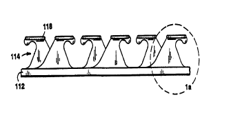
A preferred embodiment 110 of a hook fastener
member, particularly useful on disposable diapers, is
shown in Figs. 1, 1a, lb, lc, and 2. The hook fastener
member consists of a base sheet 112 and multiple parallel
rows of integrally molded hook-form fastener elements 114
extending from the base sheet. Although only three rows
are shown in several of the figures, it is to be
understood that the fastener member may comprise several
rows.
As shown in greater detail in Figs. la-lc, each
fastener element of Fig. 1 has a stem portion 116 of
uniform thickness that has flat vertical sides 116a, 116b
that extend normal to the plane of the base sheet 112.
Joined to the upper end of the stem is a re-entrant,
hook-form portion 117 that engages loops or fibers. At
the top of the fastener is joined a thin, generally disk-
shaped outer plate portion 118 oriented substantially
parallel to the base sheet.
2o The re-entrant hook-form portion curves over and
down toward the base sheet from the upper end of the stem
portion 116 to define a fiber-retaining recess 119 on the
underside of the hook-form portion.
The stem portion in side elevation, as seen in
Fig. la, tapers outwardly from a wide base to a
relatively narrow outer portion in the region of the
recess 119. The fastener elements are generally aligned
in multiple rows parallel with the flat sides of the
individual elements, and the outer plate portion of each
3o fastener element has portions that extend transversely,
to overhang the sides 116a, 116b of the fastener element
(Figs. lb, lc, 2).
In this preferred embodiment, the edge surfaces
123, 125 of the stem portion form angles 61 and 62
relative to the base sheet, respectively, that are
CA 02268268 1999-04-08
WO 98I15201 PCT/US97/18004
- 11 -
substantially greater than ninety degrees. Preferably,
61 and 62 are between about 30 and 160 degrees. More
preferably, they are each about 115 degrees and 125
degrees, respectively. Forming the stem portion such
s that the edges are straight or slant inward allows the
preform to be removed more easily from the molding roller
50 because the hook-form portion 117 can pass more easily
through the portion of the molding roller in which the
stem portion was formed.
1o For use in an important application for the new
fastener, in conjunction with non-woven loop members, the
fastener elements are generally quite small. Hence,
height 130 of the fastener element 114 is preferably
between about 0.005 inch and about 0.030 inch, with about
is 0.0l50 inch being most preferred. Furthermore, the base
width 126 -- i.e., the width of the stem portion, taken
parallel to the base sheet 112 at the level where the
stem portion joins the base sheet, disregarding the
fillets 128a and 128b -- is preferably between about
20 0.010 inch and about 0.025 inch, with about 0.017o inch
being most preferred.
Furthermore, the fastener elements are provided in
relatively high density, for example, from about 500 to
about 4,000, alternatively from about 1,000 to 2,500,
2s alternatively from about 1,500 to about 2,000 fastener
elements per square inch. For example, as shown in Fig.
2, the elements preferably are spaced apart laterally a
distance 135 of about 0.008 inch, and the stem portions
116 preferably have a thickness 136 of about 0.006 lineal
3o inch. This yields a widthwise density of approximately
71 fastener elements per inch. In the lengthwise
direction, there are preferably about 24 fastener
elements per lineal inch. Hence, there are preferably on
the order of l700 fastener elements per square inch in
3s this preferred embodiment.
CA 02268268 1999-04-08
WO 98/1520l PCT/US97/18004
- 12 -
A distinctive feature of the hook-form fastener
element 114 is the presence of the plate portion 118.
This feature contributes to making the hook fastener
embodiment 110 particularly useful for engaging the loops
s of non-woven fabrics in general and, in particular, the
low-loft non-woven fibers desired to be used on
disposable diapers.
As shown in Figs. 3 and 3a, disposable diapers 10
commonly are made on an assembly line with the fastener
1o tabs 12 extending to the sides, perpendicular to the
direction in which the diapers travel. The hook fastener
member is provided in large rolls 14 of hook fastener
tapes. As explained below, the hook fastener tapes are
made using a rotating molding roll in which the hook
1s elements are aligned with the circumference of the roll.
As a result of that process, the hook-form fastener
elements are aligned along the lengthwise direction of
the fastener tapes. For manufacturing efficiency, the
hook fastener tapes may be unwound and fed out running
2o parallel to the line of diapers. As each diaper passes
the appropriate station, a bonding apparatus 16 such as
an ultrasonic welder attaches a patch 18 of hook fastener
material to each of the fastener tabs 12. As a result,
the hook fastener elements are oriented parallel to the
25 longitudinal axis 20 of the diapers, as shown in greater
detail in Fig. 3a. Alternatively, the fastener tabs 12
having hook fastener material 18 attached thereto may be
formed in a separate process and the fastener tab
attached to the diaper during the diaper manufacturing
3o process. Such a separate process is described, for
example, in PCT Application Publication No. W095/05140
which is hereby incorporated by reference.
When the diaper is put on a baby, it will have the
configuration and orientation shown in Fig. 4. Hence,
ss when the fastener tabs 12 are engaged with the mating
CA 02268268 1999-04-08
WO 98I15201 PCT/US97118004
- 13 -
non-woven loop member strip 22, the tensile forces S
applied to the base of the fastener member and the loop
member will act perpendicular to the orientation of the
hook-form fastener elements, thereby subjecting the
closure to lateral shear forces, as suggested in Fig. 5.
During fastening the fastener tabs 12 will slide
slightly relative to the loop member strip 22. This is
indicated schematically in Fig. 5, which, with
exaggeration for purposes of illustration, shows the edge
of the fastener tab 12 at three successive locations 5a,
5b, and 5c. In Fig. 5 there is a "peer-through window"
depiction of a single fastener element 114 surrounded by
the surface fibers 23 of the non-woven loop member 22, as
seen from below the fastener element. As depicted in
i5 Figs. 5a, 5b, and 5c, which correspond in Fig. 5 to the
locations 5a, 5b, and 5c, respectively, as the fastener
element slides slightly, it is shown to intercept a
surface fiber 23 which is depicted as anchored to member
12. During the initial sliding action, an overhanging
2o portion of the thin outer plate 118 of the fastener
element slides under the low-lying surface fiber 23 (Fig.
5b), as an initial part of the engaging action. As
relative motion continues, the fiber is guided by the
fillets 120 between the plate portion 118 and the hook-
25 form portion 117 and the stem portion (see Fig. fib). The
fiber 23 is thus guided under the hook-form portion 117
and is secured in the re-entrant fiber-retaining recess
1l9 to more securely engage the fastener member with the
f fiber .
3o In Fig. 5b, the end of the hook element is shown
to have been deflected sideways by the force of
engagement with the loop member (shown exaggerated for
purposes of illustration). This bending, facilitated by
the relative thinness (dimension 136) of the element and
3s the off-center loading on the head of the fastener
CA 02268268 1999-04-08
WO 98/15201 PCT/US97/18004
- 14 -
element is seen to contribute to the effectiveness of the
engaging action.
As shown in Fig. 6, a preferred method for making
such flat-top hook fastener members entails extruding
s molten resin into the nip formed between a cooled molding
roller 50 and a pressure-applying roller 52, as taught by
Fischer, U.S. Patent No. 4,794,028, fully incorporated
herein by reference. The cooled molding roller has
cavities about its periphery that are configured to
io produce fastener element preforms 154, which are shown in
greater detail in Fig. 6a.
Because the fastener element preforms face in
opposite directions, the fastener element preforms in
half the columns are oriented along the direction of
15 travel of the tape, and the fastener element preforms in
the other half of the columns are oriented opposite to
the direction of travel of the tape. The fastener
element preforms that are oriented against the direction
of travel can leave the mold cavities of the moving roll
2o without significant bending, but the fastener element
preforms that are oriented along the direction of travel
are bent around the edges of the mold cavities as they
are extracted from the cavities. This deforms them
slightly, causing them to extend higher from the base
2s sheet and at a slightly steeper angle than the preforms
that are oriented along the direction of travel.
For making the two sets of preforms more uniform,
the preforms are passed under a knock-down roller 56, the
spacing of which, relative to wrap-around roller 57, is
3o adjustable. The knock-down roller pushes the higher and
steeper preforms back to the same level, relative to the
base sheet, as the level of the preforms that are
oriented with the direction of travel of the tape. This
leveling will permit more uniform formation of the plate
35 portions 118, discussed below. The knock-down roller 56
CA 02268268 1999-04-08
WO 98I15201 PCT/LTS97/18004
- 15 -
is located close to the position where the preforms are
withdrawn from the cavities so that the preforms are
still slightly soft and permanently deformable when they
pass under the knock-down roller and thus retain their
- 5 new shape.
Alternatively, to form the plate portion on only
some of the fastening elements preforms, the knock down
roller 56 can be removed. In this manner, the elements
oriented against the direction of travel are left in an
io elongated, higher state and may be deformed to form plate
portions 118 without forming plate portions on the
elements oriented along the direction of travel.
After the preforms have cooled sufficiently to be
strong enough to withstand pressure applied to them
15 without being deformed, the thin, outer plate portions
118 are formed, as at station 58. The plate portions can
be formed either in line with the molding process, i.e.,
as part of a continuous operation, or they can be formed
in a separate, post-forming operation at some later time.
2o Hence, the fastener tape is shown as broken in Fig. 6 to
indicate this variability.
To form the outer plate portions, the tape of
fastener element preforms is passed through gap 60
between a thermo-forming heated roller 62 and a support
25 roller 64, the gap width of which is adjustable. Roller
62 is heated to a selected temperature sufficient to
thermally reform the elements. Thus, as the preforms
come into contact with the heated thermo-forming roller
62, their outer ends 155 (Fig. 6a) are thermo-formed by
3o the action of the rollers to provide the disk-shaped
plate portions 118 of the fastener elements 114.
The selected temperature of roller 62 depends upon
the thermal properties of the particular resin being used
to make the fastener member and the selected speed of
35 operation. Presently, the shell material of disposable
CA 02268268 1999-04-08
WO 98I15201 PCT/I1S97/18004
- 16 -
diapers is often polypropylene. In certain applications,
nylon or other materials would also be appropriate. To
ensure good bonding when the hook fastener members are
attached to the fastener tabs of the diapers 12, the hook
s fastener member is also preferably made from
polypropylene. In this case, the roller 62 is heated to
a surface temperature of approximately 350~ Fahrenheit,
and has operated in a demonstration line at lineal speed
of approximately 11 feet per minute (Much higher speeds
io will be used in production.). The preforms approach the
roller 62 nearly tangentially. This results in a
temperature at the hook surface which is approximately
the same as the melt temperature of the polypropylene
resin, and causes the end of the preform to be softened
1s to the point of being permanently deformable under
pressure, without being caused to melt to a highly fluid
state.
It is, of course, foreseeable that other plastics
will be used to form such flat-top hook fastener members.
2o The material selected preferably has a relatively low
melt flow index, which is a measure of the viscosity of
the resin when it is molten. Resins with fractional melt
flow indices, i.e., indices that are less than 1.0, are
most preferred, although under certain circumstances and
25 hook designs, resins with melt flow indices as high as
5.0 or 10.0, or even higher, can be used by careful
balancing of the steps of the process. The temperature
of the roller 62 and the lineal speed through the station
58 are selected to impart a temperature to the hook
3o surface which renders the selected resin moldable. For
polypropylene, as noted above, it was found that 350~
Fahrenheit was appropriate. Further, additional support
rollers and the like may be employed to increase the arc
of the roller 62 which the preforms contact, thereby
3~ increasing the heating time for a given lineal speed.
CA 02268268 1999-04-08
WO 98115Z01 PCT/US97/18004
- 17 -
The width of the gap 60 between thermo-forming
roller and support roller 64 is adjusted to obtain the
appropriate height 130 (Fig. la) of the final fastener
elements, the height 130 in turn being a function of the
s height of the fastener element preforms. With regard to
the amount by which the tops of the hook elements are
thermoformed, and therefore with regard to the height 30,
it is important that the outer ends not be deformed so
much as to impair the geometry of hook-form portion 117
or the ability of the fastener element to engage and
retain the fibers of the loop member.
In general, the tops of the elements are
thermoformed by an amount to produce an effective
overhang of the plate portion, i.e., the amount by which
is the plate portion extends beyond (overhangs) either side
116a, 116b of the stem portion of the fastener element.
Depending upon the conditions of use, it is advantageous
for the amount of overhang to fall within the range of 5
to 50% of the thickness of the hook element; in other
2o conditions with the range of 10 to 30%; and in other
conditions, within the range of 15 to 25%. In certain
preferred instances, the overhang is about 25% of the
thickness of the stem portion. Thus, in preferred cases
the widthwise dimension 138 of the plate portions (Fig.
25 2) is approximately 1.5 to 2.o times the thickness 136 of
the stem portion and the vertical thickness 139 of the
plate portion 118 is between about 0.2 and 0.4 times the
thickness 136 of the stem portion. The lengthwise
dimension of the plate portion, in general, will be
3o somewhat longer than the widthwise dimension, and it is
generally allowed to be whatever dimension results from
thermoforming the plate portion sufficiently to obtain
the desired effective sideways overhang and hook height.
The thickness of one plate was 0.002 inch and the
35 overhang was 0.003-0.004 inch. A preferred thickness
CA 02268268 1999-04-08
WO 98/15201 PCT/US97/18004
- 18 -
range is 0.0001 to 0.005 inch, and in certain instances a
more preferred range is 0.001 to 0.004 inch.
Finally with regard to the manufacturing process,
in order for the plate portions 118 to be substantially
parallel to the base of the hook fastener member, it is
preferred that the heated roller 62 and support roller 64
rotate at speeds such that their tangential surface
velocities substantially match the feed rate of the
fastener tape. Otherwise, the plate portions will be
1o dragged by, or will drag along, the heated roller and be
deformed.
Another preferred embodiment 210 of a flat-top
hook fastening member is shown in Figs. 7, 7a, and 8.
This embodiment has a base sheet 212 from which extend a
multiplicity of discrete, flat-top fastener elements 214.
Each fastener element 214 has a canted stem portion 216,
having flat sides similar to sides 116a, 116b of Fig. lb.
These portions are integrally molded with and extend from
the base sheet. Each fastener element also has a
2o generally planar, disk-shaped outer plate portion 218
located at the outer end 220 of the stem portion that
overhangs the flat sides of the canted stem and a re-
entrant hook-form portion 217 depending from the outer
plate portion. The plate portion 218 extends generally
parallel to the base sheet 212.
As shown in greater detail in Fig. 7a, the general
configuration of the stem portion 216 of the fastener
elements can be characterized by two parameters. First,
it is canted relative to the base 212 in that the surface
222 of the stem portion on the side on which the hook
recess is formed forms an acute cant angle a relative to
the base. Preferably, cant angle a is between about 30
degrees and about 80 degrees; more preferably, a is
between about 40 and 60 degrees, and most preferably, a
is about 45 degrees.
CA 02268268 1999-04-08
WO 98I15201 PCT/I1S97/18004
- 19 -
The second parameter to characterize the
configuration of the stem portion is the base width 226
which, as before, is the width of the stem portion, taken
parallel to the base sheet 2l2 where the stem portion
joins the base, disregarding the fillets 228a and 228b.
Preferably, the base width is between about 0.0l0 inch
and about 0.018 inch; more preferably, the base width is
about 0.014 inch.
Finally, other parameters that characterize the
1o entire fastener element 214 are the height 230 of the
fastener element, as measured from the top surface of the
base sheet 212 to the top surface of the plate portion
218, and the widthwise dimension 238 of the plate
portion. The thickness of the stem portion 236 is
preferably the same as for the first embodiment, e.g.,
about 0.006 inch. Preferably, the height is between
about 0.005 inch and about 0.030 inch; more preferably,
the height is about 0.015 inch.
As shown in Figs. 7 and 8, the fastener elements
214 are arranged on the base sheet 212 with the fastener
elements in one column all canted in one direction and
the fastener elements in the adjacent column all canted
in the opposite direction. The spacing and density of
the fastener elements is approximately the same as the
spacing and density described above with respect to the
first embodiment.
The embodiment of the flat-top hook fastener
member of Figs. 7 and 8 is also made by the process shown
in Fig. 6. The hook preforms 254 are configured as shown
3o in Fig. 6b which, like the preforms 154 shown in Fig. 6a,
are generally of hook shape, although canted relative to
the base. Other profiles for a canted hook preform 254
can also be used. See, for example, Fig. 22 of Provost
et al., U.S. Patent No. 4,984,339, which is incorporated
by reference.
CA 02268268 1999-04-08
WO 98I15201 PCT/US97/18004
- 20 -
The canted relationship of fasteners elements of
Figs. 7 and 9 provide a longer fastener element and a
greater degree of off-center loading when subjected to
conditions as depicted in Fig. 4 of the preceding
embodiment. As a result, under loading conditions
depicted in Fig. 4, a greater degree of elastic
deflection of the hook end can occur that can increase
the fiber-engaging effectiveness of the hook elements.
A third preferred embodiment 310 of a flat-top
1o hook fastener member is shown in Figs. 9, 9a, and 10.
This embodiment is similar to the second embodiment 210
discussed above, the outer plate overhanging the flat
sides of the canted stem. The primary difference in this
embodiment is that the intersection of the canted stem
and the outer plate 318 defines a fiber-engaging hook
that is not re-entrant. This enables the overhanging
plate portion 318 to slide under loop members with
extremely low-lying loft. The third embodiment is also
manufactured by the method shown in Fig. 6, this time
2o using simple tapered fastener element preforms 354
without re-entrant hooks, as shown in Fig. 6c.
As described above, when the fastener element
performs face in opposite directions, the fastener
element preforms that are oriented along the direction of
travel are bent around the edges of the mold cavities as
they are extracted. This causes these preforms to extend
higher from the base sheet and at a slightly steeper
angle than the preforms that are oriented along the
direction of travel.
3o In certain instances is desirable to form the
outer plate portions 118 on only some of the fastener
element preforms. This can be achieved, for example, by
not passing the fastener element preforms under the
knock-down roller 56. Thus, since the fastener element
preforms have different heights from the base sheet,
CA 02268268 1999-04-08
WO 98I15201 PCT/US97/i8004
- 21 -
passing the fastener element preforms through gap 60
between the heated roller 62 and support roller 64 will
form the disk-shaped plate portions 118 on only those
fastener element prefvrms which extend furthest from the
base sheet (those preforms that are oriented along the
direction of travel) as shown in Figs. 11 and 12: For
some applications, having some of the fastener element
preforms possess the disk-shaped plate portions l18 and
others not possess the plate portions provides for a more
1o satisfactory balance of fastening properties (such as a
desired balance of peel and shear properties). In other
embodiments the fastener element preforms are formed to
have different heights from the base sheet independent of
their orientation during manufacture. This is
is accomplished through the use of mold cavities having
different depths during formation of the preforms. With
such preforms, in one embodiment flat tops are provided
only on those preforms having the greatest height.
Forming the fastener element preforms to have different
2o heights from the base sheet in some instance allows
greater control over the percentage of elements that are
"flat topped." It is possible to form fastener element
preforms with two, three or more different heights from
the base sheet.
2s Other embodiments are within the scope of the
following claims.