Note: Descriptions are shown in the official language in which they were submitted.
28/03 ' 99 15: 57 FA7C +49 89 9280,5444_ BARDEHL.E OFFICE MLTNICH f~ 010
4 r .. "-"' , _, .
~,T T (~,~ w 5 ~.a ~ I a i~J
PCT/EP97/05658 November 17, 1998
Erw~n Junker Maschinenfabrik GmbH
J 24437PC Ro/bb
Device for loading and unloading machine tools
The invention relates to 'a device for loading
and unloading machine tools.
Hitherto, it has been kriown to use immobile
loading and unloading devices, a.g. gantry loading
systems/robots or special loading systems which are
specifically designed for one machine tool or one
l0 machining operation. This is particularly complex and
expensive when the machining timds for workpieces lie
iz~ a range which means that. a separate loading unit for
the workpitsce is not loaded to its full capacity.
LJS-A-5, 364, 21.9 describes a, device which is used
Z5 in clean room or vacuum techniques in the production of
semiconductors. In this case, a i:irst vacuum chamber,
which is accommodated in a treatment unit, is coupled
to a second vacuum chambex, which is accommodated in a
movable case . After they have beeiz coupled together, a
20 loc3~c produces a connection betyeen the two vacuum
chambers. The case can be moved on rails inside a clean
room. The aim is to operate a v~icuum chamber without
surrounding air being able to , penetrate into the
vacuum. For this purpose, it is, absolutely necessary
25 for the vacuum chambers to be sealed with respect to
the ambient air.
EP-A-473,910 discloses a device for loading and
unload~.rig machine tools, in which ,device a loading unit
which aan be moved on rollers ovey a factory shop floor
30 can be coupled to and decoupled from a machine tool by
at least one fixing device. rn t~iis case, one part of
the fixing device is arranged on the machine tool and
another part, which interacts therewith, is arranged on
the loading unit.
35 The invent~.on is based on the object of
designing a device for loading amd unloading machine
AMENDEIa SHEET
CA 02268824 1999-04-15
26/05 '99 15:57 FAX +49 89 92805444 BARDEHLE OFFICE MUNICH C~ 011
- la -
tools in such a way that trlze ~.dEVice can be used
efficiently.
AMENDED SHEET
CA 02268824 1999-04-15
28/05 '99 15:55 FAg +49 89 92805444 BARDEHLE OFFICE MUNICH f~ 005
. ~ z
,J 24437-PC
Device fvr loading and unloading machine t~s
The invention relates to a device for loading
and unloading machine tools.
Hitherto, it has been known to use immobile
loading and unloading devices, ~e gantry loading
systems/robots or special loadi systems which are
specifically designed for one machine tool or one
1.o machining operation. This is art.icularly complex and
expensive when the machini times for workpieces lie
in a range which means th a separate loading unit for
the worlcpiece is not to ed to its full capacity.
Us-A-5,3s4,2i9 describes adevice which is used
in clean room or va um techniques; in the production of
semiconductors. r this case, a i:°irst vacuum chamber,
which is accomm aced in a treatment unit, is coupled
to a second v uum chamber, which is accommodated i.n a
movable case After they have beeiz coupled together, a
zo lock prod es a connection between th.e two vacuum
chambers. The case can be moved on rails inside a clean
room. a aim is to operate a vcicuum chamber without
surro ding air being able to ; penetrate into the
vac m. For this purpose, it is. absolutely necessary
fo the vacuum chambers to be sealed with respect to
a ambient air.
The invention is based on the object of
des~. n' ' ..,~--~f~~-~~~~g--~. oa a
tools in such a way that the device can be used
This object is achieved by means of the
features specified in claim 1.
According to the inventic5n, the loading unit
may also be used for a plurali~:y of machine tools,
since the fixing device allows th-e loading unit to be
coupled to any desired machine tool. The workpieces can
thus be transported to various machine tools. This is
advantageous in particular if ~rorlcpieces are only
partially machined on one mach;_ne tool. A further
CA 02268824 1999-04-15
26/05 '99 15:55 FAX +49 89 92805444 _, BARDEHLE OFFICE MUNICH C~J004
- 2~-
advantage is that when high numbErs of workpieces are
being machined, the machine fool caxl be loaded
automatically, without ruling out': the possibility of
loading the machine with ind~.vidu~il workpieces by hand
arid, in this period, using the, loading unit at a
different machine.
The subclaims relate to advantageous further
embodiments of the device describer~ in claim 1.
The invention ~.s explaineC3' in more detail below
7.0 with reference to exemplary embodiments illustrated in
the drawing, in which:
Fig. 1 shows a side view of the ,loadi.ng and unloading
device in a decoupled po;aition in front of a
z5 machine tool;
Fig. 2 shows a side view of the ;loading and unloading
device after it has been r,~ised;
20 Fig. 3 shows a side view of the loading and unloading
device after it has been Coupled to the machine
tool;
Fig. 4 shows a side view of the loading and unloading
25 device in another embod~.merzt ;
Fig. 5 diagrammatically shows r.ow the loading and
unloading device is used at a plurality of
machines.
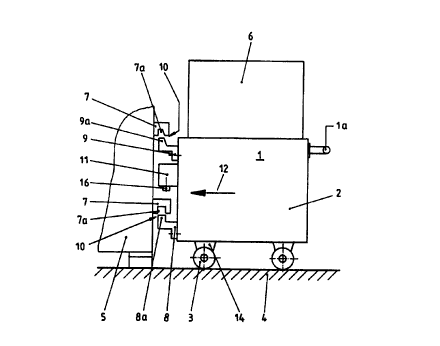
In accordance with Fig. 1,, the loading unit 1
is designed as an independent loaning system and can be
coupled to various machine tools. These machine tools s
are able to fulfill identical o~: different machining
operations.
The loading unit 1 comprises a basic frame 2,
which is transported on rollers 3, over the factory
shop floor ~, to a machine tool a. The loading unit 1
may be transported to the zndiv~:dual machine tools 5
CA 02268824 1999-04-15
28/0 '99 15:56 FAX +49 89 92805444 BARDEHLE OFFICE MLTNICH l~ 005
- 3 -
manually using a~ handle 7.a or is: designed as a floor
conveyox' vehicle. A loading device: 6 is mounted on the
basic frame 2.
zn the front area of the machine tool 5, there
are fixing pieces 7 to which the loading unit 1 can be
securely fixed. rrlating pieces 8, 9 are mounted on the
basic fx-ame 2 of the loading unit ~.. Together with the
mating piece s or 9, a fixing piece 7 forms a fixing
device 7Ø The fixing pieces ~ Dave slots 7a at the
bottom for the insertion of an up~~ardly directed web Sa
or 9a on the mating piece 8 or 9, respectively. The
mating piece 9 is designed as a faxed bearing unit, and
the mating piece 8 is designed ~s a movable bearing
unit.
To clamp the loading ur~i.t 1 in the f fixing
devices 10, a clamping unit 11 which is attackmd to the
loading unit 1 is provided.
zn Fig_ 1, the arrow 7.2 indicates how the
loading unit 1 is pushed in front: of the machine tool
5.
Fig. 2 illustrates how tile loading unit 1 is
raised vertically in the direction of the arrow 15 by
vertically extending the roller bearings 14 in the
direction of the arrow 13.
After the loading unit, 1 has been raised
vertically suff~.ciently far for the fixing devices 10
to close in a form-fitting manner, the loading unit can
be securely fixed to the machine fool. This is shown in
Fig. 3. zt can be seen from this figure that the
clamping unit 17. sexves to couple the loading ur~.it 7. to
the machine tool 5 in a fixed position. The clamping
unit 11 has a clamping element 16 which can be
extended, for example in the direc~tlon Qf the arrow 17,
and supports itself on the top: side of the bottom
fixing piece 7. After the loadixxg-unit 1 has been fixed
in the coupled position, the roller bearings 14 are
lifted off the factory shop floor:4 in the direction of
the arrow 14a, so that the entire loading unit 7. is
then suspended only from the machi;zie tool 5.
CA 02268824 1999-04-15
28/05 '99 15:58 FAg +49 89 92805444 BARDEHLE OFFICE MLTNICH f~ 008
_ _ 4 _
The loading unit 1 is released from the machine
tool 5 in the reverse order.
Fig- 4 shows a further embodiment for fixing
the loading unit 1 to a machi~~ze tool 5. In this
embodiment, the procedure may be similar to that for
the system in accordance With Fig~~. 1 to 3. The fixing
devices 1o in this case comprise fixing pieces 26 which
are attached to the machine tool 5 and have upwardly
directed slots 26a, which inteo,act with downwardly
directed webs 25a on mating F,ieces 25 which are
attached to the loading unit 1. AEtex the loading unit
has been raised in the direction of the arrow 27 by
extending the roller bearings 1~~, the webs 25a are
positioned above the slots 26a anc~, by the loading unit
1 being lowered, the webs 25a comE into engagement with
the slots 26a. As soon as this hay taken place, ~-n this
case too it ~.s possible, by retracting the roller
bearings 14, to ensure that, thba loading unit 1 is
suspended from the machine tool 5.. In this case, it is
possible to dispense with a cl~~mping unit ZZ , as
illustrated in Figs_ 1 to 3, sinc,> the system is fixed
securely merely by the weight of t_ne loading unit 1.
Fig. 5 shows how the load~:ng unit 1 is used for
a plural ity of machine tool s 2 0 , 2:~. , 22 _
rn the ppsition illustrated, the loading unit 1
is mounted on the machine 21 and this machine can be
J.oaded and unloaded. ~t is now po Bible either for the
loading unit 1 simply to load and unload the machine
21, or, after machining has t<.~ken pJ.ace, for the
finished workpiece to be placed on an intermediate
repository which is mounted on tY~e loading unit 1 and
for the entire loadzng unit to be moved to the mach~.ne
20 or 22 either by the machine operator or as a floor
conveyor vehicle.
In this way, it is possavble, for example, to
achieve a production system in avhich a plurality of
machine tools cax~ be loaded and ur~loaded using a single
loading unit 1. zn the manufacturing route, it is
possible to provide a cell solution for a plurality of
CA 02268824 1999-04-15
28/03 '99 __-15:58 FAR +49 89 9280.5444 BARDEHLE OFFICE MUNICH ~J007
- 5 -
machine tools, with a single, cast-effective loading
unit 2 being used for loading a:~d unloading all the
machine tQOls. The manufacturing :cell also includes a
location for storage magazines, for blanks 23 and
finished parts 24.
an alternative to the loading unit, it is
als4 possible to couple a unit which has a different
task to the machine. In this case, instead of the
loading device 6 a unit with a ~~iffexent function is
mounted on the same basic frame 2.:,
CA 02268824 1999-04-15