Note: Descriptions are shown in the official language in which they were submitted.
CA 02269064 1999-04-16
WO 98116174 PCT/US97117927
-I-
ANASTOMOSIS DEVICE
Technical Field
The present invention relates generally to devices for implementing
a vascular graft and more particularly to an anastomosis device for use in
performing a vascular graft without the necessity to employ sutures.
Background of the Invention
In the past, sutures have been the primary means employed to
connect blood vessels, ducts or other tubular body structures. Tubular body
vessels are generally connected in end to end or end to side relationship and
must be carefully sutured to prevent fluid leakage at the graft site. As
surgical techniques and equipment used, for example in vascular surgery,
have advanced, effective surgical procedures have been perfected which can
be performed through very small incisions. However, as the size of the
surgical incision required is minimized, it becomes an extremely difficult
and time consuming operation to effectively suture two vessels together at
a graft site.
Attempts have been made to position a stent inside a main blood
vessel and to then use a separate graft device which is secured between the
sidewall of a blood vessel and the stmt. U.S. Patent No. 5,456,712 to
Maginot illustrates a two piece assembly of this type. The use of a separate
graft unit in combination with a stem requires the ability to manipulate two
separate units through a small incision, and a need exists for a unitary unit
~a n
CA 02269064 1999-04-16
WO 98/16174 PCT/US97/17927
-2-
requiring only minimal manipulation to position and employ the unit to
create an effective graft between two body vessels.
Summary of the Invention
It is a primary object of the present invention to provide a novel and
improved unitary anastomvsis device for forming a tubular anastomosis
while minimizing or eliminating the requirement for suturing.
Another object of the present invention is to provide a novel and
improved anastomosis device which includes a tubular graft-like component
formed of a body vessel compatible material carrying a bio-adhesive
component which is activated to create a fluid leak tight seal with the
luminal surface of a vessel.
Yet another object of the present invention is to provide a novel and
improved anastomosis device having a reinforcing body portion combined
with a tubular cover formed of body vessel compatible material. The
reinforcing body portion is capable of assuming a first expanded
configuration to bring the tubular cover into tight engagement with a vessel
wall and a second contracted configuration to permit the reinforcing body
portion and cover to fit within the small bore of a delivery catheter.
A further object of the present invention is to provide a novel and
improved device for use within body vessels which includes a skeletal
frame having an elongate, open ended main leg with a longitudinal axis
extending between the open ends thereof, and at least one branch leg
extending at an angle laterally from the main leg. The skeletal frame is
adapted to assume a first expanded configuration to bring the main and
branch legs into engagement with the luminal surfaces of the vessel walls
CA 02269064 1999-04-16
WO 98116174 PCTIUS97/17927
-3-
for branched body vessels and a second contracted configuration to permit
the skeletal frame to fit within the small bore of a delivery catheter.
Yet a further object of the present invention is to provide a novel
and improved device for use within body vessels which includes a skeletal
frame having an elongate open ended main leg with a longitudinal axis
extending between the open ends thereof, and at least one branch leg
extending at an angle laterally from the main leg. The branch leg includes
a first end which opens into the main leg and an open end spaced therefrom
with a branch leg longitudinal axis extending therebetween. The skeletal
frame is formed by a plurality of interconnected cells with each cell having
first and second spaced, substantially parallel cell sides which are joined to
one of the first or second cell sides of an adjacent cell. The cell sides of
the main leg are all substantially parallel to the longitudinal axis of the
main leg while the cell sides of the branch leg are all substantially parallel
to the branch leg longitudinal axis.
Another object of the present invention is to provide a novel and
improved device for use within body vessels which includes a skeletal
frame defining an elongate, open ended main leg with a longitudinal axis
extending between the open ends thereof and at least one branch leg
extending at an angle to the main leg longitudinal axis. The skeletal frame
is adapted to assume a first expanded configuration to bring the main and
branch legs into engagement with the luminal surfaces of the vessel walls
for branched body vessels and a second contracted configuration to permit
the skeletal frame to fit within the small bore of a delivery catheter. The
skeletal frame is formed by a plurality of cells with each cell having f rst
and second spaced, substantially parallel cell sides which are joined to one
of the first or second cell sides of an adjacent cell. The cell sides of the
CA 02269064 1999-04-16
WO 98/16174 PCTIUS97/17927
-4-
main leg remain substantially parallel to the main leg longitudinal axis and
the cell sides of the branch leg remain substantially parallel to the branch
leg longitudinal axis in the first expanded configuration and the second
contracted configuration of the skeletal frame as well as during the
transition therebetween.
A still further object of the present invention is to provide a novel
and improved anastomosis device having a reinforcing cellular frame
formed of shape memory material which supports a collapsible cover of
body vessel compatible material. The cover carries a bio-adhesive
component which is activated to create a fluid leak tight seal when the
frame expands to press the cover against the luminal surface of a body
vessel.
Brief Description of the Drawings
Figure 1 is a perspective view of the anastomosis device of the
present invention;
Figure 2 is a sectional view of a portion of the fabric and adhesive
coating for the anastomosis device of Figure 1;
Figure 3 is a sectional view of a portion of a second embodiment of
the fabric and adhesive coating for the anastomosis device of Figure 1;
Figure 4 is a perspective view of a second embodiment of the
anastomosis device of the present invention;
CA 02269064 1999-04-16
WO 98/16174 PCTIUS97117927
-5_
Figure S is a perspective view of a third embodiment of the
anastomosis device of the present invention;
Figure 6 is a perspective view of a skeletal frame for engaging the
luminal walls of two body vessels which rnay be employed with the
anastomosis device of Figure 5; and
Figure 7 is a perspective view of a second embodiment of a skeletal
frame for engaging the luminal walls of two body vessels which may be
employed with the anastomosis device of the present invention.
Description of the Preferred Embodiments
Referring now to the drawings, an anastomosis device indicated
generally at 10 is provided for joining end to end two severed body vessels,
such as blood vessels without the use of sutures. The anastomosis device
10 is tubular in configuration and defines an internal open ended channel
12 shown by broken lines in Figure 1. At either end of the device are
tubular collars 14 and 16 formed of expandable material so that the collars
expand to the configuration shown in Figure 1 but may be compressed
toward a central longitudinal axis 18 for the internal channel 12. In the
expanded condition, pointed barbs 20 project angularly and laterally
outward from each of the collars 14 and 16. The barbs 20 extend angularly
in opposite directions away from the respective ends of the anastomosis
device toward the central portion thereof.
Secured to the collars 14 and 16 and extending therebetween is a
fluid impervious, flexible tubular section 22 formed of a fabric like material
CA 02269064 1999-04-16
WO 98/16174 PCT/US97/17927
-6-
24 such as polytetrafluoroethylene {PTFE), urethane, elastomer or
DACRON which is compatible with the body vessels to be joined by the
anastomosis device. With reference to Figure 2, the fabric 24 is
impregnated with a bio-adhesive 26 which might be activated by contact
with blood or other body fluid flowing through or in the area of the body
vessels to be joined. This adhesive could be a gelatin-formaldehyde-
resorcinol type glue or a photopolymerizing glue activated by light such as
photoetheyleneglycol 400 diacrylate. In an alternative embodiment shown
in Figure 3, the fabric 24 carries both a microencapsulated adhesive
activator 28 such as thrombin as well as a bio-adhesive 26 such as f brin.
When the tubular section 22 is expanded against a body vessel, pressure
causes the rupture of the capsule containing the adhesive activator which
then mixes with the bio-adhesive 26 to provide an adhesive bonding
material over the surface of the tubular section 22.
In use, the anastomosis device 10 is compressed inwardly toward the
longitudinal axis 18, and one end of a first body vessel is slipped over the
collar 14 and is drawn over a portion of the tubular section 22. Then the
end of a second body vessel is slipped over the collar i 6 and drawn over
another portion of the tubular section 24. The anastomosis device is
permitted to expand within the two body vessels into contact with the
luminal wall of each, and the barbs 20 engage the luminal walls to initially
hold the vessels in place. This provides time for the bio-adhesive on the
surface of the fabric 24 to bond with the luminal wall of each vessel
creating a fluid tight seal therewith. The adhesive is either activated by
bodily fluid, by some other means such as light, or is activated by rupture
of the capsule for the adhesive activator 28.
._.~ _ et.... . _ __ __ _, ._.._.~.__._.~~.._..~_.~~ _ _...... . _ .
CA 02269064 1999-04-16
WO 98/16174 PCT/IJS97/17927
The collars 14 and 16 are formed of material which is more rigid
than the fabric 24 and the collars operate to expand the anastomosis device.
These collars may be formed of expandable but flexible plastic, spring
metal, or of a material which is expanded by an internal balloon such as
that employed with a balloon catheter. Also, the collars 14 and 16 may be
formed of a shape memory metal such as Nitinol which is pliable below a
transition temperature level but which expands toward a predetermined
shape when the transition temperature level is exceeded. The barbs 20 are
normally formed of the same material as the collars 14 and 16.
For some applications, the anastomosis device can be expanded by
an internal balloon which applies a positive pressure to the tubular section
22. This application of a positive pressure between the body vessels and
the tubular section is advantageous when the microencapsulated adhesive
activator is employed to assure that the adhesive activator is released. The
use of the barbs 20 and the bio-adhesive 26 permit the anastomosis device
10 to securely join two body vessels end to end and to provide a fluid tight
seal without the need for sutures. Tissue growth enhancers can also be
provided on the surface of the tubular section 24 to support tissue growth
of the two body vessels over the anastomosis device so that the two vessels
grow together and insure hemosatosis.
With reference to Figure 4, an anastomosis device 30 is illustrated
which is operative to effectively join the end of a first body vessel to the
side of a second body vessel without the use of sutures. This anastomosis
device includes a main leg 32 which is substantially identical in structure
to the anastomosis device 10, and structural units having the same structure
and function as those in Figure 1 are indicated by like reference numerals
in Figure 4.
CA 02269064 1999-04-16
WO 98116174 PCT/US97/17927
_ $ -
Formed to be unitary with the main leg 32 and projecting angularly
therefrom is a branch leg 34 which is tubular in configuration and which
defines an internal channel 36 shown by broken lines in Figure 4. The
channel 36 has a first open end 38 which opens into the internal channel 12
and a second open end which is def ned by a collar 40. The internal
channel 36 includes a central longitudinal axis 42 which extends at an angle
to the central longitudinal axis 18 of the main leg 32.
Like the collars 14 and 16, the collar 40 includes outwardly
projecting barbs 44 which project angularly away from the open end of the
collar. Extending from the collar 40 to the main leg 32 is a tubular section
46 formed of the fabric 24. The fabric of the tubular section 46 is joined
to the fabric of the main leg 32 at a point between the collars 14 and 16,
and the fabric of both the main leg and the branch leg is coated with the
bio-adhesive structures of either Figures 2 or 3.
In use, the anastomosis device 30 is compressed within a delivery
catheter and the delivery catheter is inserted into a first body vessel. An
incision is made in the wall of the first body vessel and the anastomosis
device 30 is positioned by the catheter so that when the catheter is
withdrawn, the branch leg 34 projects outwardly through the incision. The
barbs 20 for the collars 14 and 16 engage the luminal wall of the first body
vessel in the manner previously described, and the bio-adhesive carried by
the fabric 24 of the main leg 32 bonds to the luminal wall of the first body
vessel. In the meantime, the second body vessel is inserted over the collar
40 and drawn down over the branch leg 34. , The barbs 44 of the collar 40
engage the luminal wall of this second body vessel to hold it in place until
the bio-adhesive carried by the fabric of the tubular section 46 bonds to the
iuminal wall of the second body vessel.
t _ .... .
CA 02269064 1999-04-16
WO 98/16174 PCTIUS97/17927
_g_
The collar 40 for the branch leg 34 is normally formed of the same
material which forms the collars 14 and 16. However, it is possible to form
the collars 14 and 16 of plastic or spring metal which expand the collars
outwardly when the catheter is removed, while the collar 40 could be
formed of a thermal shape memory material having a thermal transition
temperature such that the collar does not expand until it is inserted within
the second body vessel and is warmed by body temperature. Conversely,
the collars 14 and 16 may also be formed of a thermal shape memory
material which expands within the first body vessel when the catheter is
removed, and the collar 40 would then expand when it is inserted within the
second body vessel to be warmed by body temperature.
It is sometimes desirable to ensure that the main and branch legs of
an anastomosis device are supported with greater rigidity and expand into
positive contact with two vessels over the entire length of the main and
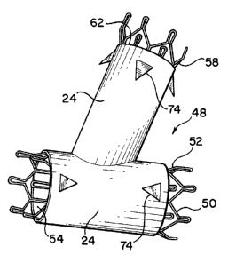
branch legs. Referring to Figures 5 and 6, an anastomosis device 48
capable of providing these support and expansion characteristics is
illustrated. The anastomosis device 48 includes a skeletal frame 50 having
a main leg 52 which is tubular in configuration and is formed to define an
elongated, open ended main chamber 54 having a central longitudinal axis
56. The skeletal frame 50 also includes a branch leg 58 which is connected
at one end 60 to the main leg 52 and which extends angularly outward
therefrom. The branch leg 58 is also tubular in configuration and defines
an elongate branch chamber 62 having a central longitudinal axis 63 which
extends at an angle to the longitudinal axis 56. One end of the branch
chamber 62 opens at 60 into the main chamber 54, while the opposite end
of the branch chamber is open.
CA 02269064 1999-04-16
WO 98/16174 PCT/US97/17927
- 10-
The skeletal frame 50 is shown in the expanded configuration thereof
in Figures 5 and 6 and is preferably formed of wire or a similar elongate
strand or strands of material configured to provide a mesh comprising a
plurality of interconnected open cells 64 which form the main and branch
legs of the skeletal frame. The cells 64 are preferably of a polygonal
configuration when viewed in plan. It is important to note that each cell
is formed by two spaced straight side portions or walls 66 which are
substantially parallel to the central longitudinal axis of either the main
chamber or branch chamber in the leg of the skeletal frame of which the
cell is a part. Each end of a cell is closed by an end wall 68 which extends
at a angle to the longitudinal axis of either the main chamber or the branch
chamber depending upon whether the cell is in the branch leg or the main
leg of the skeletal frame. Preferably, the end walls of each cell are formed
by two inclined end sections 70 and 72 which incline outwardly from the
l5 straight side portions 66 of the cell and meet at an apex centrally of the
cell.
The cells are connected together only along abutting straight elongate
side portions 66, preferably by welding, and the end walls 68 remain
unconnected. Preferably the cells 64 are polygonal and there are six cells
in each circumferential row around the main and branch legs of the skeletal
frame.
The skeletal frame 50 is designed to be collapsed within a delivery
catheter, and to collapse the skeletal frame, the inclined cell end walls 70
and 72 permit the straight elongate side portions of the cell to be moved
together to compress the leg containing the cell toward the central
longitudinal axis of the chamber through the leg. As each cell collapses
from the expanded configuration shown in Figure 6 to a collapsed
...._.~...__. ~ _. _ ___ ._.. .~..~_.~~_~..._.~ .w..... _. _ .._... .
r
CA 02269064 1999-04-16
WO 98/16174 PCT/US97/17927
-11-
configuration, the straight elongate side portions 66 of the cell are
maintained parallel to the respective chamber longitudinal axis. Thus, as
the cells of the main leg 52 of the skeletal frame 50 move between the
expanded configuration and the collapsed configuration, they are maintained
substantially parallel to the central longitudinal axis 56, while the cells of
the branch leg 58 are maintained substantially parallel to the longitudinal
axis 63 as they move between the expanded configuration and the
contracted configuration. Once the cells in the main and branch legs of the
skeletal frame have been moved to the contracted configuration, the branch
leg may be flexed downwardly against the main leg to permit the complete
device to be fit within the bore of a catheter.
As illustrated by Figure 5, the main leg 52 and the branch leg 58 of
the skeletal frame 50 are covered by the fabric 24 bearing the bio-adhesive
of either Figure 2 or Figure 3. It is possible to provide the skeletal frame
50 with inclined laterally projecting barbs 74 which project through the
fabric 24. For many uses, however, the barbs can be completely eliminated
since the combination of the force provided by the skeletal frame 50 and
the bonding effect of the bio-adhesive 26 will hold the anastomosis device
in place and create an effective fluid seal with the luminal walls of two
body vessels.
The skeletal frame 50 may be formed of spring metal, plastic, or
similar material which will expand to the configuration shown in Figure 6,
but preferably, the skeletal frame is formed of a thermal shape memory
material such as Nitinol. The unique characteristic of a thermal shape
memory material is its response to a temperature transformation level below
which the material becomes quite pliable, collapsible and compressible.
Above the temperature transformation level, the material becomes relatively
CA 02269064 1999-04-16
WO 98116174 PCTIUS97/17927
- 12-
rigid though somewhat flexible and returns to its expanded memory shape
with the cell configuration of Figure 6. The inclined end sections 70 and
72 change condition as the skeletal frame is subjected to temperatures above
and below the transition temperature to move the straight side portions of
the cell together or apart.
In the anastomosis device 48 of Figure 5, the material 24 may be an
elastomeric material which expands as the skeletal frame expands but which
applies pressure to the skeletal frame in the expanded condition thereof so
that as the frame passes below the transition temperature, the action of the
elastomeric cover moves the frame to the compressed configuration. It is
possible to make the temperature transition level of the main leg 52 of the
skeletal frame different from the temperature transition level of the branch
leg 58 by, for example, varying the alloy composition of the material
forming the main and branch legs or by varying the annealing temperatures
of the main and branch legs which are used to set the respective transition
temperatures.
As shown by Figure 7, a skeletal frame 76 can be provided with a
main leg 78 which will expand outwardly for a greater distance than will
the branch leg 80. This will cause the main leg to either fit within a larger
vessel, or to provide a greater pressure against the luminal walls of a main
vessel that is the same diameter as a branch vessel applied to the branch leg
80. This greater expansion characteristic is provided by making the cells
64 of the main leg larger than the cells 64 of the branch leg.
_ . v ~ . _ ...~ _._._ ._ _ . ~. _e._ _.. ..~.. ..
CA 02269064 1999-04-16
WO 98116174 PCT/US97/17927
-13-
Industrial A~nlicability
The anastomosis device of the present invention is a unitary unit
which may easily be positioned and used to join two body vessels without
the need for suturing. The device employs automatically activated bio-
adhesives which bind the device to the luminal walls of two tubular body
vessels to create a fluid tight graft.