Note: Descriptions are shown in the official language in which they were submitted.
CA 02269247 1999-04-19
w0 98n7sy3 ~GTIEP9~1105453
Device for Folding a Web of Material
The inven4on relates to a device for folding a web of material in accordance
with the
preamble of the main daim.
U.S. Patent 4,778,441 discloses an apparatus for folding a web of material. It
consists essentially of an embossing roller which has concave and convex
embossing elements as well as a matching counter roller. The paper to be
embossed is guided between the two rollers.
Also disclosed in German OS 42 01 288 is a method and a machine for producing
pleats on paper, frfter material or other such media. This method also
operates with
a pair of notched rollers with indenting knives and anvils. Variable pleating
can be
produced by controlling them accordingly.
A device which produces zig-zag folded filter elements is dlsdosed in U.S.
Patent
3,514,354. Here two star rollers are provided which emboss and simultaneously
fold
the paper. Conveyor belts fallow the star rollers to guide the pleated element
into a
shaping apparatus.
NL 52 575 discloses a toot with which thermoplastic material Can be folded
under
the thermal influence of heat.
A disadvantage in the known embossing or pleating devices is that, in some of
the
materials to be processed, the embossing action is not sufficient to achieve a
precise folded edge. It is espedally disadvantageous that mechanical embossing
by
means of cylinders above a certain maximum speed results in poorer results as
regards the embossing action.
The invention therefiore is addressed to the problem of avoiding the
aforementioned
disadvantages and providing a device for folding a web of material, which will
CA 02269247 1999-04-19
r
w0 98Jx75r3 PCT/EP97/~05453
Z
achieve a high folding output and even in the case of different materials will
emboss
tfiem sufficiently to enable them to be pleated.
This object is achieved, setting out from the preamble of the main claim, by
the
characterizing features thereof.
It is known to perform a welding of laminated materials or nonwoven materials
by
ultrasound. It is also known to cut nonwoven materials or paper by the
ultrasound
method. In the case of the method of the invention, however, neither a cutting
process nor a welding process is carried out,
The substantial advantage of the invention is that supporting the embossing
action
with ultrasound improves the embossing action and shorter cyde times are
achieved. By the input of energy by ultrasound, especially when synthetic
fiber
nonwoven materials are used, plastiflcation is produced in the area of the
fold fine by
the heat that is produced.
An advantage of the use of ultrasound is also to be seen in the fad that is
can be
applied precisely at the desired position. Energy consumption is thus low, and
the
amount of energy applied can be very well controlled.
In accordance with one embodiment of the invention the embossing unit
comprises
at least one anvil roller with an appropriately designed shape and a
sonotrode. This
sonotrode is a part of an oscillating structure with which the necessary
energy can
be applied to and act upon the web of material.
In another embodiment of the device, two embossing units an: to be used. With
these the material web can be embossed on both sides and a zig-zag folded
element can be formed. After the material is provided with the embossing, it
passes
on to a roceiving unit or set-up unit. Here the pleating is performed by the
fact that,
for example, the web of material is introduced into revo>ving spindles. These
spindles permit a precise establishment of the spacing between folds.
CA 02269247 1999-04-19
WO 98/17573 PCT/EP97/05433
3
An advantageous embodiment of the invention envisions making the anvil rolls
or
the sonotrodes modular, so that they can be quickly exchanged and an
adaptation
to the desired embossing structure will be very easy to achieve. A method for
producing a pleated element provides, according to~the invention, for feeding
a web
of material through a feeder to an embossing unit. Ultrasound is
simultaneously
applied to the embossing unit to assist the embossing action. With this method
it is
possible to produce a filter element from different materials, especially also
from
synthetic nonwoven material, which can be produced in an economical manner.
In another embodiment of the invention, a synthetic resin element composed of
active carbon or doped with active carbon is embossed, thus producing a filter
element which in addition to particles, also absorbs air pollutants and gases.
These and other features of preferred embodiments of the invention will be
found
not only in the claims but also in the description and the drawings, it being
possible
for the individual features to be realized individually or together in the
form of sub-
combinations in embodiments of the invention and in other fields, and may
represent
advantageous and independently patentable embodiments for which protection is
hereby claimed.
The invention will be explained in further detail with reference to working
embodiments.
Figure 1 shows a schematic layout of a device for folding a web of material,
Figure 2 shows a schematic layout of another working embodiment of a device
for
folding a web of material, and
Figure 3 shows a detail view of a sonotrode.
CA 02269247 1999-04-19
WO 98/17573 PCT/EP97/05453
4
In the schematic diagram of the device in Figure 1 an endless web 1 of filter
material
is shown. This is initially embossed in an embossing station 10. The embossing
station 10 is comprised of two anvil rolls 13 and 14 which are equipped with
embossing punches 15 and anvils 16. The filter material web 1 unwound from a
roll
17 is thereby provided on alternating sides with a crease. The web of filter
material
passes from the embossing station 10 into the sphere of influence of a folding
station 11, namely between two cogbelts 2 a and 2 b which fold the embossed
web
1 in a defined manner. After the cogbelts the pleated web 1 in conveyed in a
defined manner in a worm screw 3. This worm screw 3 has a variable pitch and
can
gather the pleated material together with a certain spacing between pleats. At
the
end a severing device 12 separates the individual fitter elements which are
delivered
by a comb-like element 6 to a transfer station 5. The embossing punches 15
arranged on the embossing rollers 13 and 14 are each provided with a sonotrode
or
are constructed in the form of sonotrodes and are excited by an ultrasound
generator. The sonotrode or the embossing punch thus produces - through a
friction effect and local heating - a plastification of the web composed of a
nonwoven material and hence a contour corresponding to a rippled profile.
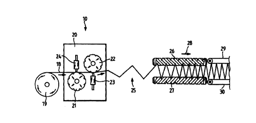
Figure 2 shows a schematic illustration of an apparatus which is a variant of
the
apparatus shown in Figure 1. A web 18 of filter material is conveyed from a
roll 19
to an embossing module 20. This embossing module is comprised of anvil roller
21
and anvil roller 22, as well as the sonotrodes 23 and 24 as part of a so-
called
oscillating structure. As the web passes through it, the sonotrodes emboss it
at the
intended places, so that thereafter a fold is formed in the area 25. In order
to define
the pleat spacing, two spindles 26 and 27 are provided, into which the web
passes.
These spindles have a diminishing pitch, so that the distance between pleats
decreases in the direction of the arrow 28. After the final distance between
pleats is
established at the right-hand end of the spindles, the web is transferred to
two
conveyor belts 29 and 30. These conveyor belts carry the filter material web
to a
packaging and cutting apparatus, not shown here.
CA 02269247 1999-04-19
WO 98/17573 PCT/EP97l05453
Figure 3 shows on an enlarged scale the principle of the ultrasound-aided
embossing. Here are represented a sonotrode 24 and the anvil roller or anvil
21
through which the filter material web 18 is moved. During the transport of the
filter
material, the application of ultrasound at the tip 31 of the sonotrode 24
causes a
brief heating of the web within a defined area and thus leads to a permanent
deformation. This permanent deformation forms the crease locations 32. The
size
of the gap between the sonotrode and the embossing roller 21 can be made
variable
and thus can be optimally adapted to the web of filter material. It is also
possible to
emboss material coated with active carbon or material doped with active
carbon.
Here, again, the variability as regards the embossing depth is advantageous,
especially when materials are used in which active carbon is embedded in a
kind of
multi-layer arrangement and damage to these layers must be avoided.
The steps in the process of manufacturing a pleated filter element are:
The weakening of the material with the aid of ultrasound and thus also the
simultaneous warming of the material,
thereafter the setting up of the filter material web in spindles or conveyor
belts,
and then the fixing of the filter element by appropriate known measures such
as beads of glue, side strips, or the like.
If a material doped with active carbon is used, the ultrasound process makes
it
possible to reduce the size of the active carbon particles at the crease. This
has the
advantage on the one hand that damage to the material is avoided and on the
other
hand that the crease location can be very accurately defined even when active
carbon particles are used.
It is advantageous to adjust the ultrasound action and thus the warming of the
material at the crease location so that, in the case of a polyester nonwoven
material,
a localized warming of about 110 to 120°C occurs. This heating above
the glass
transition temperature results in a lasting deformation, while the crease
nevertheless
remains plastic.