Language selection

Search

Patent 2269308 Summary

Third-party information liability

Some of the information on this Web page has been provided by external sources. The Government of Canada is not responsible for the accuracy, reliability or currency of the information supplied by external sources. Users wishing to rely upon this information should consult directly with the source of the information. Content provided by external sources is not subject to official languages, privacy and accessibility requirements.

Claims and Abstract availability

Any discrepancies in the text and image of the Claims and Abstract are due to differing posting times. Text of the Claims and Abstract are posted:

  • At the time the application is open to public inspection;
  • At the time of issue of the patent (grant).
(12) Patent Application: (11) CA 2269308
(54) English Title: INSTALLATION DEVICE FOR A VEHICLE
(54) French Title: DISPOSITIF D'INSTALLATION POUR VEHICULE
Status: Deemed Abandoned and Beyond the Period of Reinstatement - Pending Response to Notice of Disregarded Communication
Bibliographic Data
(51) International Patent Classification (IPC):
  • B60R 11/02 (2006.01)
  • B60R 7/06 (2006.01)
  • B60R 11/00 (2006.01)
(72) Inventors :
  • MIEGLITZ, HANS-HELMUT (Germany)
  • SCHIDAN, ALEXANDER (Germany)
  • ROUGHTON, CHARLES (Germany)
(73) Owners :
  • JOHNSON CONTROLS INTERIORS GMBH
(71) Applicants :
  • JOHNSON CONTROLS INTERIORS GMBH (Germany)
(74) Agent: MACRAE & CO.
(74) Associate agent:
(45) Issued:
(22) Filed Date: 1999-04-16
(41) Open to Public Inspection: 1999-10-18
Availability of licence: N/A
Dedicated to the Public: N/A
(25) Language of filing: English

Patent Cooperation Treaty (PCT): No

(30) Application Priority Data:
Application No. Country/Territory Date
198 17 302.4 (Germany) 1998-04-18

Abstracts

English Abstract


In accordance with the teachings of the present invention, an installation
device for
a vehicle is disclosed which in particular is for the releasable mounting of a
handheld mobile
phone. The installation device is designed with a housing (2) which is opened
toward the
front and is to be arranged on a receiving shaft of a vehicle part (1), such
as an instrument
panel, console, or the like, with a carrying part (16) which can be pivoted
into, and out of,
the housing (2) via a substantially vertically aligned axis of rotation (5),
with a bearing plate
(7) which is arranged on the carrying part (16) and is intended for the mobile
phone (12)
when the carrying part (16) has been pivoted out of the housing (2), and with
a substantially
horizontally aligned pivot axis (11) between the carrying part (16) and a
bearing plate (7).


Claims

Note: Claims are shown in the official language in which they were submitted.

What is Claimed is:
1. An installation device for a vehicle, in particular for the releasable
mounting
of a handheld mobile phone (12), said installation device comprising:
a housing (2) which is open toward the front and is to be arranged in a
receiving shaft
of a vehicle part (1), such as instrument panel, console or the like;
a carrying part (16) which can be pivoted into, and out of, the housing (2)
via a
substantially vertically aligned axis of rotation (5);
a bearing plate (7) which is arranged on the carrying part (16) and which is
intended
to support the mobile phone (12) when the carrying part (16) has been pivoted
out of the
housing (2); and
a substantially horizontally aligned pivot axis (11) between the carrying part
(16) and
the bearing plate (7).
2. The installation device as claimed in Claim 1 wherein the substantially
vertically aligned axis of rotation (5) is located in a front corner region of
the housing (2).
3. The installation device as claimed in Claim 1 wherein the bearing plate (7)
can
be moved into an oblique position counter to the force of a restoring spring
(13).
4. The installation device as claimed in Claim 1 wherein the length of the
bearing plate (7) is less than the length of the mobile phone (12).
6

5. The installation device as claimed in Claim 1 wherein the bearing plate (7)
has
a stop (9) at its free end for supporting the mobile phone (12).
6. The installation device as claimed in Claim 1 wherein buffers (8) for
supporting the mobile phone (12) are laterally arranged on the carrying part
(16).
7. The installation device as claimed in Claim 1 wherein, when the carrying
part
(16) has been pivoted in, the housing opening is closed off by a first screen
(3), which is
formed rigidly with the carrying part (16), and by a second screen (4), which
is articulated
on the housing (2) in the region of the vertical axis of rotation (5) via a
substantially
horizontally aligned axis of rotation (6).
8. The installation device as claimed in Claim 7, wherein the second screen
(4),
which is articulated on the housing (2), is shorter than the first screen (3)
and can be pivoted
open by a run-on slope (10) arranged on the carrying part (16).
7

Description

Note: Descriptions are shown in the official language in which they were submitted.


CA 02269308 1999-04-16
Attorney Docket No.: 1056A-012125
PATENT
INSTALLATION DEVICE FOR A VEHICLE
This invention generally relates to an installation device for a vehicle and,
more
particularly, to a releasable mounting for a handheld mobile phone.
Various arrangements and installation devices have been previously used for
securing
a mobile phone within a motor vehicle. One such arrangement is disclosed by DE
195 39
784 C2. This reference in particular discloses the releasable mounting of a
handheld phone
and provides a receiving compartment which is guided in a longitudinally
movable manner
in a housing open toward the front and is intended for a handheld phone
retained in a
clamping manner by the receiving compartment. The receiving compartment
comprises two
compartment parts which are arranged one behind the other in the axial
direction and are of
different lengths, of which the longer compartment part serves for receiving
the handheld
phone in a suitable manner and can be drawn out of the housing to the full
extent and is
connected to the shorter compartment which remains permanently in the housing
via a hinge
1 S and can be pivoted perpendicularly with respect to the slide direction.
In accordance with the teachings of the present invention, it is an obj ect of
the present
invention to make available an installation device which is simplified in
relation to, and of

CA 02269308 1999-04-16
Attorney Docket No.: 1056A-012125
considerably smaller dimensions than, the above referenced apparatus and
others in the field
of use.
The installation device which is provided according to the invention in order
to
achieve this objective has the features of Claim 1, while advantageous
configurations and
developments of the invention are defined in the depending subclaims.
In accordance with the teachings of a preferred embodiment of the present
invention,
a device is provided which makes it possible to position a mobile phone in the
use position
in order to ensure quick access to the phone, to provide a well suited central
storage area, to
bring the mobile display and the key pad into a position in which they can be
seen, to aid
hands free talking by the proximity of the holder position, to avoid slipping
of the mobile
phone during travel, to make it more difficult for one to forget the mobile
phone when one
is leaving the vehicle, and generally to render telephoning from inside ones
vehicle, if not
entirely avoidable, then safer by the design of the surroundings and a
reduction in the amount
of holding on the part of the driver.
BR_TEF DES TPTION OF TH . DR A WTNC'T~
The various advantages of the present invention will become apparent to one
skilled
in the art upon reading the following specification and by reference to the
drawings in which:
Figure 1 is a front view of the installation device made in accordance with
the present
Invention;
Figure 2 is a plan view of the installation device in the not-in-use position;
Figure 3 is a plan view of the installation device in the use position;
Figure 4 is a sectional view generally taken along lines I-I in Figure 3; and
2

CA 02269308 1999-04-16
Attorney Docket No.: 1056A-012125
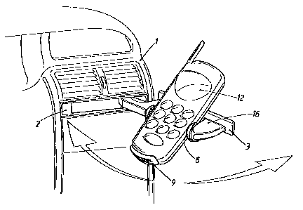
Figure 5 is a perspective view of the installation device of the present
invention fitted
with a mobile phone and shown in the in use position.
RETAILED DES RTPTION OF TH . PREFERRED EMBODIMENT
The following description of the preferred embodiment is merely exemplary in
nature
and is in no way intended to limit the invention, or its application, or uses.
Referring to Figure 1, there is shown a vehicle part 1, which may be a cockpit
or
center console neck or the like, with an installation unit arranged on a
receiving shaft of said
neck. Of the installation unit, it is possible to see the frame of a housing 2
and the front
subdivided into two screens 3 and 4.
The installation device comprises the housing 2 and a carrying part 16 which
can be
pivoted into the housing 2 (shown in Figures 1 and 2), and pivoted out of the
housing 2
(shown in Figures 3-5), via a substantially vertically aligned axis of
rotation 5. Arranged on
the carrying part 16 is a bearing plate 7 on which a mobile phone 12 can be
deposited when
the bearing plate 7 is located in the position in which it has been pivoted
out of the housing
1 S 2. The bearing plate 7 is articulated on the carrying part 16 by a
substantially horizontally
aligned pivot axis 11. The pivoted-down, oblique position of the bearing plate
7 is shown
in Figures 4 and 5 and is approximately 45 degrees from horizontal, which has
proven to be
optimum for the positioning of the mobile phone 12. The oblique position is
brought about
by the mobile phone 12 being placed in such a position or being placed in the
position by its
own weight. The force of a restoring spring 13 tries to transfer the bearing
plate 7 into a
horizontal position thereby allowing the carrying part 16 to be guided back
into the housing
2.
3

CA 02269308 1999-04-16
Attorney Docket No.: 1056A-012125
Located at the free end of the bearing plate, which is considerably shorter
than the
length of most commercially available mobile phones 12, is a stop 9 for
supporting the
mobile phone 12. For supporting the mobile phone 12 laterally, use is made of
buffers 8
which are arranged on the carrying part 16 to the left and right lateral
portions along side the
bearing plate 7.
The previously mentioned screens 3 and 4 are used for closing off the housing
opening in the not-in-use position of the installation device. In the present
embodiment, the
screen 3 is connected rigidly to the carrying part 16. For example, the
carrying part 16 and
the screen 3 can be formed as an integral plastic injection molded piece. The
screen 4, in
contrast, is a separate component, which is connected to the housing 2 via an
axis of rotation
6. The axis of rotation 6 is adj acent to the top border region of the screen
4, with the result
that, on account of its own weight, the screen tries to assume its covering
position. For the
purposes of opening the screen 4, use is made of a run-on slope 10 which is
arranged on the
carrying part 16 and, when the carrying part 16 is pivoted open, moves through
the free space
15 and then against the rear side of the screen 4.
The axis of rotation 5 is positioned in a front corner region of the housing
2, with the
result that there is a relatively large pivoting region for the carrying part
16. The pivot axis
11 is arranged on the carrying part 16, adjacent to the screen 3.
In order to increase the ease of operation of the present invention, the
installation
device may be provided with an automatic opening mechanism known within the
art. Tip-
matic or push-push mechanisms are just two of the means currently known in the
art. A
push-point indicator, designated by 14 in Figure 1, is used in conjunction
with such a
mechanism.
4

CA 02269308 1999-04-16
Attorney Docket No.: 1056A-012125
The foregoing discussion discloses and describes a preferred embodiment of the
present invention. One skilled in the art will readily recognize from such
discussion, and
from the accompanying drawings and claims, that various changes,
modifications, and
variations can be made therein without departing from the true spirit and fair
scope of the
invention as defined in the following claims.
5

Representative Drawing
A single figure which represents the drawing illustrating the invention.
Administrative Status

2024-08-01:As part of the Next Generation Patents (NGP) transition, the Canadian Patents Database (CPD) now contains a more detailed Event History, which replicates the Event Log of our new back-office solution.

Please note that "Inactive:" events refers to events no longer in use in our new back-office solution.

For a clearer understanding of the status of the application/patent presented on this page, the site Disclaimer , as well as the definitions for Patent , Event History , Maintenance Fee  and Payment History  should be consulted.

Event History

Description Date
Inactive: IPC expired 2024-01-01
Inactive: IPC expired 2015-01-01
Inactive: IPC from MCD 2006-03-12
Application Not Reinstated by Deadline 2003-04-16
Time Limit for Reversal Expired 2003-04-16
Deemed Abandoned - Failure to Respond to Maintenance Fee Notice 2002-04-16
Letter Sent 2001-03-23
Inactive: Single transfer 2001-02-27
Letter Sent 2000-08-11
Extension of Time for Taking Action Requirements Determined Compliant 2000-08-11
Inactive: Extension of time for transfer 2000-07-18
Inactive: Cover page published 1999-11-02
Application Published (Open to Public Inspection) 1999-10-18
Inactive: Cover page published 1999-10-17
Inactive: First IPC assigned 1999-06-08
Inactive: Courtesy letter - Evidence 1999-05-25
Inactive: Filing certificate - No RFE (English) 1999-05-19
Filing Requirements Determined Compliant 1999-05-19
Application Received - Regular National 1999-05-19

Abandonment History

Abandonment Date Reason Reinstatement Date
2002-04-16

Maintenance Fee

The last payment was received on 2001-04-17

Note : If the full payment has not been received on or before the date indicated, a further fee may be required which may be one of the following

  • the reinstatement fee;
  • the late payment fee; or
  • additional fee to reverse deemed expiry.

Please refer to the CIPO Patent Fees web page to see all current fee amounts.

Fee History

Fee Type Anniversary Year Due Date Paid Date
Application fee - standard 1999-04-16
Extension of time 2000-07-18
Registration of a document 2001-02-27
MF (application, 2nd anniv.) - standard 02 2001-04-17 2001-04-17
Owners on Record

Note: Records showing the ownership history in alphabetical order.

Current Owners on Record
JOHNSON CONTROLS INTERIORS GMBH
Past Owners on Record
ALEXANDER SCHIDAN
CHARLES ROUGHTON
HANS-HELMUT MIEGLITZ
Past Owners that do not appear in the "Owners on Record" listing will appear in other documentation within the application.
Documents

To view selected files, please enter reCAPTCHA code :


To view images, click a link in the Document Description column. To download the documents, select one or more checkboxes in the first column and then click the "Download Selected in PDF format (Zip Archive)" or the "Download Selected as Single PDF" button.

List of published and non-published patent-specific documents on the CPD .

If you have any difficulty accessing content, you can call the Client Service Centre at 1-866-997-1936 or send them an e-mail at CIPO Client Service Centre.


Document
Description 
Date
(yyyy-mm-dd) 
Number of pages   Size of Image (KB) 
Representative drawing 1999-10-06 1 13
Description 1999-04-16 5 176
Claims 1999-04-16 2 54
Abstract 1999-04-16 1 22
Drawings 1999-04-16 5 84
Cover Page 1999-11-02 1 42
Representative drawing 2007-02-02 1 15
Filing Certificate (English) 1999-05-19 1 165
Request for evidence or missing transfer 2000-04-18 1 109
Reminder of maintenance fee due 2000-12-19 1 112
Courtesy - Certificate of registration (related document(s)) 2001-03-23 1 113
Courtesy - Abandonment Letter (Maintenance Fee) 2002-05-14 1 183
Correspondence 1999-05-25 1 30
Correspondence 2000-07-18 2 45
Correspondence 2000-08-11 1 8