Sélection de la langue

Search

Sommaire du brevet 2269308 

Énoncé de désistement de responsabilité concernant l'information provenant de tiers

Une partie des informations de ce site Web a été fournie par des sources externes. Le gouvernement du Canada n'assume aucune responsabilité concernant la précision, l'actualité ou la fiabilité des informations fournies par les sources externes. Les utilisateurs qui désirent employer cette information devraient consulter directement la source des informations. Le contenu fourni par les sources externes n'est pas assujetti aux exigences sur les langues officielles, la protection des renseignements personnels et l'accessibilité.

Disponibilité de l'Abrégé et des Revendications

L'apparition de différences dans le texte et l'image des Revendications et de l'Abrégé dépend du moment auquel le document est publié. Les textes des Revendications et de l'Abrégé sont affichés :

  • lorsque la demande peut être examinée par le public;
  • lorsque le brevet est émis (délivrance).
(12) Demande de brevet: (11) CA 2269308
(54) Titre français: DISPOSITIF D'INSTALLATION POUR VEHICULE
(54) Titre anglais: INSTALLATION DEVICE FOR A VEHICLE
Statut: Réputée abandonnée et au-delà du délai pour le rétablissement - en attente de la réponse à l’avis de communication rejetée
Données bibliographiques
(51) Classification internationale des brevets (CIB):
  • B60R 11/02 (2006.01)
  • B60R 7/06 (2006.01)
  • B60R 11/00 (2006.01)
(72) Inventeurs :
  • MIEGLITZ, HANS-HELMUT (Allemagne)
  • SCHIDAN, ALEXANDER (Allemagne)
  • ROUGHTON, CHARLES (Allemagne)
(73) Titulaires :
  • JOHNSON CONTROLS INTERIORS GMBH
(71) Demandeurs :
  • JOHNSON CONTROLS INTERIORS GMBH (Allemagne)
(74) Agent: MACRAE & CO.
(74) Co-agent:
(45) Délivré:
(22) Date de dépôt: 1999-04-16
(41) Mise à la disponibilité du public: 1999-10-18
Licence disponible: S.O.
Cédé au domaine public: S.O.
(25) Langue des documents déposés: Anglais

Traité de coopération en matière de brevets (PCT): Non

(30) Données de priorité de la demande:
Numéro de la demande Pays / territoire Date
198 17 302.4 (Allemagne) 1998-04-18

Abrégés

Abrégé anglais


In accordance with the teachings of the present invention, an installation
device for
a vehicle is disclosed which in particular is for the releasable mounting of a
handheld mobile
phone. The installation device is designed with a housing (2) which is opened
toward the
front and is to be arranged on a receiving shaft of a vehicle part (1), such
as an instrument
panel, console, or the like, with a carrying part (16) which can be pivoted
into, and out of,
the housing (2) via a substantially vertically aligned axis of rotation (5),
with a bearing plate
(7) which is arranged on the carrying part (16) and is intended for the mobile
phone (12)
when the carrying part (16) has been pivoted out of the housing (2), and with
a substantially
horizontally aligned pivot axis (11) between the carrying part (16) and a
bearing plate (7).

Revendications

Note : Les revendications sont présentées dans la langue officielle dans laquelle elles ont été soumises.


What is Claimed is:
1. An installation device for a vehicle, in particular for the releasable
mounting
of a handheld mobile phone (12), said installation device comprising:
a housing (2) which is open toward the front and is to be arranged in a
receiving shaft
of a vehicle part (1), such as instrument panel, console or the like;
a carrying part (16) which can be pivoted into, and out of, the housing (2)
via a
substantially vertically aligned axis of rotation (5);
a bearing plate (7) which is arranged on the carrying part (16) and which is
intended
to support the mobile phone (12) when the carrying part (16) has been pivoted
out of the
housing (2); and
a substantially horizontally aligned pivot axis (11) between the carrying part
(16) and
the bearing plate (7).
2. The installation device as claimed in Claim 1 wherein the substantially
vertically aligned axis of rotation (5) is located in a front corner region of
the housing (2).
3. The installation device as claimed in Claim 1 wherein the bearing plate (7)
can
be moved into an oblique position counter to the force of a restoring spring
(13).
4. The installation device as claimed in Claim 1 wherein the length of the
bearing plate (7) is less than the length of the mobile phone (12).
6

5. The installation device as claimed in Claim 1 wherein the bearing plate (7)
has
a stop (9) at its free end for supporting the mobile phone (12).
6. The installation device as claimed in Claim 1 wherein buffers (8) for
supporting the mobile phone (12) are laterally arranged on the carrying part
(16).
7. The installation device as claimed in Claim 1 wherein, when the carrying
part
(16) has been pivoted in, the housing opening is closed off by a first screen
(3), which is
formed rigidly with the carrying part (16), and by a second screen (4), which
is articulated
on the housing (2) in the region of the vertical axis of rotation (5) via a
substantially
horizontally aligned axis of rotation (6).
8. The installation device as claimed in Claim 7, wherein the second screen
(4),
which is articulated on the housing (2), is shorter than the first screen (3)
and can be pivoted
open by a run-on slope (10) arranged on the carrying part (16).
7

Description

Note : Les descriptions sont présentées dans la langue officielle dans laquelle elles ont été soumises.

CA 02269308 1999-04-16
Attorney Docket No.: 1056A-012125
PATENT
INSTALLATION DEVICE FOR A VEHICLE
This invention generally relates to an installation device for a vehicle and,
more
particularly, to a releasable mounting for a handheld mobile phone.
Various arrangements and installation devices have been previously used for
securing
a mobile phone within a motor vehicle. One such arrangement is disclosed by DE
195 39
784 C2. This reference in particular discloses the releasable mounting of a
handheld phone
and provides a receiving compartment which is guided in a longitudinally
movable manner
in a housing open toward the front and is intended for a handheld phone
retained in a
clamping manner by the receiving compartment. The receiving compartment
comprises two
compartment parts which are arranged one behind the other in the axial
direction and are of
different lengths, of which the longer compartment part serves for receiving
the handheld
phone in a suitable manner and can be drawn out of the housing to the full
extent and is
connected to the shorter compartment which remains permanently in the housing
via a hinge
1 S and can be pivoted perpendicularly with respect to the slide direction.
In accordance with the teachings of the present invention, it is an obj ect of
the present
invention to make available an installation device which is simplified in
relation to, and of

CA 02269308 1999-04-16
Attorney Docket No.: 1056A-012125
considerably smaller dimensions than, the above referenced apparatus and
others in the field
of use.
The installation device which is provided according to the invention in order
to
achieve this objective has the features of Claim 1, while advantageous
configurations and
developments of the invention are defined in the depending subclaims.
In accordance with the teachings of a preferred embodiment of the present
invention,
a device is provided which makes it possible to position a mobile phone in the
use position
in order to ensure quick access to the phone, to provide a well suited central
storage area, to
bring the mobile display and the key pad into a position in which they can be
seen, to aid
hands free talking by the proximity of the holder position, to avoid slipping
of the mobile
phone during travel, to make it more difficult for one to forget the mobile
phone when one
is leaving the vehicle, and generally to render telephoning from inside ones
vehicle, if not
entirely avoidable, then safer by the design of the surroundings and a
reduction in the amount
of holding on the part of the driver.
BR_TEF DES TPTION OF TH . DR A WTNC'T~
The various advantages of the present invention will become apparent to one
skilled
in the art upon reading the following specification and by reference to the
drawings in which:
Figure 1 is a front view of the installation device made in accordance with
the present
Invention;
Figure 2 is a plan view of the installation device in the not-in-use position;
Figure 3 is a plan view of the installation device in the use position;
Figure 4 is a sectional view generally taken along lines I-I in Figure 3; and
2

CA 02269308 1999-04-16
Attorney Docket No.: 1056A-012125
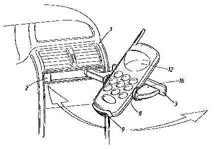
Figure 5 is a perspective view of the installation device of the present
invention fitted
with a mobile phone and shown in the in use position.
RETAILED DES RTPTION OF TH . PREFERRED EMBODIMENT
The following description of the preferred embodiment is merely exemplary in
nature
and is in no way intended to limit the invention, or its application, or uses.
Referring to Figure 1, there is shown a vehicle part 1, which may be a cockpit
or
center console neck or the like, with an installation unit arranged on a
receiving shaft of said
neck. Of the installation unit, it is possible to see the frame of a housing 2
and the front
subdivided into two screens 3 and 4.
The installation device comprises the housing 2 and a carrying part 16 which
can be
pivoted into the housing 2 (shown in Figures 1 and 2), and pivoted out of the
housing 2
(shown in Figures 3-5), via a substantially vertically aligned axis of
rotation 5. Arranged on
the carrying part 16 is a bearing plate 7 on which a mobile phone 12 can be
deposited when
the bearing plate 7 is located in the position in which it has been pivoted
out of the housing
1 S 2. The bearing plate 7 is articulated on the carrying part 16 by a
substantially horizontally
aligned pivot axis 11. The pivoted-down, oblique position of the bearing plate
7 is shown
in Figures 4 and 5 and is approximately 45 degrees from horizontal, which has
proven to be
optimum for the positioning of the mobile phone 12. The oblique position is
brought about
by the mobile phone 12 being placed in such a position or being placed in the
position by its
own weight. The force of a restoring spring 13 tries to transfer the bearing
plate 7 into a
horizontal position thereby allowing the carrying part 16 to be guided back
into the housing
2.
3

CA 02269308 1999-04-16
Attorney Docket No.: 1056A-012125
Located at the free end of the bearing plate, which is considerably shorter
than the
length of most commercially available mobile phones 12, is a stop 9 for
supporting the
mobile phone 12. For supporting the mobile phone 12 laterally, use is made of
buffers 8
which are arranged on the carrying part 16 to the left and right lateral
portions along side the
bearing plate 7.
The previously mentioned screens 3 and 4 are used for closing off the housing
opening in the not-in-use position of the installation device. In the present
embodiment, the
screen 3 is connected rigidly to the carrying part 16. For example, the
carrying part 16 and
the screen 3 can be formed as an integral plastic injection molded piece. The
screen 4, in
contrast, is a separate component, which is connected to the housing 2 via an
axis of rotation
6. The axis of rotation 6 is adj acent to the top border region of the screen
4, with the result
that, on account of its own weight, the screen tries to assume its covering
position. For the
purposes of opening the screen 4, use is made of a run-on slope 10 which is
arranged on the
carrying part 16 and, when the carrying part 16 is pivoted open, moves through
the free space
15 and then against the rear side of the screen 4.
The axis of rotation 5 is positioned in a front corner region of the housing
2, with the
result that there is a relatively large pivoting region for the carrying part
16. The pivot axis
11 is arranged on the carrying part 16, adjacent to the screen 3.
In order to increase the ease of operation of the present invention, the
installation
device may be provided with an automatic opening mechanism known within the
art. Tip-
matic or push-push mechanisms are just two of the means currently known in the
art. A
push-point indicator, designated by 14 in Figure 1, is used in conjunction
with such a
mechanism.
4

CA 02269308 1999-04-16
Attorney Docket No.: 1056A-012125
The foregoing discussion discloses and describes a preferred embodiment of the
present invention. One skilled in the art will readily recognize from such
discussion, and
from the accompanying drawings and claims, that various changes,
modifications, and
variations can be made therein without departing from the true spirit and fair
scope of the
invention as defined in the following claims.
5

Dessin représentatif
Une figure unique qui représente un dessin illustrant l'invention.
États administratifs

2024-08-01 : Dans le cadre de la transition vers les Brevets de nouvelle génération (BNG), la base de données sur les brevets canadiens (BDBC) contient désormais un Historique d'événement plus détaillé, qui reproduit le Journal des événements de notre nouvelle solution interne.

Veuillez noter que les événements débutant par « Inactive : » se réfèrent à des événements qui ne sont plus utilisés dans notre nouvelle solution interne.

Pour une meilleure compréhension de l'état de la demande ou brevet qui figure sur cette page, la rubrique Mise en garde , et les descriptions de Brevet , Historique d'événement , Taxes périodiques et Historique des paiements devraient être consultées.

Historique d'événement

Description Date
Inactive : CIB expirée 2024-01-01
Inactive : CIB expirée 2015-01-01
Inactive : CIB de MCD 2006-03-12
Demande non rétablie avant l'échéance 2003-04-16
Le délai pour l'annulation est expiré 2003-04-16
Réputée abandonnée - omission de répondre à un avis sur les taxes pour le maintien en état 2002-04-16
Lettre envoyée 2001-03-23
Inactive : Transfert individuel 2001-02-27
Lettre envoyée 2000-08-11
Exigences de prorogation de délai pour l'accomplissement d'un acte - jugée conforme 2000-08-11
Inactive : Prorogation de délai lié aux transferts 2000-07-18
Inactive : Page couverture publiée 1999-11-02
Demande publiée (accessible au public) 1999-10-18
Inactive : Page couverture publiée 1999-10-17
Inactive : CIB en 1re position 1999-06-08
Inactive : Lettre de courtoisie - Preuve 1999-05-25
Inactive : Certificat de dépôt - Sans RE (Anglais) 1999-05-19
Exigences de dépôt - jugé conforme 1999-05-19
Demande reçue - nationale ordinaire 1999-05-19

Historique d'abandonnement

Date d'abandonnement Raison Date de rétablissement
2002-04-16

Taxes périodiques

Le dernier paiement a été reçu le 2001-04-17

Avis : Si le paiement en totalité n'a pas été reçu au plus tard à la date indiquée, une taxe supplémentaire peut être imposée, soit une des taxes suivantes :

  • taxe de rétablissement ;
  • taxe pour paiement en souffrance ; ou
  • taxe additionnelle pour le renversement d'une péremption réputée.

Veuillez vous référer à la page web des taxes sur les brevets de l'OPIC pour voir tous les montants actuels des taxes.

Historique des taxes

Type de taxes Anniversaire Échéance Date payée
Taxe pour le dépôt - générale 1999-04-16
Prorogation de délai 2000-07-18
Enregistrement d'un document 2001-02-27
TM (demande, 2e anniv.) - générale 02 2001-04-17 2001-04-17
Titulaires au dossier

Les titulaires actuels et antérieures au dossier sont affichés en ordre alphabétique.

Titulaires actuels au dossier
JOHNSON CONTROLS INTERIORS GMBH
Titulaires antérieures au dossier
ALEXANDER SCHIDAN
CHARLES ROUGHTON
HANS-HELMUT MIEGLITZ
Les propriétaires antérieurs qui ne figurent pas dans la liste des « Propriétaires au dossier » apparaîtront dans d'autres documents au dossier.
Documents

Pour visionner les fichiers sélectionnés, entrer le code reCAPTCHA :


Pour visualiser une image, cliquer sur un lien dans la colonne description du document. Pour télécharger l'image (les images), cliquer l'une ou plusieurs cases à cocher dans la première colonne et ensuite cliquer sur le bouton "Télécharger sélection en format PDF (archive Zip)" ou le bouton "Télécharger sélection (en un fichier PDF fusionné)".

Liste des documents de brevet publiés et non publiés sur la BDBC .

Si vous avez des difficultés à accéder au contenu, veuillez communiquer avec le Centre de services à la clientèle au 1-866-997-1936, ou envoyer un courriel au Centre de service à la clientèle de l'OPIC.


Description du
Document 
Date
(aaaa-mm-jj) 
Nombre de pages   Taille de l'image (Ko) 
Dessin représentatif 1999-10-06 1 13
Description 1999-04-16 5 176
Revendications 1999-04-16 2 54
Abrégé 1999-04-16 1 22
Dessins 1999-04-16 5 84
Page couverture 1999-11-02 1 42
Dessin représentatif 2007-02-02 1 15
Certificat de dépôt (anglais) 1999-05-19 1 165
Demande de preuve ou de transfert manquant 2000-04-18 1 109
Rappel de taxe de maintien due 2000-12-19 1 112
Courtoisie - Certificat d'enregistrement (document(s) connexe(s)) 2001-03-23 1 113
Courtoisie - Lettre d'abandon (taxe de maintien en état) 2002-05-14 1 183
Correspondance 1999-05-25 1 30
Correspondance 2000-07-18 2 45
Correspondance 2000-08-11 1 8