Note: Descriptions are shown in the official language in which they were submitted.
CA 02269351 1999-04-20
WO 98118565 PCTIUS97/15848
SQUEEZE DISPENSER FOR POWDER
FIELD OF THE INVENTION
The present invention relates to dispensers for powders, and more particularly
to
such dispensers wherein the powder is moisture absorbent, therefore requiring
powder
protection from long term exposure to moisture contained in ambient air when
the
dispenser is not in use. Even more particularly, the present invention relates
to squeeze
dispensers having compliant discharge valves which self seal the dispenser
after fluid
discharge.
BACKGROUND OF THE INVENTION
Powder dispensing is not as well understood as liquid dispensing because
powder dispensing involves a two-phase fluid containing a compressible gas and
solid
particles. Even powders dispensed by gravity or by shaking a canister have air
mixed
with the solid particles. Flowability of a powder is believed to be influenced
by multiple
factors, including the size and shape of the particles, the tendency for
particles to stick to
each other, the density of particles, and the volume of air between particles.
Particles
may stick to each other due to electrostatic attraction as well as adhesive
forces.
Moisture absorbent powders in particular are prone to caking and resist flow
when
moisture is sufficiently absorbed. Therefore, moisture absorbing powders are
typically
contained in relatively air-tight dispensers so that they remain flowable for
dispensing
after being stored for extended periods in the presence of moist ambient air,
such as
often exists in a bathroom.
Moisture absorbent powders are useful in maintaining body surfaces dry and
feeling soft. Where body surfaces are substantially smooth and upward facing,
it is
relatively easy to shake a powder from a canister onto the surface and
distribute the
powder evenly by using one's fingers. However, delivering powder to a body
surface
having hair or which faces substantially horizontal or downward is benefited
by a
delivery system which effectively squirts a pattern of powder onto the surface
without
the need for finger distribution of the powder. Spray type dispensers are
generally
preferred for such applications.
Squeeze type powder sprayers are known in the art. In one version a resilient
bulb is squeezed to cause a burst of air to flow past a container of powder.
The powder
is drawn into and mixed with the airstream, presumably because the movement of
the air
CA 02269351 1999-04-20
WO 98118565 PCT/US97/15848
2
generates a low pressure zone adjacent the powder surface. Bulb type powder
dispensers are typically limited to very low powder doses.
Squeezebottles which contain powder and have an air headspace are another
version, wherein powder is discharged by squeezing the bottle to cause
headspace air to
push a portion of powder and air out of the bottle. Air pressure may force the
powder
out an open orifice as in U.S. Patent No. 2,450,205 to Rose or U.S. Patent No.
2,840,277
to Bach. One disadvantage of these prior art dispensers is that their
discharge orifices
are always open, thereby exposing contained powder to moisture. Prior art
references
show removable closures for powder dispensers, but such closures may not be
replaced
after spraying, and therefore are not fool-proof.
In the liquid dispensing art there are found references having squeezebottle
dispensers with resilient self sealing valves. An example is U.S. Patent No.
4,749,108
to Domsbusch et al. Dornsbusch et al. show a normally concave-shaped resilient
slit
valve which inverts under sufficient internally developed pressure. Because
this slit
valve is intended to seal the container from liquid dripping, the slit must
close tightly.
Valve inversion causes the slit to close more tightly until it finally opens.
Thus, a liquid
head in a downward pointing bottle would not result in valve leakage. However,
the
need for the valve to invert generally requires that a high internal pressure
be developed.
If such a valve were used with powder instead of liquid, a virtual explosion
of powder
would occur once the valve opened because compressed air would burst through
with
the powder. Where targeted delivery of a fine powder is desired, such an
explosion is
disadvantageous because it results in a significant "cloud of dust" or wasted,
non-
targeted powder.
Other references, such as publication WO 90/14893, dealing with compressible
fluid spray nozzles other than for squeezebottle dispensers, show resilient
flat valves,
which operate at much lower pressures than inverting valves. If such a valve
could be
applied to a squeezebottle powder dispenser, both self sealing and targeted
powder
delivery could possibly be achieved.
Diptubes are used with squeezebottle powder dispensers intended for upright
dispensing. Although powder flowing through a diptube adds to the internal air
pressure
needed to be developed in a squeezebottle to initiate powder dispensing, the
diptube is
necessary to provide a path for powder to flow upward to the discharge
opening.
Without a diptube, air compressed in the squeezebottle headspace would merely
exit
without carrying powder with it. However, diptubes provide an opportunity for
powder
plugging if a powder should become compacted in the diptube. The ideal powder
has
_._ .. _ __ ___.~____~_~. ~....r _ .. _..
CA 02269351 1999-04-20
WO 98!18565 PCT/US97I15848
3
the ability to easily mix with air and flow through the diptube without
compacting for
proper functioning.
The hereinbefore mentioned Bach reference has a diptube leading from the
bottom of the bottle to a mixing chamber just ahead of a discharge orifice.
The mixing
chamber has a separate opening for a portion of the headspace air to enter the
mixing
chamber. Although a mixing chamber is advantageous for obtaining a uniform
distribution of powder in air, a separate opening to the mixing chamber is
believed
disadvantageous because it enables headspace air to exit the dispenser without
first
pushing powder up the diptube. Substantial variation in powder volume
dispensed may
result from each squeeze actuation of the dispenser if headspace air can
escape other
than through the bulk of the powder in the bottle.
OBJECTS OF THE INVENTION
It is an object of the present invention to provide a powder dispenser having
a
compliant discharge valve which opens under minimum air pressure to deliver a
powder .
spray in a targeted fashion without generating a significant dust cloud
outside the
dispenser, yet self closes such that the squeeze dispenser is substantially
sealed after
each powder discharge.
It is another object of the present invention to provide a powder dispenser
which
operates in any orientation from substantially horizontal to upright.
It is yet another object of the present invention to provide a, powder
dispenser
having a mixing chamber connected to a diptube, which extends to near the
bottom of
the dispenser, such that the diptube is the only path for both air and powder
to flow to
the mixing chamber.
SUMMARY OF THE INVENTION
In one aspect of the present invention, a powder dispenser comprises a
resilient
container having a discharge end and an inside for storing a powder and a
volume of air
therein. The powder has properties which enable a portion of the volume of air
to
fluidize a portion of the powder when the resilient container is sufficiently
deformed.
The dispenser also comprises a substantially rigid conduit connected to the
discharge
end of the resilient container. The conduit has an inside end and an outside
end. The
conduit provides the only fluid communication between the inside of the
resilient
container and an ambient environment outside the resilient container.
The dispenser may further comprise a resilient flat member connected to the
outside end of the conduit. The resilient flat member has a slit therein. The
slit is
CA 02269351 1999-04-20
WO 98118565 PCTIUS97/I5848
4
normally closed such that the resilient container is substantially sealed in a
fluid-tight
manner until the resilient container is sufficiently deformed to generate a
pressure in the
volume of air. When a pressure differential exists between the volume of air
and the
ambient environment, and the pressure differential is greater than a threshold
value, the
pressure differential causes the slit to open, and thereby discharge a portion
of the
powder mixed with a portion of the volume of air.
The dispenser may further comprise an apertured member interposed in the
conduit between the inside end and the outside end. The apertured member may
have at
least one aperture therethrough having a total cross-sectional area smaller
than a cross-
sectional area of the conduit. The at least one aperture provides increased
air velocity
and turbulence to improve mixing of a portion of the powder with a portion of
the
volume of air. The apertured member is preferably located nearest the outside
end of the
conduit to provide a shelf upon which a portion of the powder may reside when
the
resilient container is oriented substantially upright. That portion of the
powder serves as
a prime which quickly exits the conduit when the resilient container is first
sufficiently
deformed. The apertured member effectively forms a mixing chamber between the
apertured member and the resilient flat member. Unlike many prior art
dispensers, the
volume of air and the powder have access to the mixing chamber only through
the at
least one aperture in the apertured member located inside the substantially
rigid conduit.
In another aspect of the present invention, a powder dispenser for directing a
spray of powder in a direction ranging from substantially upward to
substantially
horizontal comprises a resilient container having a discharge end and a powder
and a
volume of air therein. The powder has a packed bulk density ranging from about
0.2
grams per cubic centimeter to about 0.5 grams per cubic centimeter and an
aerated bulk
density ranging from about 0. i grams per cubic centimeter to about 0.3 grams
per cubic
centimeter. The dispenser also has a substantially rigid conduit connected to
the
discharge end of the resilient container. The conduit has an inside end and an
outside
end, and the Eonduit provides the only fluid communication between the inside
of the
resilient container and an ambient environment outside the resilient
container.
The powder may have a particle size ranging from about 1 micron to about 100
microns, and more preferably from about 1 micron to about 60 microns, and most
preferably from about 1 micron to about 20 microns; an angle of repose ranging
from
about 40 degrees to about 50 degrees; an angle of fall ranging from about 20
degrees to
about 35 degrees; and an angle of difference ranging from about 15 degrees to
about 25
degrees; so that fluidizing the portion of the powder requires minimal air
velocity.
CA 02269351 1999-04-20
WO 98!18565 PCTlUS97115848
BRIEF DESCRIPTION OF THE DRAWINGS
While the specification concludes with claims which particularly point out and
distinctly claim the present invention, it is believed that the present
invention will be
better understood from the following description of preferred embodiments,
taken in
conjunction with the accompanying drawings, in which like reference numerals
identify
identical elements and wherein:
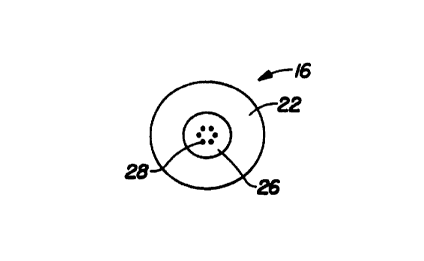
FIG. 1 is a top plan view of a powder conduit of the present invention,
showing
an annular flange and a plurality of apertures in an apertured member;
FIG. 2 is a side elevation view thereof, disclosing a flange, a sidewall of
the
mixing chamber, and a diptube supported from the bottom end of the chamber;
FIG. 3 is a top plan view of a squeezebottle dispenser containing the conduit,
disclosing a self seal slit valve for powder discharge;
FIG. 4 is a sectioned side elevation view thereof, taken along section line 4-
4 of
FIG. 3, showing the slit valve located atop the flange of the conduit and the
conduit
located within the squeezebottle, with a typical powder settled in the
squeezebottle after
an initial powder discharge;
FIG. 5 is a top plan view of the dispenser of FIG. 4, showing the sides of the
squeezebottle being squeezed and the slit valve being opened after a threshold
pressure
developed inside the bottle has been reached; and
FIG. 6 is a sectioned side elevation view similar to FIG. 4, showing the
location
of powder when the squeezebottle is squeezed to cause a discharge.
DETAILED DESCRIPTION OF THE INVENTION
Referring now to the drawings, and more particularly to FIGS. 1 - 4, there is
shown a preferred embodiment of the present invention, which provides a
squeezebottle
powder dispenser, and is generally indicated as 10. Dispenser 10 has a
resilient
container 12 and a discharge end 14. Mounted to discharge end 14 is a
substantially
rigid conduit, _which is generally indicated as I 6. As shown in FIGS. 2 and
4, conduit
16 has a fitment I8 at one end and a substantially squared-off diptube 20 at
the other
end. Fitment 18 is preferably shaped to press-fit into the finish of resilient
container 12.
Fitment 18 preferably has a flange which forms an outside end 22 of conduit
16.
Diptube 20 is preferably permanently connected to fitment 18, such as by
interference
fit, and it extends from frtment 18 to near an inside bottom surface 23 of
resilient
container 12 to form an inside end 24 of conduit 16.
FIGS. 1 and 4 show .fitment 18 having an apertured member 26, which is
preferably a rigid plate perpendicular to the axis of fitment 18. Apertured
member 26
CA 02269351 1999-04-20
WO 98/18565 PCT/US97/15848
6
has at least one aperture 28 therethrough, which has a cross-sectional area
less than that
of the inside of diptube 20. A plurality of apertures 28 similarly have a
combined cross-
sectional area less than that of the inside of diptube 20. The purpose of
apertured
member 26 and apertures) 28 is to increase the velocity of air flowing through
diptube
20 near discharge end 14 so that better mixing of air and powder occurs just
before
discharge. Apertured member 26 also forms a shelf upon which residual powder
from a
previous dispensing cycle may rest when container 12 is oriented upright. The
powder
on the shelf acts as a prime, such that when the container is f rst squeezed
and sufficient
air pressure is developed inside the container to lift powder through the
diptube, powder
is immediately ready for discharge. A second apertured member, such as a
screen,
which is not shown, may be located above apertured member 26 to further
increase
mixing and to act as an additional shelf.
FIGS. 3 and 4 show discharge end 14 of dispenser 10 having a resilient flat
member 30 covering outside end 22 of conduit 16. Resilient flat member 30 has
a short
slit 32 near the center of flat member 30. Flat member 30 is preferably made
of a thin
compliant material so that slit 32 opens under minimal pressure differential
developed
inside container 12. Slit 32 is preferably straight and shorter in length than
the inside
diameter of outside end 22 of conduit 16. Slit 32 serves as a discharge valve
for
dispenser I0. Slit 32 is normally closed and self seals container 12 from the
ambient
environment outside dispenser 10.
Flat member 30 is preferably held in place against outside end 22 by a
threaded
closure 34, which engages threads on the finish of container 12. Inside
threaded closure
34 may be placed a substantially rigid annular member 36 which clamps flat
member 30
against the inside of closure 34. Having annular member 36 inside closure 34
isolates
from flimsy flat member 30 the twisting and compression forces generated by
applying
closure 34 against outside end 22. Such isolation is beneficial so that flat
member 30 is
not distorted when closure 34 is installed. Closure 34 has an opening 38
centered
therein about the same size as an opening in annular member 36. Opening 38 is
sized so
that powder and air dispensed from slit 32 in a conical or fan-shaped pattern
have
clearance and are not restricted by the closure.
FIG. 4 shows a powder 40 and a volume of headspace air 42 above powder 40
inside container 12 and diptube 20. Powder 40 is also shown resting above
apertured
member 26. This is the condition of a powder dispenser of the present
invention after an
initial dispensing cycle and just before the next squeeze. After the initial
cycle, wherein
resilient sidewalls of container 12 are squeezed to dispense powder and air,
the sidewalls
are released. When the sidewails are released, they return to their original
shape and in
CA 02269351 1999-04-20
WO 98/18565 PCT/US97/15848
7
doing so draw a vacuum inside container 12. The vacuum is sufficient to open
slit 32 to
allow replacement air into container 12. Since the only path for air and
powder into and
out of container 12 is through conduit 16, air and powder are sucked back down
diptube
20. Thus, the level of powder shown in diptube 20 is usually different than
the level of
powder shown in the rest of container 12.
The space between apertured member 26 and flat member 30 forms a mixing
chamber 44 wherein a portion of powder 40 and a portion of volume of air 42
may mix
before being discharged through slit 32. Such mixing is beneficial in
providing a
consistent mixture during the discharge. That is, mixing avoids spurting of
clumps of
powder. Apertured member 26 is preferably nearer flat member 30 than inside
end 24 of
conduit 16.
FIGS. 5 and 6 show dispenser 10 in a condition in which the sidewalls of
container 12 are squeezed to cause powder 40 and air 42 to discharge. Air 42
from the
headspace above powder 40 is compressed by squeezing the container sidewalls
to
generate a differential pressure compared to ambient air outside dispenser 10.
Since the
only path for discharging air 40 is via diptube 20, air fluidizes a portion of
powder 40 as
it rushes to inside end 24 of conduit 16. Fluidized air and powder are than
lifted upward
in diptube 20 and through apertured member 26 into mixing chamber 44, from
which the
mixture discharges through slit 32. FIG. 5 shows squeeze force F applied to
the
sidewalls and slit 32 opened. FIG. 6 shows a conical or fan-shaped spray 46 of
powder
and air directed at a target surface 48 parallel to flat member 30. The
properties of
powder 40 and of target surface 48 enable the spray 46 to substantially remain
on target
surface 48, which is preferably the human body when powder 40 is a moisture
absorbing
powder. Because of the low threshold pressure differential necessary to open
slit 32,
minimal dust cloud of small particles is generated around spray 46.
In a most preferred embodiment of the present invention, dispenser 10 is
intended for dispensing a powder 40 having a packed bulk density ranging from
about
0.2 grams per. cubic centimeter to about 0.5 grams per cubic centimeter and an
aerated
bulk density ranging from about 0.1 grams per cubic centimeter to about 0.3
grams per
cubic centimeter. This powder has a particle size ranging from about 1 micron
to about
100 microns, and more preferably from about 1 micron to about 60 microns, and
most
preferably from about 1 micron to about 20 microns; an angle of repose ranging
from
about 40 degrees to about 50 degrees; an angle of fall ranging from about 20
degrees to
about 35 degrees; and an angle of difference ranging from about 15 degrees to
about 25
degrees. Powder characteristics are measured by using a Powder Characteristics
Tester
Model PT-N, made by Micron Powder Systems of Summit, NJ.
CA 02269351 1999-04-20
WO 98/18565 PCT/US97/15848
8
An example of a preferred powder is a mixture by weight of 37.7% low moisture
cornstarch, 20% calcium silicate, 5% fumed silica, IO% silica microspheres, 8%
magnesium carbonate, 5% dimethicone, 3% nylon N-12, 3% zinc stearate, 3% zinc
phenolsulphonate, 0.2% triclosan, 0.1 % Aloe Vera, 2% encapsulated tocopheryl
acetate,
and 3% beta cyclodextrin.
Resilient container 12 is preferably an oval, six fluid ounce capacity,
polyolefin
bottle, such as an Oil of Olay Beauty Fluid bottle, made by The Procter &
Gamble
Company of Cincinnati, OH. However, shape of the squeezebottle is not limited.
It
could be round or other shape, tall or short, as long as the deformation of
the bottle
produces sufficient air pressure differential to lift the powder through the
conduit and
open the slit valve. The range of powder dispensed per typical squeeze cycle
varies in a
full to empty dispenser from about 0.20 gm to about 0.02 gm. The preferred air
headspace when the container is "full" is about 20% of the bottle volume. The
lower the
percent headspace, the more likely the conduit is to plug upon repeated
squeezes.
Fitment I 8 is preferably molded of polypropylene, and is about 2.5 cm long
and
about 2.2 cm diameter at the flange, with an internal diameter of mixing
chamber 44
being about 12 mm. Mixing chamber 44 is preferably about I8 mm deep. Although
fitment 18 and diptube 20 could possibly be formed as a single part, different
sized
diptubes are useful if they are connected to the fitment by an adapter 50, as
shown in the
FIGS. 4 and 6. Different sized diptubes are beneficial when powder properties
are
changed. For example, a lighter density powder will function with a smaller
diameter
diptube without clogging, whereas a heavier density powder may require a
larger
diameter diptube. For the preferred powder, a diptube made of polypropylene
and
having an inner diameter of about 0.35 inches (8 mm) is preferred. Diptube 20
extends
about 9.7 cm from ftment 18 to within about 0.25 inches (6 mm) of the inside
bottom
surface of container 12. It is believed that these dimensions provide
sufficient air
velocity at the inside end of conduit 3 6 to lift a portion of powder 40
through the conduit
to the outside_ end 22 when the powder dispenser is operated in a
substantially upright
orientation. It is further believed that orientation of the dispenser from
horizontal to
near upright does not require as high an air velocity as does the upright
orientation. The
larger the conduit internal diameter, the greater the air displacement needed
with each
squeeze of the container in order to lift powder through the conduit. AIso,
the larger the
conduit outside diameter, the smaller the squeeze stroke available. Thus, an
optimum
conduit diameter depends upon container shape and size and powder properties.
The
ideal gap between the end of the diptube and the bottom inside surface of the
bottle will
also vary with diptube internal diameter.
__. ..._._ _ t_ _
CA 02269351 1999-04-20
WO 98118565 PCT/US97/15848
9
Apertured member 26 is conveniently located in conduit 16 by use of an adaptor
between the diptube and fitment. Adapter 50 is preferably molded of
polypropylene and
is sized to secure itself and the diptube into fitment 18 by interference fit.
Alternatively,
conduit 16 could be made of materials which could be snapped, adhesively
bonded, or
welded together, or fabricated from a single piece of material. Preferably
member 26
has six evenly spaced apertures 28 therein of about 1 mm diameter each. Member
26 is
about 0.5 mm thick where the apertures are located. Having apertured member 26
in
conduit 16 is beneficial for air and powder mixing and providing a prime, but
it is not
necessary for dispenser 10 to function. Having a constant diameter conduit 16
leading
to resilient flat member 30 is functional but not optimal for the preferred
powder.
A feature of the present invention is a mixing chamber having only one
entrance
for both powder and air. Both powder and air rise through the diptube and
apertured
member to the mixing chamber. This arrangement is preferred for the light
density
powders intended to be dispensed by the present invention. For heavier density
powders, such as those containing primarily talc, it has been found that
providing one or
more separate passages through the side of fitment 18, for a small portion of
headspace
air to flow into the mixing chamber, improves dispensing. Such passage or
passages
may be beneficial for dispensers intended to be used in an upside down
orientation in
order to provide a path other than the diptube for powder to flow into the
mixing
chamber. Dispensing of heavier density powders and upside down dispensing are
not
intended for the present invention, however, such operation may be facilitated
by the
addition of separate passages into the mixing chamber.
Resilient flat member 30 is made of approximately 0.030 inch thick silicone
rubber having a durometer of approximately 30 Shore A. Slit 32 is linear along
a
diameter of flat member 30 and has a length of approximately 0.25 inches or 6
mm, such
that a discharge spray 46 provides a substantially round powder pattern at
external target
surface 48, assuming the target surface is substantially parallel to the
resilient flat
member. Other lengths of slit, thicknesses of flat member, etc., may result in
other
useful spray patterns. With the preferred dimensions and material properties
of flat
member 30, the threshold pressure ranges from about 0.5 pounds per square inch
to
about 3 pounds per square inch, so that a burst of air and powder discharges
at a
sufficiently low velocity to avoid a substantial dust cloud of fine particles.
A threaded closure 34 is shown clamping flat member 30 to flanged outside end
22 of conduit 16. Alternative closures could be used or the flat member could
be formed
as an integral part of the fitment.
CA 02269351 1999-04-20
WO 98118565 PCT/US97/15848
While particular embodiments of the present invention have been illustrated
and
described, it will be obvious to those skilled in the art that various changes
and
modifications may be made without departing from the spirit and scope of the
invention,
and it is intended to cover in the appended claims all such modifications that
are within
the scope of the invention.