Note: Descriptions are shown in the official language in which they were submitted.
CA 02269366 1999-04-21
PFP:250 US
CONCAVE BAFFLE
Background of the Invention
This invention relates to baffles for use in containers used for mixing of
fluids,
especially where at least one of the fluids is a liquid.
The use of rotating mixers in containers, especially cylindrical tanks, in the
absence of some sort of baffle, results in a swirling motion of liquid within
the
container. Such swirling motion is generally laminar in nature, possessing
none of
the turbulent flow characteristics required for mixing low-viscosity fluids.
The
swirling motion also possesses very little vertical movement of the fluid
which is
necessary for effective mixing.
It is known that baffles, placed within the container, so as to disrupt the
swirling motion, creates a turbulence which greatly improves mixing
efficiency. Such
baffles are usually elongated flat plates placed so that their longitudinal
axis is parallel
to the tank wall and so that the width of the plate rests on a tank diameter.
The baffle
is usually slightly offset from the tank wall to prevent accumulation of
material at a
baffle-tank wall interface.
It has been generally believed that four, rectangular, side-wall mounted
baffles
are the most effective baffle system available. Such baffles are not, however,
suitable
for use in vessels which are lined with a corrosion resistant material, such
as glass,
plastic or some chemically resistant alloys, since they cannot be easily
attached to the
tank sidewall for support without creating a breach in the corrosion resistant
lining.
Further, the configuration of such rectangular baffles are not generally
suited for
1
CA 02269366 1999-04-21
lining with a corrosion resistant layer because of severe angles associated
with a four
sided plate.
It has been known to suspend corrosion resistant, e.g. glass lined, baffles,
either
from the top or bottom of a tank. Such baffles must thus be sized to fit
through an
access hole in the tank. Known baffles, including fin type baffles and
rectangular
baffles are not as efficient as desired for that purpose. Further rectangular
baffles are
not suitable for suspension, since the width of the baffle is restricted by
the size of the
access hole. Further for suspension proximate four sidewalls, four access
holes would
be needed.
Brief Description of the Drawin2s
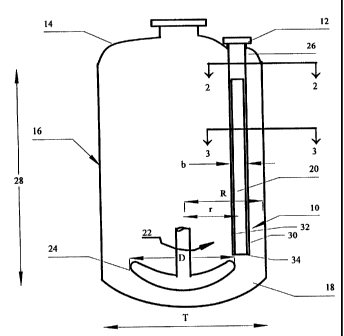
Figure 1 is a schematic cross sectional view of a tank containing a preferred
embodiment of a baffle of the invention.
Figure 2 is a cross section of an upper supporting portion of the baffle in
Figure
1 taken at line 2-2.
Figure 3 is a cross section of the baffle in Figure 1 taken at line 3-3
showing a
baffle formed by pressing a pipe into a concave cross section comprising
double
curvilinear surfaces.
Figure 4 is an alternative embodiment of a cross section of a baffle of the
invention showing a concave cross section formed by plates attached at an
angle "a".
Figure 5 is an alternative embodiment of a cross section of a baffle of the
invention formed by plates at an angle a attached to a hollow pipe.
Figure 6 is an alternative embodiment of a cross section of a baffle of the
invention formed by a plate pressed into an arcuate cross section.
2
CA 02269366 1999-04-21
Figure 7 is a bar graph showing the effect of baffles of various
configurations
upon normalized power number.
Brief Description of the Invention
In accordance with the invention, there is provided a new baffle design which
is more efficient than previous baffles for apparent surface area contact, and
especially
more efficient than those which could be inserted through an access opening in
an end
wall of a container. Further the new baffle is easy to manufacture and can be
easily
made in a configuration suitable for coating with a corrosion resistant
material,
especially glass.
More particularly the invention comprises a baffle for insertion into a
container. The baffle comprises a concave surface defined by two essentially
parallel
line segments connected to each other at their ends by line segments
subtending an
angle. The baffle further includes a means for mounting to a container so that
the line
segments are essentially parallel to and offset from a side wall of the
container.
Preferably, the means for mounting is a means for suspending said baffle from
a first end wall of said container without attachment to a container side
wall. The
concave surface is preferably a curvilinear concave surface and the contiguous
line
segments subtending an angle are in the form of an arc.
In a preferred embodiment, chords joining ends of each arc are less than one-
fourth of a length of a diameter of the container and more preferably from
about 9 to
about 13 percent of the diameter of the container.
The baffle is desirably sized to pass through as opening in a first endwall of
the
container, which opening is less than one-fourth of the diameter of the
container.
3
CA 02269366 1999-04-21
Detailed Description of the Invention
"Baffle" as used herein means a surface used to disrupt liquid flow in a
container provided with a rotating agitation means. Such a baffle has a length
(sides)
and a width (ends) defining the surface and is usually mounted in a container
so that
the length is oriented in the same direction as a length of the container.
"Container" means essentially any container which can hold liquid and a
rotating agitation means. The container may be defined by a single sidewall,
as when
the sidewall is circular in shape to form a cylinder or may be defined by a
plurality of
sidewalls to form a polygonal cross section. The containers usually have
either a
circular cross section with a single curved sidewall or rectangular cross
section with
four adjoining sidewalls. Such containers are usually tanks having a circular
cross
section. The main body of the tank is usually cylindrical.
"Concave surface" means a surface having a depressed central portion. In
general the concave surface is defined by two essentially parallel line
segments
connected to each other at their ends by contiguous line segments subtending
an angle.
The parallel lines and line segments define the surface of the baffle. The
parallel lines
are oriented along the length of the baffle. Curved lines, connecting the
parallel line
segments, may be considered as an infinite number of contiguous line segments.
Such
concave surfaces may be in many forms, e.g. a surface formed by two plates
intersecting at an angle or surface formed by a plate in the form of a
semiellipse,
parabola or hyperbola. The "apparent surface area" of the baffle is an area
defined by
the length of the baffle times the length of a chord joining ends of the
parallel line
segments. The chord may also be referred to as the "projected width".
4
CA 02269366 1999-04-21
The means for mounting in accordance with the invention may be supports
mounted to the baffle along its length and to a sidewall of the container, but
in
accordance with the invention is usually a support mounted at an end of the
baffle for
suspending the baffle from an end wall of the container without mounting to a
sidewall of the container. Such an end support may, for example, be an
attachment by
bolts or welding to a cover which attaches to a flange surrounding an access
hole in
the top wall of a container. In such a case the access hole is usually less
than one-
fourth of the diameter of the container and the baffle is sized to pass
through it.
Preferably, the baffle of the invention is coated with a corrosion resistant
material. Such materials may be plastics, ceramics, glass and corrosion
resistant metal
alloys. The preferred corrosion resistant coating is glass. "Glass" as used
herein
means any contiguous inorganic surface formed by fusion of water insoluble
inorganic
materials. Such glasses are usually amorphous and are formed by fusion of
glass frit.
Examples of such glasses are various silicate glasses. In order to permit
"glassing",
the baffle of the invention usually has rounded corners and edges. Such a
baffle
having curved edges is readily formed by pressing a tube or pipe, having
opposed
convexly curved sides, in a die to cause one side (one-half) of the tube or
pipe to
conform essentially to the curve of the other half of the tube or pipe to form
a concave
surface. In such a case, the baffle takes the form of a double curvilinear
surface
attached at the location of the parallel line segments.
The concave baffles of the invention may be considered to be a specific form
of
insertable baffles suitable for use in glass-lined mixing vessels. Such
inserted
baffles, in a preferred arrangement, is located at a radius (r) which is 72-
82% of the
5
CA 02269366 1999-04-21
full vessel radius (R), with a projected width (b) which is 9-13% of the
vessel
diameter (T), and an overall length which allows it to range over the vessel
straightside length 28 as shown in Figure 1. Optionally more than one such
insert
baffle may be used.
As shown in Figure 1, a baffle 10 in accordance with the invention defined by
parallel line segments 30, 32 and contiguous line segments 34 subtending an
angle
(Figures 3-6), may be supported from a nozzle opening 12 in either the top
head 14 or
bottom head 18 of a mixing vessel 16. Such a top head support is shown in
Figure 1.
The baffle also may be mounted from an opening in a sidewall of the vessel;
although,
such a configuration is not typical. The baffle is oriented so that concave
portion 20 of
baffle 10 faces the direction of flow 22 produced by a rotating impeller 24
such as
typically used in a mixing vessel. In this orientation, concave baffle 10 of
the
invention thoroughly interrupts ineffective swirling flow and converts it into
an
effective three dimensional turbulent flow.
In the preferred embodiment of the invention shown in Figure 1, baffle 10
supported from nozzle 12 of top 14 of vessel 16 has a semicircular cross
section as
shown in Figure 3. This cross section is preferably a semicircle with a total
arc of
about 180 degrees. This profile has a desirably high drag coefficient of about
2.3.
This is significantly higher than the drag coefficients for known cross
sections used
for inserted baffles and is higher than flat baffles when they are used in the
same
numbers as inserted baffles. The top end 26 of baffle 10 may have a circular
cross
section for ease of support. The baffle may have other concave cross sections,
e.g. as
6
CA 02269366 1999-04-21
shown in Figures 4, 5 and 6. The other concave cross sections in accordance
with the
invention also have high drag coefficients.
The concave baffle of the invention offers significant improvement in baffle
effectiveness over other inserted baffle designs because it can interrupt
swirling flow
induced by an impeller to a greater degree with the same number of baffle
elements
and the same projected width.
Baffle effectiveness is indicated by the characteristic power number of an
impeller system used in conjunction with a given baffle system. For a given
impeller
type with a span (D) operating at a speed (N) in a full vessel, the power
number of the
impeller will be a function of Reynolds number (i.e. flow regime) and baffle
type.
When four sidewall baffles are used, a vessel is assumed to be fully baffled
with a
maximum power number. When fewer than four inserted baffles are used (the
usual
case), the power number at a given Reynolds number is reduced. The more
effective
the baffle, the less the reduction in the power number. A comparison of baffle
effectiveness is shown in Figure 7 where one and two concave baffles of the
invention
are compared with full baffling (4 standard baffles), one and two standard
(i.e., wall-
mounted) baffles, and one and two fin baffles which were considered the most
effective insert type baffle until the present invention. In Figure 7, CBT
means
"Curved Blade Turbine" (an impeller commonly used in glass-lined mixing
vessels);
Re> 100,000 defines the range of Reynolds number (Re) for the data shown, and
indicates the flow to be fully turbulent; and Np means "Normalized Power
Number",
with all values referenced to the Power Number for a fully baffled (4 standard
baffles)
case.
7
CA 02269366 1999-04-21
Figure 7 clearly shows that the concave baffles of the present invention are
more efficient than an equal number of standard wall-mounted or traditional
fin type
baffles and are almost as effective as four standard flat baffles when only
two concave
baffles are used.
8