Note: Descriptions are shown in the official language in which they were submitted.
CA 02269534 1999-04-21
Method for the Three-Dimensional Movement of the Projection
Beam of a Video or Graphics Projector
This invention relates to a method for the three-dimensional
movement of the projection beam of a video or graphics pro-
jector, wherein the projection beam coming from a light
source and guided over and/or through an optoelectronic image
generator and through a projection lens is deflected by means
of at least one mirror to be swivelled about two axes, an X-
axis extending in direction of incidence of the projection
beam and a transversely extending Y-axis.
Video or graphics projectors, which provide for the projec-
. tion of video images or computer graphics, have so far mostly
been used for a still projection onto a given projection sur-
face by means of a projection beam fixedly aligned with re-
spect to this projection surface, so that these projections
are bound to firmly preadjusted image positions. The applica-
tion of video and graphics projections for show, advertising
and simulation purposes, however, requires a three-
dimensional movement of the projection beam and thus a fast
movability of the precisely positionable projection beam, for
which purpose it would basically be possible to support the
projector in a swivel-mounted revolving shackle, which leads,
however, only to a slow, low-power motional projection im-
paired by vibrations.
In order to achieve fast light effects and good projections
moving in three dimensions, it has also already been proposed
CA 02269534 1999-04-21
- 2 -
to deflect the projection beam behind the projection lens by
means of a swivel-mounted mirror, but when swivelling the
mirror about an axis of rotation extending in direction of
incidence of the projection beam, a fundamental imaging prob-
lem arises, as the projection image also rotates in depend-
ence on the position of the mirror, until it is upside down
after a rotation of the mirror by 180°. To correct this aber-
ration, the projection beam is rotated about the beam axis
behind the image generator by means of mirrors or optical
prisms in accordance with WO 94/08425 or US 4,235,535, so as
to be able to project the projected image without aberra-
tions. However, optically influencing the projection beam in
this way requires a considerable constructional effort, re-
quires a corresponding construction space, increases the
light losses during the projection, and involves additional
sources for optical defects, which lead to an impairment of
the production quality.
It is therefore the object underlying the invention to pro-
vide a method as described above, which in an economic and
inexpensive way provides for extremely fast motional projec-
tions with a perfect compensation of the aberrations result-
ing from the rotation of the mirror, and in addition offers
the possibility for further influencing the images to be pro-
jected.
This object is solved by the invention in that when the mir-
ror is swivelled about the X-axis, the images to be pro-
jected, which were produced by the image generator, are addi-
tionally rotated in a forced coupling with the swivel move-
ment of the mirror, in order to compensate the occurring ab-
erration. By means of this both simple and elegant measure
the image to be projected is itself influenced in the sense
of a compensation of defects, and to compensate an aberration
resulting from the swivelling of the mirror, it is tracked
with a fixed angle with respect to this swivel movement. In
CA 02269534 1999-04-21
- 3 -
this way, special optical means for influencing the already
image-bearing projection beam are avoided, and optimum pro-
jection qualities are ensured with relatively little con-
structional effort and space requirement.
A particularly advantageous possibility for an additional ro-
tation of the image is obtained when the images of the image
generator are rotated by means of a digital special-effects
processor with a function "rotation normal to the image
plane", which activates the image generator. This processor
known per se in video technology or from GB 22 65 064 A of-
fers a simple means for activating the optoelectronic image
generator corresponding to the specific functions of the
processor and, by means of the function "rotation normal to
the image plane", for producing the image of the image gen-
erator already in the rotary position required for image cor-
rection. For the image generator, every technology suitable
for video or graphics projections may be used, for instance
LCD (Liquid Crystal Display), DMD (Digital Micromirror De-
vice), CRT (Cathode Ray Tube), ILA (Image Light Amplifier),
Light-Valve Technology and the like, as the processor influ-
ences the image signals activating the image generator and
need therefore not interfere in the actual function of the
image generator.
When a special-effects processor is associated to the image
generator, the images of the image generator can additionally
be influenced or changed by means of this processor with re-
spect to brightness, dimensioning, magnification, masking,
colour adjustment, rectifications or the like, which corre-
spondingly widens the applications and possibilities of a mo-
tional projection and in addition to the correction of aber-
rations also provides for an adjustment of the image impres-
sion, the image size, the image format, and the like. The im-
age can thus for instance also be covered (masked) or reduced
such that by rotating the image the frame of the image gen-
CA 02269534 1999-04-21
- 4 -
erator is not crossed, and the entire image can also be pro-
jected in a rotated position. Without an additional effort,
all functions of the processor can thus also be utilized for
the motional projection.
A further possibility for an additional rotation of the image
is obtained in that an image carrier for the images to be
projected, which were produced by the image generator, is ro-
tated itself for additionally rotating the images. Such image
carrier, on which the image to be projected is formed, need
merely be rotated about the X-axis by means of an electrome-
chanical rotating mechanism in a forced coupling with the ro-
tation of the mirror, which in turn leads to a perfect com-
pensation of the aberration resulting from the rotation.
When there is provided an image generator in accordance with
the DMD technology of Texas Instruments, whose image carrier
accommodates a plurality of tiltable mirror elements, the im-
age carrier is rotated about an axis of rotation normal to
the respective image-effective mirror elements, so that de-
spite the tilted position of the activated mirror elements
the image to be projected is also formed in a rotated posi-
tion. In accordance with the DMD technology, the mirror ele-
ments associated to each image point are tilted by activating
the same such that the projection beam is directed through
these mirror elements to the projection lens. The non-
activated, image-ineffective mirror elements remain tilted in
opposite directions, so that the impinging light beams are
deflected to a light absorber beside the projection lens and
provide no image points. So as not to endanger this image-
forming reflection principle by a rotary adjustment, the axis
of rotation of the image carrier accommodating the mirror
elements must be moved about an axis of rotation normal to
the image-effective mirror elements. In addition, the ab-
sorber for the deflected image-ineffective light beams must
CA 02269534 1999-04-21
- 5 -
likewise be rotated or have a correspondingly ring-shaped de-
sign.
In accordance with a particularly advantageous aspect of the
invention, the special-effects processor associated to the
image generator is activated via a control assembly, which at
the same time activates the swivel drives of the mirror, ad-
justing means of the projection lens, control means of the
light source, and possibly the rotary drive for the image
carrier. The projector can thus be activated by means of the
control assembly not only with respect to the correction of
aberrations, but also with respect to actual projector func-
tions, so that by means of this control assembly the mirror
rotations, the focussing of the projection lens, the zoom
function of this lens, the brightness of the light source or
the projection beam, the various functions of the processor
itself and the like can be controlled and adjusted.
By means of such a control assembly it is then possible to
provide for the activation of the control assembly itself via
an external control device, preferably in accordance with a
predeterminable program, which for instance allows for an ac-
tivation of this control device via a lighting control desk
of a stage, so that the video or graphics projector can be
used and operated similar to a spotlight in connection with a
complex lighting program.
In the drawing, the subject-matter of the invention is repre-
sented by way of example, wherein:
Fig. 1 is a schematical representation of a video projector
for performing the inventive method, and
Fig. 2 is a block circuit diagram of the control structure
of this projector.
CA 02269534 1999-04-21
- 6 -
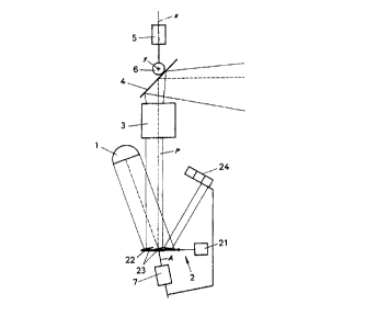
During the motional projection of video images or computer
graphics, a projection beam P processed by reflectors and
lenses not represented in detail is guided from a light
source 1 over an optoelectronic image generator 2 and through
a projection lens 3, behind which a mirror 4 with two elec-
tromechanical rotating mechanisms 5, 6 for rotating the mir-
ror about an X-axis extending in direction of incidence of
the projection beam and about a transversely extending Y-axis
is provided for the three-dimensional movement of the projec-
tion beam, from which mirror 4 the image-bearing projection
beam then impinges on not represented screens, objects, per-
sons or any other media, corresponding to the deflection. For
the purpose of image formation, the image generator 2 oper-
ates according to the DMD technology of Texas Instruments and
comprises on the one hand an image signal generator 21 and an
image carrier 22, which image carrier 22 has a plurality of
tiltable mirror elements 23, which are activated by means of
the image signal generator 21 in dependence on the images to
be projected such that the image-effective mirror elements 23
reflect the incident light beams of the projection beam to-
wards the projection lens 3, whereas the ineffective mirror
elements direct the light beams towards a light absorber 24.
In order to correct the aberrations resulting from swivelling
the mirror 4 about the X-axis, the image carrier 22 of the
image generator 2 is additionally rotated under a fixed angle
together with the swivel movement of the mirror 4, where the
image carrier 22 is rotated by means of a rotating mechanism
7 about an axis of rotation A normal to the effective mirror
elements 23, so as not to impair the image-forming effect of
the mirror elements. The light absorber 24 is also rotated,
so as to intercept the image-ineffective light beams inde-
pendent of the rotary position of the image carrier 22.
As is illustrated in Fig. 2, the control structure for the
motional projection comprises a special-effects processor 8
CA 02269534 1999-04-21
-
associated to the image generator 2 and a control assembly 9,
where the processor 8 is activated on the one hand by image
signals B of a video apparatus or a computer for forming the
images to be projected, and on the other hand by the control
assembly 9 with respect to the functions of the processor 8,
such as rotation of the image signal D, masking of the image
signal M, zooming of the image signal Z, brightness of the
image signal H, colour surface signals F, angle signal in de-
pendence on the rotary position W of the mirror and keystone
rectification of the image signal T. According to these pa-
rameters, the processor 8 itself influences the image genera-
tor 2, which produces a corresponding image on the image car-
rier 22. Along with the activation of the processor 8 and in
dependence on control signals S provided by an external con-
trol device not represented in detail, the control assembly 9
additionally activates via control lines V, O, E, L, N the
rotating mechanisms 5, 6 of the mirror 4 for rotating the
same about the X-axis and the Y-axis, the adjusting means of
the projection lens 3 for focussing and for optically zooming
the projection image, the light source 1 for influencing the
brightness, and possibly the rotating mechanism 7 for addi-
tionally rotating the image carrier 22 corresponding to the
X-adjustment of the mirror 4.