Language selection

Search

Patent 2269787 Summary

Third-party information liability

Some of the information on this Web page has been provided by external sources. The Government of Canada is not responsible for the accuracy, reliability or currency of the information supplied by external sources. Users wishing to rely upon this information should consult directly with the source of the information. Content provided by external sources is not subject to official languages, privacy and accessibility requirements.

Claims and Abstract availability

Any discrepancies in the text and image of the Claims and Abstract are due to differing posting times. Text of the Claims and Abstract are posted:

  • At the time the application is open to public inspection;
  • At the time of issue of the patent (grant).
(12) Patent: (11) CA 2269787
(54) English Title: VISUAL TIRE CAP PRESSURE GAUGE
(54) French Title: BOUCHON CONTROLEUR DE PRESSION D'UN PNEU A LECTURE DIRECTE
Status: Expired and beyond the Period of Reversal
Bibliographic Data
(51) International Patent Classification (IPC):
  • B60C 23/02 (2006.01)
(72) Inventors :
  • CUMMINGS, CRAIG (United States of America)
(73) Owners :
  • CRAIG CUMMINGS
(71) Applicants :
  • CRAIG CUMMINGS (United States of America)
(74) Agent: OSLER, HOSKIN & HARCOURT LLP
(74) Associate agent:
(45) Issued: 2002-07-16
(86) PCT Filing Date: 1996-10-28
(87) Open to Public Inspection: 1998-05-07
Examination requested: 1999-04-23
Availability of licence: N/A
Dedicated to the Public: N/A
(25) Language of filing: English

Patent Cooperation Treaty (PCT): Yes
(86) PCT Filing Number: PCT/US1996/017266
(87) International Publication Number: US1996017266
(85) National Entry: 1999-04-23

(30) Application Priority Data: None

Abstracts

English Abstract


A visual tire cap pressure gauge (10) which comprises a cap member (12). A
structure within the cap member (12) is for securing the cap member to a valve
stem (16) on a tire (18) in a motor vehicle (20). A lens (22) is mounted in a
top end of the cap member (12). An assembly (24) within the cap is for
visually indicating when air pressure within the tire (18) drops below a set
point, so as to enable a person at a glance to tell if the tire needs more air.


French Abstract

Un bouchon contrôleur de pression d'un pneu à lecture directe (10) comprend un capuchon (12). Une structure à l'intérieur du capuchon (12) sert à fixer le capuchon sur une tige de soupape (16) d'un pneu (18) de véhicule à moteur (20). Une lentille (22) est monté sur une extrémité supérieure du capuchon (12). Un système (24) à l'intérieur du bouchon affiche directement le niveau de pression d'air dans le pneu (18) lorsque ce niveau descend au-dessous d'un point donné, ce qui permet à une personne d'apprécier d'un coup d'oeil si le pneu nécessite plus d'air.

Claims

Note: Claims are shown in the official language in which they were submitted.

13
VISUAL TIRE CAP PRESSURE GAUGE
CLAIM
1. A sealed visual tire cap pressure gauge which comprises:
a) a cap member consisting of a cylindrical hollow housing having an
open top end and an open bottom end;
b) means within said cap member comprising internal threads located
within the open bottom thereof for engaging the threaded portion of the
valve stem, for securing said cap member to a valve stem on a tire in a motor
vehicle;
c) a disc-shaped transparent lens sealed and mounted in the top end of
said cap member to allow the person to look through said cover into said
cylindrical hollow housing; and
d) means within said cap member for visually indicating when air
pressure within the tire drops below a set point, so as to enable a person at
a
glance to tell if the tire needs more air, said visually indicating means
comprising a diaphragm mounted within said cylindrical housing dividing
said cylindrical hollow housing into a lower chamber and an upper chamber,
a valve depressor rod extending down from a bottom surface of said
diaphragm into said lower chamber to make contact with the valve stem to
release the pressurized air from the tire into said lower chamber to deflect

14
said diaphragm upwardly into said upper chamber when the air pressure is at
the set point, a bright colored fluid within said upper chamber which can be
readily seen through said lens, a plurality of rods extending upwardly from a
top surface of said diaphragm into said upper chamber, a dark colored plate
affixed to the top ends of said rods within said upper chamber and below the
underside of said lens, and spring means comprising a coil spring between
said dark colored plate and said lens in said upper chamber to normally bias
said dark colored plate downwardly away from said lens, so that in a first
instance when the air pressure is at the set point said dark colored plate
will
move up towards said lens and be viewed by the person when said
diaphragm deflects upwardly, and in a second instance when the air pressure
in the tire is below the set point, said coil spring pushing said dark colored
plate away from said lens allowing the person to view the bright colored
fluid within said upper chamber indicating that the air pressure in the tire
has dropped below the set point.

Description

Note: Descriptions are shown in the official language in which they were submitted.


CA 02269787 1999-04-23
WO 98/18639 PCT/US96/17266
VISUAL TIRE CAP PRESSURE GAUGE
Des~ption
Technical Field
The instant invention relates generally to pressure indicating devices
and more specifically it relates to a visual tire cap pressure gauge.
Disclosure of the Invention
_ A primary object of the present invention is to provide a visual tire cap
pressure gauge that will overcome the shortcomings of the prior art devices.
Another object is to provide a visual tire cap pressure gauge that is
threaded onto a valve stem which will automatically change color when a
tire looses a sufficient amount of air pressure, so that it would enable a
person at a glance to tell if the tire needs air.

CA 02269787 1999-04-23
WO 98/18639 PCT/US96/17266
2
An additional object is to provide a visual tire cap pressure gauge that
could be used for passenger, as well as commercial vehicles, and would be an
early warning system devised to save fuel, as well as possibly saving lives.
A further object is to provide a visual tire cap pressure gauge that is
simple and easy to use.
A still further object is to provide a visual tire cap pressure gauge that
is economical in cost to manufacture.
Further objects of the invention will appear as the description
proceeds.

CA 02269787 1999-04-23
WO 98/18639 PCT/IJS96/17266
3
Various other objects, features and attendant advantages of the present
invention will become more fully appreciated as the same becomes better
understood when considered in conjunction with the accompanying
drawings, in which like reference characters designate the same or similar
parts throughout the several views, and wherein;
FIGURE 1 is a perspective view of a motor vehicle, showing the instant
invention installed and in use.
FIGURE 2 is an enlarged perspective view as indicated by arrow 2 in
Figure 1, showing the instant invention mounted on a valve stem.
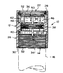
FIGURE 3 is a cross sectional view taken along line 3-3 in Figure 2.
FIGURE 4 is a top view taken in the direction of arrow 4 in Figure 2,
showing visually the tire pressure below a set point.

CA 02269787 1999-04-23
WO 98/18639 PCT/US96/17266
4
FIGURE 5 is a top view similar to Figure 4, showing visually the tire
pressure at the set point or above.
Similar reference characters denote corresponding features consistently
throughout the attached drawings.

CA 02269787 1999-04-23
WO 9S/18639 PCT/ITS96/17266
List of Reference Numbers in the Drawing Figure
visual tire cap pressure gauge
12 cap member of 10
14 securing structure in 12
16 valve stem on 18
18 tire in 20
motor vehicle
22 lens in 12
24 visually indicating assembly

CA 02269787 1999-04-23
WO 98/18639 PCT/US96/17266
6
26 cylindrical hollow housing of 12
28 open top end of 26
30 open bottom end of 26
32 internal threads in 30
34 threaded portion of 16
36 transparent disc-shaped cover for 22
38 diaphragm in 26
40 lower chamber of 26
42 upper chamber of 26

CA 02269787 1999-04-23
WO 98/18639 PCT/US96/17266
7
44 valve depressor rod on 38
46 bright colored fluid in 42
48 rod on 38
50 dark colored plate on 48
52 coil spring in 42

CA 02269787 1999-04-23
WO 98/18639 PCT/US96/17266
8
Detailed Description of the Preferred Embodiment
Turning now descriptively to the drawings, in which similar reference
characters denote similar elements throughout the several views, Figures 1
through 5 illustrate a visual tire cap pressure gauge 10, which comprises a
cap
member 12. A structure 14 within the cap member 12 is for securing the cap
member 12 to a valve stem 16 on a tire 18 in a motor vehicle 20. A lens 22 is
mounted in a top end of the cap member 12. An assembly 24 within the cap
member 12 is for visually indicating when air pressure within the tire 18
drops below a set point, so as to enable a person at a glance to tell if the
tire 18
needs more air.
The cap member 12 is a cylindrical hollow housing 26 ha~~ing an open
top end 28 and an open bottom end 30. The securing structure is internal
threads 32 located within the open bottom end 30 of the cylindrical hollow
housing 26 which can thread onto a threaded portion 34 of the valve stem 16.
The lens 22 is a transparent disc-shaped cover 36 sealed within the open top
end 28 of the cylindrical hollow housing 26, to allow the person to look
through the cover 36 and into the cylindrical hollow housing 26.

CA 02269787 1999-04-23
WO 98/18639 PCT/US96/17266
9
The visual indicating assembly 24 includes a diaphragm 38 mounted
within the cylindrical hollow housing 26, so as to divide the cylindrical
hollow housing 26 into a lower chamber 40 and an upper chamber 42. A
valve depressor rod 44 extends downwardly from a bottom surface of the
diaphragm 38 into the lower chamber 40. The rod 44 will make contact with
the valve stem 16 and release the pressurized air from the tire 18 into the
lower chamber 40, so as to deflect the diaphragm 38 upwardly into the upper
chamber 42 when the air pressure is at the set point.
A bright colored fluid 46 is carried within the upper chamber 42 which
can be readily seen through the lens 22. A plurality of rods 48 extend
upwardly from a top surface of the diaphragm 38 into the upper chamber 42.
A dark colored plate 50 is affixed to top ends of the rods 48, slightly below
the
lens 22 in the upper chamber 42.
A coil spring 52 is between the dark colored plate 50 and the lens 22 in
the upper chamber 42, to normally bias the dark colored plate 50 downwardly
away from the lens 22. In a first instance, as shown in Figure 5, when the air
pressure in the tire 18 is at the set point, the dark colored plate 50 will
move
up towards the lens 22 and be viewed by the person when the diaphragm 38
deflects upwardly.

CA 02269787 1999-04-23
WO 98/18639 PCT/US96/17266
In a second instance, as shown in Figures 3 and 4, when the air
pressure in the tire 1$ is below the set point, the coil spring 52 will push
the
dark colored plate 50 away from the lens 22 allowing the person to view the
bright colored fluid 46 within the upper chamber 42, thereby indicating that
the air pressure in the tire 18 has dropped below the set point.

CA 02269787 1999-04-23
WO 98/18639 PCT/US96/17266
11
Oyeration of the Inventign
To use the visual tire cap pressure gauge 10, the following steps should
be taken:
1. Screw the cap member 12 onto the valve stem 16, so that the
internal threads 32 located within the open bottom end 30 of the cylindrical
hollow housing 2b will thread onto the threaded portion 34 of the valve stem
16.
2. Make sure that the valve depressor rod 44 makes contact with the
valve stem 16, to release the pressurized air from the tire 18.
3. The diaphragm 38 will deflect upwardly into the upper chamber 42
when the air pressure is at the set point, thereby cause the dark colored
plate
50 to move up towards the lens 22 and be viewed by the person.
4. The diaphragm 38 will not deflect upwardly into the upper chamber
42 when the air pressure is below the set point, thereby causing the dark
colored plate 50 to move away from the lens 22 by the help of the coil spring
52.

CA 02269787 1999-04-23
Vu0 98/18639 PCT/U896/17266
12
5. The bright colored fluid can now be seen through the lens 22 by the
person to visually indicate that the tire 18 needs more air.

Representative Drawing
A single figure which represents the drawing illustrating the invention.
Administrative Status

2024-08-01:As part of the Next Generation Patents (NGP) transition, the Canadian Patents Database (CPD) now contains a more detailed Event History, which replicates the Event Log of our new back-office solution.

Please note that "Inactive:" events refers to events no longer in use in our new back-office solution.

For a clearer understanding of the status of the application/patent presented on this page, the site Disclaimer , as well as the definitions for Patent , Event History , Maintenance Fee  and Payment History  should be consulted.

Event History

Description Date
Inactive: Agents merged 2013-10-24
Time Limit for Reversal Expired 2003-10-28
Letter Sent 2002-10-28
Grant by Issuance 2002-07-16
Inactive: Cover page published 2002-07-15
Inactive: Final fee received 2002-05-02
Pre-grant 2002-05-02
Notice of Allowance is Issued 2001-11-13
Letter Sent 2001-11-13
Inactive: Approved for allowance (AFA) 2001-10-30
Inactive: Cover page published 1999-07-22
Inactive: First IPC assigned 1999-06-10
Inactive: Acknowledgment of national entry - RFE 1999-05-27
Application Received - PCT 1999-05-25
All Requirements for Examination Determined Compliant 1999-04-23
Request for Examination Requirements Determined Compliant 1999-04-23
Application Published (Open to Public Inspection) 1998-05-07

Abandonment History

There is no abandonment history.

Maintenance Fee

The last payment was received on 2001-10-22

Note : If the full payment has not been received on or before the date indicated, a further fee may be required which may be one of the following

  • the reinstatement fee;
  • the late payment fee; or
  • additional fee to reverse deemed expiry.

Patent fees are adjusted on the 1st of January every year. The amounts above are the current amounts if received by December 31 of the current year.
Please refer to the CIPO Patent Fees web page to see all current fee amounts.

Fee History

Fee Type Anniversary Year Due Date Paid Date
Request for examination - small 1999-04-23
Basic national fee - small 1999-04-23
MF (application, 2nd anniv.) - small 02 1998-10-28 1999-04-23
MF (application, 3rd anniv.) - small 03 1999-10-28 1999-09-15
MF (application, 4th anniv.) - small 04 2000-10-30 2000-10-20
MF (application, 5th anniv.) - small 05 2001-10-29 2001-10-22
Final fee - small 2002-05-02
Owners on Record

Note: Records showing the ownership history in alphabetical order.

Current Owners on Record
CRAIG CUMMINGS
Past Owners on Record
None
Past Owners that do not appear in the "Owners on Record" listing will appear in other documentation within the application.
Documents

To view selected files, please enter reCAPTCHA code :


To view images, click a link in the Document Description column. To download the documents, select one or more checkboxes in the first column and then click the "Download Selected in PDF format (Zip Archive)" or the "Download Selected as Single PDF" button.

List of published and non-published patent-specific documents on the CPD .

If you have any difficulty accessing content, you can call the Client Service Centre at 1-866-997-1936 or send them an e-mail at CIPO Client Service Centre.


Document
Description 
Date
(yyyy-mm-dd) 
Number of pages   Size of Image (KB) 
Abstract 1999-04-22 1 60
Description 1999-04-22 12 198
Drawings 1999-04-22 2 87
Claims 1999-04-22 2 64
Representative drawing 2001-10-30 1 13
Representative drawing 1999-07-15 1 19
Notice of National Entry 1999-05-26 1 202
Commissioner's Notice - Application Found Allowable 2001-11-12 1 166
Maintenance Fee Notice 2002-11-24 1 173
Correspondence 2002-05-01 1 60
Fees 2001-10-21 2 59
PCT 1999-04-22 7 297
Fees 1999-09-14 1 59
Fees 2000-10-19 1 57