Sélection de la langue

Search

Sommaire du brevet 2269787 

Énoncé de désistement de responsabilité concernant l'information provenant de tiers

Une partie des informations de ce site Web a été fournie par des sources externes. Le gouvernement du Canada n'assume aucune responsabilité concernant la précision, l'actualité ou la fiabilité des informations fournies par les sources externes. Les utilisateurs qui désirent employer cette information devraient consulter directement la source des informations. Le contenu fourni par les sources externes n'est pas assujetti aux exigences sur les langues officielles, la protection des renseignements personnels et l'accessibilité.

Disponibilité de l'Abrégé et des Revendications

L'apparition de différences dans le texte et l'image des Revendications et de l'Abrégé dépend du moment auquel le document est publié. Les textes des Revendications et de l'Abrégé sont affichés :

  • lorsque la demande peut être examinée par le public;
  • lorsque le brevet est émis (délivrance).
(12) Brevet: (11) CA 2269787
(54) Titre français: BOUCHON CONTROLEUR DE PRESSION D'UN PNEU A LECTURE DIRECTE
(54) Titre anglais: VISUAL TIRE CAP PRESSURE GAUGE
Statut: Périmé et au-delà du délai pour l’annulation
Données bibliographiques
Abrégés

Abrégé français

Un bouchon contrôleur de pression d'un pneu à lecture directe (10) comprend un capuchon (12). Une structure à l'intérieur du capuchon (12) sert à fixer le capuchon sur une tige de soupape (16) d'un pneu (18) de véhicule à moteur (20). Une lentille (22) est monté sur une extrémité supérieure du capuchon (12). Un système (24) à l'intérieur du bouchon affiche directement le niveau de pression d'air dans le pneu (18) lorsque ce niveau descend au-dessous d'un point donné, ce qui permet à une personne d'apprécier d'un coup d'oeil si le pneu nécessite plus d'air.


Abrégé anglais


A visual tire cap pressure gauge (10) which comprises a cap member (12). A
structure within the cap member (12) is for securing the cap member to a valve
stem (16) on a tire (18) in a motor vehicle (20). A lens (22) is mounted in a
top end of the cap member (12). An assembly (24) within the cap is for
visually indicating when air pressure within the tire (18) drops below a set
point, so as to enable a person at a glance to tell if the tire needs more air.

Revendications

Note : Les revendications sont présentées dans la langue officielle dans laquelle elles ont été soumises.


13
VISUAL TIRE CAP PRESSURE GAUGE
CLAIM
1. A sealed visual tire cap pressure gauge which comprises:
a) a cap member consisting of a cylindrical hollow housing having an
open top end and an open bottom end;
b) means within said cap member comprising internal threads located
within the open bottom thereof for engaging the threaded portion of the
valve stem, for securing said cap member to a valve stem on a tire in a motor
vehicle;
c) a disc-shaped transparent lens sealed and mounted in the top end of
said cap member to allow the person to look through said cover into said
cylindrical hollow housing; and
d) means within said cap member for visually indicating when air
pressure within the tire drops below a set point, so as to enable a person at
a
glance to tell if the tire needs more air, said visually indicating means
comprising a diaphragm mounted within said cylindrical housing dividing
said cylindrical hollow housing into a lower chamber and an upper chamber,
a valve depressor rod extending down from a bottom surface of said
diaphragm into said lower chamber to make contact with the valve stem to
release the pressurized air from the tire into said lower chamber to deflect

14
said diaphragm upwardly into said upper chamber when the air pressure is at
the set point, a bright colored fluid within said upper chamber which can be
readily seen through said lens, a plurality of rods extending upwardly from a
top surface of said diaphragm into said upper chamber, a dark colored plate
affixed to the top ends of said rods within said upper chamber and below the
underside of said lens, and spring means comprising a coil spring between
said dark colored plate and said lens in said upper chamber to normally bias
said dark colored plate downwardly away from said lens, so that in a first
instance when the air pressure is at the set point said dark colored plate
will
move up towards said lens and be viewed by the person when said
diaphragm deflects upwardly, and in a second instance when the air pressure
in the tire is below the set point, said coil spring pushing said dark colored
plate away from said lens allowing the person to view the bright colored
fluid within said upper chamber indicating that the air pressure in the tire
has dropped below the set point.

Description

Note : Les descriptions sont présentées dans la langue officielle dans laquelle elles ont été soumises.

CA 02269787 1999-04-23
WO 98/18639 PCT/US96/17266
VISUAL TIRE CAP PRESSURE GAUGE
Des~ption
Technical Field
The instant invention relates generally to pressure indicating devices
and more specifically it relates to a visual tire cap pressure gauge.
Disclosure of the Invention
_ A primary object of the present invention is to provide a visual tire cap
pressure gauge that will overcome the shortcomings of the prior art devices.
Another object is to provide a visual tire cap pressure gauge that is
threaded onto a valve stem which will automatically change color when a
tire looses a sufficient amount of air pressure, so that it would enable a
person at a glance to tell if the tire needs air.

CA 02269787 1999-04-23
WO 98/18639 PCT/US96/17266
2
An additional object is to provide a visual tire cap pressure gauge that
could be used for passenger, as well as commercial vehicles, and would be an
early warning system devised to save fuel, as well as possibly saving lives.
A further object is to provide a visual tire cap pressure gauge that is
simple and easy to use.
A still further object is to provide a visual tire cap pressure gauge that
is economical in cost to manufacture.
Further objects of the invention will appear as the description
proceeds.

CA 02269787 1999-04-23
WO 98/18639 PCT/IJS96/17266
3
Various other objects, features and attendant advantages of the present
invention will become more fully appreciated as the same becomes better
understood when considered in conjunction with the accompanying
drawings, in which like reference characters designate the same or similar
parts throughout the several views, and wherein;
FIGURE 1 is a perspective view of a motor vehicle, showing the instant
invention installed and in use.
FIGURE 2 is an enlarged perspective view as indicated by arrow 2 in
Figure 1, showing the instant invention mounted on a valve stem.
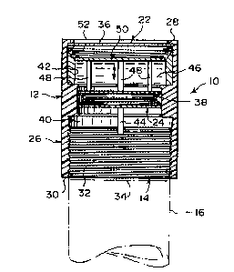
FIGURE 3 is a cross sectional view taken along line 3-3 in Figure 2.
FIGURE 4 is a top view taken in the direction of arrow 4 in Figure 2,
showing visually the tire pressure below a set point.

CA 02269787 1999-04-23
WO 98/18639 PCT/US96/17266
4
FIGURE 5 is a top view similar to Figure 4, showing visually the tire
pressure at the set point or above.
Similar reference characters denote corresponding features consistently
throughout the attached drawings.

CA 02269787 1999-04-23
WO 9S/18639 PCT/ITS96/17266
List of Reference Numbers in the Drawing Figure
visual tire cap pressure gauge
12 cap member of 10
14 securing structure in 12
16 valve stem on 18
18 tire in 20
motor vehicle
22 lens in 12
24 visually indicating assembly

CA 02269787 1999-04-23
WO 98/18639 PCT/US96/17266
6
26 cylindrical hollow housing of 12
28 open top end of 26
30 open bottom end of 26
32 internal threads in 30
34 threaded portion of 16
36 transparent disc-shaped cover for 22
38 diaphragm in 26
40 lower chamber of 26
42 upper chamber of 26

CA 02269787 1999-04-23
WO 98/18639 PCT/US96/17266
7
44 valve depressor rod on 38
46 bright colored fluid in 42
48 rod on 38
50 dark colored plate on 48
52 coil spring in 42

CA 02269787 1999-04-23
WO 98/18639 PCT/US96/17266
8
Detailed Description of the Preferred Embodiment
Turning now descriptively to the drawings, in which similar reference
characters denote similar elements throughout the several views, Figures 1
through 5 illustrate a visual tire cap pressure gauge 10, which comprises a
cap
member 12. A structure 14 within the cap member 12 is for securing the cap
member 12 to a valve stem 16 on a tire 18 in a motor vehicle 20. A lens 22 is
mounted in a top end of the cap member 12. An assembly 24 within the cap
member 12 is for visually indicating when air pressure within the tire 18
drops below a set point, so as to enable a person at a glance to tell if the
tire 18
needs more air.
The cap member 12 is a cylindrical hollow housing 26 ha~~ing an open
top end 28 and an open bottom end 30. The securing structure is internal
threads 32 located within the open bottom end 30 of the cylindrical hollow
housing 26 which can thread onto a threaded portion 34 of the valve stem 16.
The lens 22 is a transparent disc-shaped cover 36 sealed within the open top
end 28 of the cylindrical hollow housing 26, to allow the person to look
through the cover 36 and into the cylindrical hollow housing 26.

CA 02269787 1999-04-23
WO 98/18639 PCT/US96/17266
9
The visual indicating assembly 24 includes a diaphragm 38 mounted
within the cylindrical hollow housing 26, so as to divide the cylindrical
hollow housing 26 into a lower chamber 40 and an upper chamber 42. A
valve depressor rod 44 extends downwardly from a bottom surface of the
diaphragm 38 into the lower chamber 40. The rod 44 will make contact with
the valve stem 16 and release the pressurized air from the tire 18 into the
lower chamber 40, so as to deflect the diaphragm 38 upwardly into the upper
chamber 42 when the air pressure is at the set point.
A bright colored fluid 46 is carried within the upper chamber 42 which
can be readily seen through the lens 22. A plurality of rods 48 extend
upwardly from a top surface of the diaphragm 38 into the upper chamber 42.
A dark colored plate 50 is affixed to top ends of the rods 48, slightly below
the
lens 22 in the upper chamber 42.
A coil spring 52 is between the dark colored plate 50 and the lens 22 in
the upper chamber 42, to normally bias the dark colored plate 50 downwardly
away from the lens 22. In a first instance, as shown in Figure 5, when the air
pressure in the tire 18 is at the set point, the dark colored plate 50 will
move
up towards the lens 22 and be viewed by the person when the diaphragm 38
deflects upwardly.

CA 02269787 1999-04-23
WO 98/18639 PCT/US96/17266
In a second instance, as shown in Figures 3 and 4, when the air
pressure in the tire 1$ is below the set point, the coil spring 52 will push
the
dark colored plate 50 away from the lens 22 allowing the person to view the
bright colored fluid 46 within the upper chamber 42, thereby indicating that
the air pressure in the tire 18 has dropped below the set point.

CA 02269787 1999-04-23
WO 98/18639 PCT/US96/17266
11
Oyeration of the Inventign
To use the visual tire cap pressure gauge 10, the following steps should
be taken:
1. Screw the cap member 12 onto the valve stem 16, so that the
internal threads 32 located within the open bottom end 30 of the cylindrical
hollow housing 2b will thread onto the threaded portion 34 of the valve stem
16.
2. Make sure that the valve depressor rod 44 makes contact with the
valve stem 16, to release the pressurized air from the tire 18.
3. The diaphragm 38 will deflect upwardly into the upper chamber 42
when the air pressure is at the set point, thereby cause the dark colored
plate
50 to move up towards the lens 22 and be viewed by the person.
4. The diaphragm 38 will not deflect upwardly into the upper chamber
42 when the air pressure is below the set point, thereby causing the dark
colored plate 50 to move away from the lens 22 by the help of the coil spring
52.

CA 02269787 1999-04-23
Vu0 98/18639 PCT/U896/17266
12
5. The bright colored fluid can now be seen through the lens 22 by the
person to visually indicate that the tire 18 needs more air.

Dessin représentatif
Une figure unique qui représente un dessin illustrant l'invention.
États administratifs

2024-08-01 : Dans le cadre de la transition vers les Brevets de nouvelle génération (BNG), la base de données sur les brevets canadiens (BDBC) contient désormais un Historique d'événement plus détaillé, qui reproduit le Journal des événements de notre nouvelle solution interne.

Veuillez noter que les événements débutant par « Inactive : » se réfèrent à des événements qui ne sont plus utilisés dans notre nouvelle solution interne.

Pour une meilleure compréhension de l'état de la demande ou brevet qui figure sur cette page, la rubrique Mise en garde , et les descriptions de Brevet , Historique d'événement , Taxes périodiques et Historique des paiements devraient être consultées.

Historique d'événement

Description Date
Inactive : Regroupement d'agents 2013-10-24
Le délai pour l'annulation est expiré 2003-10-28
Lettre envoyée 2002-10-28
Accordé par délivrance 2002-07-16
Inactive : Page couverture publiée 2002-07-15
Inactive : Taxe finale reçue 2002-05-02
Préoctroi 2002-05-02
Un avis d'acceptation est envoyé 2001-11-13
Lettre envoyée 2001-11-13
Inactive : Approuvée aux fins d'acceptation (AFA) 2001-10-30
Inactive : Page couverture publiée 1999-07-22
Inactive : CIB en 1re position 1999-06-10
Inactive : Acc. récept. de l'entrée phase nat. - RE 1999-05-27
Demande reçue - PCT 1999-05-25
Toutes les exigences pour l'examen - jugée conforme 1999-04-23
Exigences pour une requête d'examen - jugée conforme 1999-04-23
Demande publiée (accessible au public) 1998-05-07

Historique d'abandonnement

Il n'y a pas d'historique d'abandonnement

Taxes périodiques

Le dernier paiement a été reçu le 2001-10-22

Avis : Si le paiement en totalité n'a pas été reçu au plus tard à la date indiquée, une taxe supplémentaire peut être imposée, soit une des taxes suivantes :

  • taxe de rétablissement ;
  • taxe pour paiement en souffrance ; ou
  • taxe additionnelle pour le renversement d'une péremption réputée.

Veuillez vous référer à la page web des taxes sur les brevets de l'OPIC pour voir tous les montants actuels des taxes.

Historique des taxes

Type de taxes Anniversaire Échéance Date payée
Taxe nationale de base - petite 1999-04-23
TM (demande, 2e anniv.) - petite 02 1998-10-28 1999-04-23
Requête d'examen - petite 1999-04-23
TM (demande, 3e anniv.) - petite 03 1999-10-28 1999-09-15
TM (demande, 4e anniv.) - petite 04 2000-10-30 2000-10-20
TM (demande, 5e anniv.) - petite 05 2001-10-29 2001-10-22
Taxe finale - petite 2002-05-02
Titulaires au dossier

Les titulaires actuels et antérieures au dossier sont affichés en ordre alphabétique.

Titulaires actuels au dossier
CRAIG CUMMINGS
Titulaires antérieures au dossier
S.O.
Les propriétaires antérieurs qui ne figurent pas dans la liste des « Propriétaires au dossier » apparaîtront dans d'autres documents au dossier.
Documents

Pour visionner les fichiers sélectionnés, entrer le code reCAPTCHA :


Pour visualiser une image, cliquer sur un lien dans la colonne description du document. Pour télécharger l'image (les images), cliquer l'une ou plusieurs cases à cocher dans la première colonne et ensuite cliquer sur le bouton "Télécharger sélection en format PDF (archive Zip)" ou le bouton "Télécharger sélection (en un fichier PDF fusionné)".

Liste des documents de brevet publiés et non publiés sur la BDBC .

Si vous avez des difficultés à accéder au contenu, veuillez communiquer avec le Centre de services à la clientèle au 1-866-997-1936, ou envoyer un courriel au Centre de service à la clientèle de l'OPIC.


Description du
Document 
Date
(aaaa-mm-jj) 
Nombre de pages   Taille de l'image (Ko) 
Page couverture 2002-06-11 1 40
Abrégé 1999-04-23 1 60
Description 1999-04-23 12 198
Dessins 1999-04-23 2 87
Revendications 1999-04-23 2 64
Dessin représentatif 2001-10-31 1 13
Page couverture 1999-07-16 1 50
Dessin représentatif 1999-07-16 1 19
Avis d'entree dans la phase nationale 1999-05-27 1 202
Avis du commissaire - Demande jugée acceptable 2001-11-13 1 166
Avis concernant la taxe de maintien 2002-11-25 1 173
Correspondance 2002-05-02 1 60
Taxes 2001-10-22 2 59
PCT 1999-04-23 7 297
Taxes 1999-09-15 1 59
Taxes 2000-10-20 1 57