Note: Descriptions are shown in the official language in which they were submitted.
CA 02269954 1999-04-26
LOW PRESSURE ACTUATOR
TECHNICAL FIELD OF THE INVENTION
This invention relates to a novel low pressure mechanical
actuator. More particularly, this invention pertains to a novel low
pressure pneumatic or hydraulic device which creates a linear or radial
mechanical force to move components, machinery or control valves.
BACKGROUND OF THE INVENTION
Mechanical actuators with pistons are widely used in industry
for moving parts or components of machinery to carry out various
functions. Actuators are used in assembly lines or industrial processes
to control valves, or to operate equipment. Actuators usually operate
using pneumatic or low pressure hydraulic fluid to create a force, linear
or rotary, to move a component or piece of machinery.
Pneumatic pistons or actuators are of two basic types:
A. Bellows. These typically are hollow and consist of
preformed rubber which extends and contracts in a linear manner by an
"accordion" mechanism extending or collapsing the elastomer. To avoid
radial bulging, the rubber must be very heavy, horizontal movement must
be very short in relation to the radial dimension of the accordion shape,
and pneumatic pressure must be sufficiently low so as not to rupture the
rubber. Bellows type pistons are useful primarily for short thrust, low
pressure movements such as switch or brake activation. Typical
CA 02269954 1999-04-26
-2-
maximum working pressures of bellows type pistons are limited to about
20 psig.
B. Solid tube pistons. These actuators typically comprise
a solid piston sliding within a hollow solid (usually metal) tube. Solid
tube pistons typically operate at working pressures in the range of about
80 psig. To contain the required pneumatic force on the piston, one or
more rubber air seals enclose the circumference of the piston and thereby
contain the air. The air seals are similar to piston rings in an internal
combustion engine. Typically, since the piston moves along the axis of
the interior of the tubular cylinder, a linear force is generated. The term
"actuator" is often applied in situations where a rotary (torque) force is
to be generated. In the case of mechanical actuators, the rotational force
is usually obtained by utilizing a rack and pinion arrangement within the
cylinder. The rack is attached to the piston and the pinion exits the
cylinder radially. This requires a seal (an 0-ring, for example) to
contain the air pressure. Various types of actuators are available, for
example, double action and spring return.
The sliding piston in a fixed cylinder is commonly used for
applications such as valve stem rotation. The inherent problem with this
type is that they are expensive to manufacture and have wear and friction
problems associated with the necessity for sliding seals on the pistons.
Contaminated air can significantly shorten the life of the seals, and the
design of such actuators does not permit economical serviceability. Some
applications therefore require the air to be filtered or otherwise treated to
prolong actuator service life.
CA 02269954 1999-04-26
-3-
Other linear movement mechanisms exist which comprise a
tube that stretches in a linear manner, such as for air ducting used in
ventilation systems. These stretchable tubular mechanisms include plastic
tubing with embedded coiled wire which allows horizontal stretch of the
tubing. The coiled wire provides radial strength. There is an inherent
problem with such tubes. When a high pneumatic pressure is applied to
the tube, it tends to turn and cause localized bulging. Such tubes with
internal or embedded coils are thus suitable only for very low pressure
applications.
Various inventors have attempted to solve the problems
inherent in the designs of these two types of actuators by using a sealed
rubber tube (air bag) and restraining its radial expansion by various
means other than a bellows. These systems generally involve surround-
ing the rubber tube with an outer tube having helical wires. This allows
the outside tube to stretch without bulging. Another method utilizes a
second outside tube with compensating pneumatic pressure. These
systems generally shorten the available stroke of the actuator relative to
its length and also set up counteracting forces which significantly
decrease the mechanical efficiency of the expanding inner tube.
Actuators usually employ one of two methods for activation:
A. The principle of physics that when pressure is applied to
the inside surfaces of an "elastomer bag" of any shape (for example, an
elongated balloon) the pressure will tend to force the bag into a spheroid
CA 02269954 1999-04-26
-4-
shape. Thus the pressure attempts to equalize itself within the confines
of the volume. This is described herein as "equalizing pressure".
B. Restraining radial expansion of an elastomer bag by a
series of two opposed diagonal windings for which the angle of the
crossing points changes to allow some lengthening of the tube until a
maximum angle change occurs. This is described as "radial constraint".
A number of patents have been issued over the years
disclosing various devices that employ one or the other, or both, of
principles A and B above.
Beullens - U.S. Patent No. 4,841,845
Beullens utilizes the equalizing pressure principle. This is
demonstrated by the description of Figures 1 and 2 as being in the
inactive position and Figure 3 as being in the active position. Column 4,
paragraph 40, discloses that "the working points ... are pulled towards
one another". The purpose of the spiral wires in Beullens appears to be
not only to stop the device from "blowing up" but also to redirect the
radial force to a horizontal sucking force when maximum radial size is
reached.
The device comprises on the one hand at least one tightly-
sealable chamber, which is restricted by a wall made from a partially
distortable material, and on the other hand flexible, approximately
unstretchable spiral-wound filaments which extend substantially next to
CA 02269954 1999-04-26
-5-
one another at least about said wall, whereby part of said filaments are
wound rightwards and another part thereof leftwards, and this in such a
way that two arbitrary crossing filaments may undergo some angular
displacement relative to one another, and the one end of each said
filaments on the one side of said chamber is fixed relative to a working
point, and the other end thereof on the opposite side of said chamber is
fixed relative to another working point, and whereby further at least one
feed opening is provided in said chamber, wherethrough a pressurized
gas or liquid may be fed and said wall is distortable at least along one
direction cross-wise to the line joining both said working points, in such
a way that by regulating the gas or liquid pressure inside the chamber,
a relative displacement of said working points occurs.
Negishi - U.S. Patent No. 5.201,262
Negishi utilizes the radial constraint principle. The actuator
of Negishi includes an elastic member extensible in axial directions when
a pressurized fluid is supplied into the elastic member, and a guiding
device arranged inwardly of the elastic member and permitting the elastic
member to move in the axial directions but restraining the elastic member
from moving in directions intersecting the axial directions. The actuator
is of an air-bag type so that energy of the pressurized fluid can be
converted into mechanical movement with high efficiency. The actuator
moves only in axial directions without expanding in radial directions, so
that a space occupied by the actuator in operation is little. Due to the
restrictions of angle change of the "reinforcing braided structure", there
is limited travel of this actuator in relation to its length. This limits its
CA 02269954 1999-04-26
-6-
application. The other "embodiment" (Figure 3a) is the addition of a
return spring outside the actuator.
Negishi - U.S. Patent No. 5.158.005
The device disclosed by Negishi in this patent is very similar
to the device in his U.S. Patent No. 5,201,262, except that the guiding
tube is now outside instead of inside. The actuator of this patent includes
an elastic member extensible in axial directions when a pressurized fluid
is supplied into the elastic member, and a guiding device arranged
outwardly of the elastic member and permitting the elastic member to
move in the axial directions, but restraining the elastic member from
moving in directions intersecting the axial directions. The actuator is of
an air-bag type so that energy of the pressurized fluid can be converted
into mechanical movement with high efficiency. The actuator moves
only in axial directions without expanding in radial directions, so that the
actuator takes up little space in operation. The telescopic tube appears
to be used not to prevent expansion of the elastomer (this is done by the
braided structure) but to keep the piston pointed in the same direction.
If the braided structure were not there, the elastomer would abrade
against and pinch against the telescopic tube. There is limited travel on
this piston.
Negishi - U.S. Patent No. 5.067,390
Negishi, in this case, employs a combination of the
equalizing pressure and radial constraint principles, whereby there are
CA 02269954 1999-04-26
-7-
two concentric pressure tubes. The double-acting actuator of U.S. Patent
No. 5,067,390 includes a tubular body made of an elastic material, with
a first reinforcing braided structure surrounding it. A second tubular
body made of an elastic material surrounds the reinforced braided
structure to form a space outwardly. A second reinforcing braided
structure surrounds the second tubular body. The actuator further
includes closure members for closing and joining ends of the first and
second tubular bodies and reinforcing braided structures, and guiding
device for permitting axial movements of the first and second tubular
bodies but restraining lateral movements thereof. The first and second
reinforcing braided structures are so constructed that initial braided angles
thereof permit of the first braided structure elongating and permit of the
second braided structure contracting when the pressurized fluid is
supplied into the first and second tubular bodies. The fluid pressure is
varied between the tubes so that the outside tube at one point has higher
pressure than the inside tube and thus restrains radial expansion, directing
the force to horizontal thrust. This device also has limited movement.
Sakaguchi - U.S. Patent No. 4,860,639
Sakaguchi discloses a classic example of the equalizing
pressure principle. The actuator of Sakaguchi includes a tubular body
made of a rubber-like elastic material and a braided structure made of
organic or inorganic high-tensile-strength fibers reinforcing an outside of
the tubular body. Closure members sealingly close ends of the tubular
body; at least one of the closure members has a fluid connecting passage.
The tubular body deforms to expand its diameter when pressurized fluid
CA 02269954 1999-04-26
-8-
is introduced through the connecting passage to cause contractive force
in the longitudinal direction. Contraction-detecting strain gauges at one
closure member provide signals corresponding to the contractive force of
the actuator.
Takagi - U.S. Patent No. 4,615,260
This device also operates according to the equalizing pressure
principle with modifications to improve and decrease fatigue. Takagi
discloses a pneumatic actuator including an elastic tubular body, closure
members sealingly closing its ends and a braided structure made of
braided cords reinforcing the tubular body. The braided structure is
expanded in its radial direction and simultaneously contracted in its axial
direction together with the tubular body when pressurized fluid is
supplied into the tubular body. According to the invention the braided
cords of the braided structure comprise monofilaments, each having a
smoothly rounded outer surface of a large radius of curvature. A
protective layer may be provided between the tubular body and the
braided structure or a filler such as an incompressible fluid substance
having no constant shape is provided in the tubular body, or diameters of
both ends of the braided structure and braided angles at both the ends are
made larger than those at a substantially mid-portion of the braided
structure. The actuator according to the invention decreases damage of
the tubular body to elongate its service life and exhibits an improved
contacting performance and high fatigue strength and can greatly save air
consumption to eliminate the disadvantage of much air consumption of
the air-bag type actuator without adversely affecting its advantages.
CA 02269954 1999-04-26
-9-
Wang; - U.S. Patent No. 4.833.973
The fluid pressure actuated assembly disclosed in Wang
includes a casing made of a flexible resilient material, such as rubber or
polyurethane, a coiled tension spring sleeved on the casing for biasing the
casing to move toward a retracted position, and a coiled spacing spring
interposed between the tension spring and the casing for preventing any
wall of the casing from being clamped between any two adjacent turns of
the tension spring. When a compressed fluid is applied to the interior of
the casing, the casing extends. This uses the return spring for radial
restraint, but adds a spacing spring in between to prevent the flexible
material from pinching between the turns of the return spring.
Paynter - U.S. Patent No. 4.108,050
Paynter discloses a method of creating a torque by pressuriz-
ing the inside of a tube having preformed spiral spring wires (helically
shaped) on the outside. The expansion pressure forces the wires to
straighten (ie. lose their spiral) and thus turn one end of the device.
Vergenet - U.S. Patent No. 4,008.008
The invention, among other things, provides a pump adapted
for the intake and delivery of liquid such as water in wells or relatively
deep bodies of water. The pump comprises a rigid-walled chamber,
adapted to be immersed in the liquid to be sucked in. The rigid-walled
chamber has an intake valve and a delivery valve interposed between the
CA 02269954 1999-04-26
-10-
rigid-walled chamber and a delivery tube. The pump is characterized in
that it comprises, accommodated in the rigid-walled chamber, a resiliently
deformable chamber associated with means for controlling, at least in one
direction, alternate deformations of the chamber by expansion and
retraction. This is a device for a submersible pump (well pump, for
example). There is a deformable plunger on the end of the handle at the
top to increase the pressure exerted on the water in the well, forcing the
water up a tube.
Larsson - U.S. Patent No. 4,777,868
Larsson discloses a flexible actuator, comprising at least a
pressure tube, which is axially extendable and/or contractible under
influence of a pressure fluid. The object of the invention is to provide
a flexible actuator, which can perform straight axial movements as well
as curved movements in one or more planes and which can also operate
at very high pressures. These objects have been achieved by the fact that
the tube (12) with the exception of its end, connection or attachment parts
(13) is corrugated and that at least the portions (10) of the corrugated
tube, which are located between its outward projecting folds (9), are
equipped with means (8) of a material which is inextensible as compared
to the material of the tube, and arranged substantially to prevent a radial
expansion and/or contraction of the tube in said portions (10). This is
effectively a very long bellows type with strengthening in the folds of the
bellows to prevent bulging. He has claimed many variations to prevent
the bulging, but all rely basically on the bellows idea and strengthening
with helical wire reinforcing.
CA 02269954 1999-04-26
-11-
Price - U.S. Patent No. 4,006,669
Price discloses a fluid pressure activated piston slidably
carried in a fluid pressure actuated cylinder which, in turn, is slidably
carried in a fixed carrier. Movement of the cylinder is resisted by a
deformable tube frictionally engaged with a fixed circular member. A
predetermined fluid pressure acting across a differential area wall portion
of the cylinder generates a force overcoming the frictional resistance of
the deformable tube engaged with the fixed circular member thereby
advancing the cylinder in the direction of movement of the pressurized
piston. The output force of the piston is substantially unaffected by the
force imposed on the cylinder. This is a very complicated device to be
used for aircraft brake actuation. The only flexible material appears to
be a radially deformable member inside the cylinder to alter the
movements.
SUMMARY OF THE INVENTION
The invention is directed to an actuator comprising: (a) a
flexible hollow fluid impermeable bladder which can be expanded along
an axis when a fluid is introduced into the bladder; and contracted along
the same axis when the fluid is withdrawn from the bladder; (b) a
moveable mechanism associated with the bladder that moves in the same
direction when the bladder expands upon the introduction of fluid into the
bladder.
CA 02269954 1999-04-26
- 12-
The bladder can be expandable in all directions, but is
confined in a restrainer which restricts expansion of the bladder to the
one axis. The fluid can be compressed air or hydraulic oil. A moveable
connector can be associated with a moveable end of the expandable
bladder and can link the bladder to the moveable mechanism. The
moveable mechanism can be a piston. The movable connector can slide
on a restraining rod.
The bladder and moveable mechanism can be housed in a
rigid frame. A fixed connector can be located on an end of the bladder
opposite to the moveable connector and can secure a fixed end of the
bladder to the rigid frame.
The piston can be attached to a yoke which converts axial
motion to rotary motion. The bladder can be attached externally to a
toothed rack acting on a pinion to convert linear motion to rotary motion.
Several rack mechanisms can be fixed radially on a plane, acting on a
common pinion in the centre to create torque and/or return action.
First and second bladders can be placed end to end on
opposite sides of the moveable mechanism and can provide reciprocating
action to the moveable mechanism in either direction along the axis when
fluid is alternatingly introduced into the first and second bladders.
The first and second bladders can have toothed racks which
engage with teeth on the moveable mechanism. First, second, third and
fourth bladders can be arranged in opposing pairs orientation about the
CA 02269954 1999-04-26
- 13 -
moveable mechanism and can actuate the moveable mechanism in unison.
The moveable mechanism can be a gear and the first, second, third and
fourth bladders can have toothed racks which can engage the teeth of the
gear.
The bladder can be made of elastomer. The restrainer can
be made of a collapsible fabric. A spring return can be attached
internally within the bladder, or externally. The bladder can be attached
at each end to the restrainer or attached throughout its length to the
restrainer.
BRIEF DESCRIPTION OF DRAWINGS
In drawings which illustrate specific embodiments of the
invention, but which should not be construed as restricting the spirit or
scope of the invention in any way:
Figure 1 illustrates an elevation of a double-action low
pressure actuator with a yoke attachment according to the invention.
Figure 2 illustrates a plan view of the double-action low
pressure actuator.
Figure 3 illustrates a section view taken along section line A-
A of Figure 1.
CA 02269954 1999-04-26
-14-
Figure 4 illustrates an elevation of a single-action low
pressure actuator, with a yoke attachment.
Figure 5 illustrates a plan view of a single-action low
pressure actuator.
Figure 6 illustrates a detail section of a fabric tube and inner
tube.
Figure 7 illustrates an elevation of four actuators with
toothed racks engaging a common gear.
Figure 8 illustrates a plan view of the four actuator system
illustrated in Figure 7.
DETAILED DESCRIPTION OF SPECIFIC
EMBODIMENTS OF THE INVENTION
The actuator according to the invention works on the
principle of an envelope which is expandable in one direction but not the
other. In the invention, an elastomer tube is affixed at each end to
respective disks of a diameter equal to the diameter of the elastomer tube.
One disk is fixed while the other disk is free to slide axially away from
the fixed disk on guides. Positioned outside the elastomer tube is a
restraining tube which is constructed of a material which has tensile
strength but not compressive strength, such as a woven fabric. The
restraining tube will not stretch at working pressures but will bend or
CA 02269954 1999-04-26
- 15 -
collapse. The restraining tube is of a sufficient length so that when it is
fully extended, the fixed disk and the moveable disk are located at their
maximum distance from each other. As the free sliding disk moves
toward the fixed disk, however, the restraining tube collapses and
crumples. Both the inner elastomer tube and the exterior restraining tube
are fixed at each end to the two end disks in an air tight manner by
known means such as clamps.
The fixed end disk has an orifice through which pneumatic
(or low pressure hydraulic) fluid is applied in a controlled manner by
known means, such as a compressor or pump. The pressure created by
the fluid directed into the elastomer tube causes the elastomer tube to
expand. Since its radial expansion is constrained by the exterior
restraining tube, however, all the generated force is directed axially in
the direction of moving the free sliding disk away from the fixed disk.
Basically, this invention is a fluid pressure actuated cylinder
mechanism which can be used pneumatically (or alternatively, hydrauli-
cally) to create a longitudinal force (such as with pistons) or, when
connected to a yoke, to create a rotary force (torque) (such as with an
actuator). Actuators are commonly used in industrial applications for
mechanically opening and closing valves.
The low pressure actuator according to the invention is
directed to avoiding the problems of the prior art, that is, avoiding the
problem of stretching inherent with bellows type or piston-tube type
actuators by having the restraining tube at rest when fully extended, and
CA 02269954 1999-04-26
- 16-
having the tube crinkle or fold when not extended. In that way, there is
no need to use a material, which is prone to bulging at high pressures
when stretched. A fabric or some other type of flexible outer tube is
suitable for this purpose.
If a woven fabric outer tube is used, the inner elastomer tube
need not be thick as with conventional bellows and can be a very thin
rubber, as it is fully constrained and supported by the fabric. The inner
tube need only be thick enough so as not to bulge between the threads of
the fabric and thus not wear prematurely. Using a thin rubber tube also
has the advantage that it reduces the energy loss that is caused when thick
rubber is stretched. In the invention, the rubber need not have great
strength because the only purpose of the rubber is to contain the
pressurizing fluid.
During the stroke of the actuator piston from the rest
position, where the fabric is deformed, to the extended position where the
tube is fully extended, there is no significant friction wear between the
rubber and the fabric. This is because the rubber initially expands in the
area of least resistance, that is, where the rubber is not in contact with
the fabric. Consequently, there is no significant wear inducing rubbing
between rubber and fabric when fully pressurized.
Existing types of bellows and solid tube piston actuators have
serious shortcomings and limitations. With the bellows actuator, thrust
is limited due to the fluid pressures which can be radially constrained by
this method, and the restricted axial movement.
CA 02269954 1999-04-26
- 17-
Solid tube pistons have the following limitations and
handicaps :
(a) Friction loss;
(b) Seal wear, causing premature failure, and expensive repair
or replacement;
(c) Air contaminants in the air can cause premature wear in
seals, sometimes requiring air filters on the pneumatic
supply to reduce this problem;
(d) Heavy, difficult to handle, thereby causing slower installa-
tion and high maintenance costs in larger sizes;
(e) High manufacturing cost due to close tolerance machining
requirements for movement and air containment; and
(f) Many parts and shapes.
(g) Side thrust when racks attached to opposing pistons act on
a common pinion.
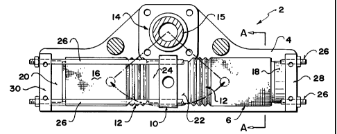
Referring to Figure 1, which illustrates an elevation view of
a low pressure double action actuator 2, and Figure 3, which illustrates
a section view taken along section line A-A of Figure 1, the actuator 2
has a pair of linear rigid frames 4 and 5 on either side (see Figure 3).
In between the two frames 4 and 5 is located an opposing pair of flexible
bellows exterior fabric guide tubes 6 and 16 each of which encloses a
stretchable flexible inner tube 8 (not shown in Figure 1 but see Figure 3)
made of a fluid-proof rubber or elastomer. The exterior fabric guide
tubes 6 and 16 are extendable in a horizontal linear direction but are not
CA 02269954 1999-04-26
- 18 -
extendable in a radial direction. The fabric tubes 6 and 16 have resilient
fluid impermeable inner tubes 8 (see detail in Figure 6).
The opposite exterior ends of the two exterior guide tubes 6
and 16 are respectively connected to fixed end clamps 18 and 20 which
are fixed to the actuator frames 4 and 5 by respective end plates 28 and
30. The interior bellows ends 12 of the two fabric guide tubes 6 and 16
are attached to interior moveable end clamps 22 and 24 on either side of
central piston 10. Piston 10 slides on four tie bars 26 (see Figure 3)
which extend horizontally between the two ends of the longitudinal end
plates 28 and 30 of the actuator 2.
When air is injected through an inlet (not shown) into one of
the inner tubes 8, for example, through end plate 28, on the right in
Figure 1, the pressure of the air causes the inner tube 8 to expand in the
only direction it can, namely towards the piston 10. The radially fixed
bellows portion 12 of the exterior guide tube 6 also expands and moves
the piston 10 to the left. The piston 10 is connected to the rotary yoke
14 and causes shaft 15 to rotate.
The opposite action occurs when the right inner tube 8 and
exterior guide tube 6 are deflated and the left inner tube 8 and exterior
guide tube 16 are inflated. This provides a double-action actuator.
Figure 2 illustrates a plan view of the actuator 2 including
frame plates 4 and 5, exterior fabric guide tubes 6 and 16, reciprocating
CA 02269954 1999-04-26
-19-
piston 10, tie bars 26, first and second fixed end clamps 18 and 20, first
and second free end clamps 22 and 24, and end plates 28 and 30.
The two inner tubes 8 are made of air or oil impermeable
rubber or a similar fluid impermeable flexible elastomeric product. With
the radial constraint created by the two exterior fabric tubes 6 and 16, the
two inner tubes 8 can expand only in an axial direction and cannot
expand radially. The exterior fabric tubes 6 and 16 are attached to the
respective inner tubes 8 only at each end. While an inner tube 8 is in
full tension such as when it is fully inflated (the elastomer is stretched),
the constraining exterior fabric tube 6 or 16, as the case may be, is also
at full length. When the specific inner tube 8 is shortened, such as when
it is deflated, the constraining exterior fabric tube 6 or 16, as the case
may be, folds or buckles in a random manner (see bellows 12 in Figure
1).
Solid metal or plastic disks or clamps 18 and 22 are located
at each end of exterior fabric tube 6, while a second set is located at each
end of exterior fabric tube 16. At one end, the disk 18 is securely fixed
to the end plate 28 and has an entry port to which is attached a fitting for
a pneumatic air supply into the inner tube 8. The disk 22 at the other
interior end of the exterior fabric tube 6 and inner tube 8 is associated
with piston 10 and slides on four guides 26. The disk 22 can be separate
or be part of the piston 10 to which is attached either the fittings for a
yoke 14 for the actuator to impart rotary motion to a shaft 15, or a rod
for transmitting horizontal linear force. The inner tube 8 and the exterior
fabric tube 6 are attached at each end to the disks by removable clamps
CA 02269954 1999-04-26
-20-
18 and 22 (similar to hose clamps). When compressed air is supplied
through the fitting and the fixed disk, the inner tube 8 is inflated and
stretches. At the same time, the exterior fabric tube 6 lengthens and
loses its folds, creases or buckles while at the same time restraining
radial stretching of the inner tube 8. Thus all force due to inflation is
applied axially in the direction of the piston 10.
When the compressed air pressure is released, the exterior
tube 8 returns to its original position, either by means of a spring (not
shown) attached to the piston 10, located either inside or outside the
exterior tube 8 (a single action as illustrated in Figure 4 and 5), or by an
opposed double acting piston (two inner tubes 8 with a common sliding
piston 10 in the middle and a fixed disk at either end), as illustrated in
Figures 1, 2 and 3.
Figure 4 illustrates an elevation of a single-action low
pressure actuator 32. Figure 5 illustrates a plan view of the single-action
low pressure actuator 32. Basically, as seen in Figures 4 and 5, the
single-action actuator 32, comprising a single fabric tube 36, with an
inner elastomer tube 38, is enclosed in a pair of side frames 34 and 35.
In Figures 4 and 5, only an exterior fabric tube 36 is visible. The
interior elastomer inner tube 38 is not visible. One end of the exterior
fabric tube 36 is secured by clamp 42 to end plate 44. The free end of
the exterior tube 36 is secured to a clamp 46 which is connected to piston
40. The movement of the piston 40 by a yoke mechanism 48 imparts a
torque on shaft 50. The longitudinal movement created by inflating or
CA 02269954 1999-04-26
-21-
deflating the resilient inner tube 38 with a pneumatic or hydraulic fluid
is taken up with bellows or wrinkled section 52.
Figure 6 illustrates a cross-section view of a portion of the
fabric guide tube 6 and rubber inner tube 8. The dotted circle is not part
of the invention and is simply a border highlighting the cross-section.
The guide tube 6 and inner tube 8 can be separate from one another or
fused together. In some cases, it may be desirable to form the guide tube
6 and inner tube 6 as one integrated unit.
Figure 7 illustrates an elevation of four actuators with
toothed racks engaging a common gear. As seen in Figure 7, first,
second, third and fourth exterior tubes 54, 56, 58 and 60 are arranged at
90 positions relative to one another. Each of the four tubes 54, 56, 58
and 60 have corresponding racks 62, 64, 66 and 68, protruding from the
interior sides thereof towards and engaging a common central spur gear
70. The four racks 62, 64, 66 and 68 have on one side thereof teeth
which engage the matching teeth of the common spur gear 70. It will be
noted that the tubes function in pairs. In Figure 7, the opposing tubes 54
and 56 are extended while the other opposing pair of tubes 58 and 60 are
compressed. The racks 62, 64, 66 and 68 are restricted from diverging
or jumping off the teeth of the spur gear 70 by respective guide rollers
72, 74, 76 and 78.
Figure 8 illustrates a plan view of the four actuator system
shown in Figure 7. The four tubes 54, 56, 58 and 60, and the racks 62,
CA 02269954 1999-04-26
-22-
64, 66 and 68 are mounted on and held in place by a first frame 80, a
second frame 82 and respective end frames 84 and 86.
The invention is particularly applicable to pneumatic
actuators, which is the most common use, but it should be understood
that the invention has application in other areas as well, including
hydraulics. The figures illustrate preferred embodiments of the inven-
tion. However, it will be understood that a number of variations can be
made which nonetheless represent part of the overall invention. For
example, by using a combination material such as a an elastomer or
rubberized fabric, or other similar material, which is airtight or oil tight,
the outer restraining tube 6 can serve two purposes, thereby eliminating
the need for a separate inner rubber or elastomer tube 8.
Another possible variation is that while the length of the
restraining tube 6, when at rest, is as described above, the length at rest
of the inner rubber or elastomer tube 8 may vary depending on various
factors.
The drawings (particularly Figure 3) illustrate the four
guiding tie bar mechanisms 26 as being exterior to both tubes 6 and 8.
However, for certain applications, the guiding mechanism could be one
or more telescopic tubes affixed to and joining the respective fixed end
clamps 18 and 20 and moveable clamps 22 and 24 inside the inner
elastomer tube 8.
CA 02269954 1999-04-26
- 23 -
Advanta2es. Modifications or Variations of the Invention
(1) Since the radial force is absorbed by the exterior fabric
tube 6, the resilient inner tube 8 can be very thin as it only serves as an
fluid or air seal. The radial force of the air pressure is contained by the
exterior fabric tube 6.
(2) A one-way stretch fabric material of the exterior tube 6
can be embedded, built in or attached to the resilient inner tube 8
throughout the length rather than leaving it attached only at the ends.
(3) The exterior fabric tube 6 can be manufactured either
from a flat fabric with a longitudinal seam to create a tubular shape, or
from fabric woven as a tube.
(4) The exterior fabric tube 6, by shape or content can be
constructed in such a way as to guide the wrinkling effect in a bellows
manner on deflation rather than allowing it to wrinkle in a random
manner.
(5) Depending on the combination of materials used (fabric,
rubber, etc.) there is sometimes a need for a fixed rigid guide tube of
metal or plastic attached to the frame outside the fabric (or flexible tube
if integrated). As seen in Figure 3, the guide tube would be positioned
between the exterior tube 6 and the bars 26. This serves to control
deformation buckling. In the case of actuator use, this guide tube may
CA 02269954 1999-04-26
-24-
have longitudinal slots to allow movement of the force components
attached to the sliding piston.
(6) The piston 10 can be activated by filling the inner tube
8 with a hydraulic fluid rather than pneumatically.
(7) The elastomer inner tube 8, if advantageous, can be
bonded to the exterior fabric tube 6.
(8) The actuator 2 can be single-acting (as seen in Figures
4 and 5) with a spring return (spring attached either inside or outside) or
double-acting as illustrated in Figures 1 and 2. The return force for a
single acting actuator can be provided by a helical spring inside the inner
elastomer tube 8, or an exterior spring return mechanism.
(9) The guide rods 26 which assist axial movement can be
eliminated and replaced by an interior telescoping guide rod internally
attached to a fixed end plate 28 or 30 and corresponding moveable
clamps 22 or 24. Telescoping guides are used in many areas such as
umbrella handles, etc. This modification would not be particularly useful
for a rotational actuator but would be a useful modification for certain
space-limited applications in axial thrust applications.
Methods of Application of the Invention
(1) Figures 1 and 2 of the drawings illustrate a double acting
actuator using a yoke mechanism to convert the axial force to a torque.
CA 02269954 1999-04-26
-25-
Figures 4 and 5 illustrate a single-action actuator which also applies a
torque to a shaft. The yoke and rotary action and shaft can be eliminated
if a linear reciprocating action is required.
(2) "Piston in cylinder" valve actuators commonly use a
rack and pinion assembly for torque creation. In double acting actuators
of this type or dual force actuators (opposing pistons, both giving force
in the same direction) the cylinders are typically manufactured as one in
line tube. When the racks act on opposite sides of the pinions, this
creates a side force due to the offset of each set of teeth from the axial
centre of each cylinder. These handicaps do not exist with the subject
invention because with the subject invention, it is simple to manufacture
an assembly of two opposing cylinders with racks whose teeth are centred
on the axis of their respective cylinders. The two cylinders are mounted
on a plate in such a way as to offset axially from each other sufficient to
direct their resultant force to their respective sides of the common pinion
in the case of a double-acting actuator. In the case of a dual force
actuator, both cylinders are aligned to correctly give the maximum
delivered force to the pinion.
(3) The simple design and the economy of manufacturing
cost, enable a short stroke double-acting dual force rotary actuator to be
constructed using four radially arranged cylinders mounted on a circular
plate and driving a single pinion (see Figures 7 and 8).
CA 02269954 1999-04-26
-26-
Advantages of the Invention
(1) The actuator according to the invention is less expensive
to manufacture than other conventional actuators because there is no
requirement for air seals between moving parts. The actuator is simple
in construction and there is less requirement for machining.
(2) The actuator of the invention is lighter in weight than
current actuators because of fewer parts. Also there is no solid metal
tube.
(3) The only moving parts (excluding the exterior slides and
yoke mechanism) are the elastomer inner tube and exterior fabric tube.
Both these parts are inexpensive to buy and simple and quick for a shop
mechanic to replace with no specialized tools.
(4) There is low wear because apart from the elastomer and
fabric tubes, all other parts are exterior and create almost no environment
for failure or wear.
(5) Contaminated air causes no problems, because there are
no sliding air seals to become clogged or fouled.
(6) When used as a double acting horizontal cylinder, the
travel can be approximately 75 % of total length. This expandability is
very useful in tight confined locations.
CA 02269954 1999-04-26
-27-
As a general rule, typical pneumatic actuators work in the
range roughly of 80 to 100 psig. Normal fabrics such as cotton and the
attendant stitching are not suitable for the exterior tubing because the
cotton will not withstand such pressures without failing. However,
suitable fabrics on the market made from textiles such as NylonTM,
MylarTM, and the like, will withstand such pressures.
Hydraulic actuators can work up to 6000 psig, but typically
for safety reasons work at only 1500 psig. 1500 psig pressure is much
higher than the subject invention will withstand. Generally, there is no
reason to use hydraulics at low pressure because it is uneconomical.
However, an exception is in domestic tap water supply systems. An
actuator according to the invention can operate using domestic water
hookup if there are very few cycles per day. In this application, no air
compressor or hydraulic pump is required and the application is practical
if water consumption is small and only a few cycles a day are required.
As will be apparent to those skilled in the art in the light of
the foregoing disclosure, many alterations and modifications are possible
in the practice of this invention without departing from the spirit or scope
thereof. Accordingly, the scope of the invention is to be construed in
accordance with the substance defined by the following claims.