Note: Descriptions are shown in the official language in which they were submitted.
CA 02270454 1999-04-30
I
INTEGRATED CARD CONSTRUCTION
TECHNICAL FIELD
This invention relates to pressure seal mailers generally, and more
specifically to the incorporation of a clean release card product into a
pressure
seal mailer.
BACKGROUND PRIOR ART
It is known to include ID or other card components within mailer
constructions as disclosed, for example, in commonly owned U.S. Patent No.
~,~34,320. In that case, a discrete card is temporarily adhered to a layer of
stock
material which, in turn, is adhered to the carrier sheet which forms the
mailer. In
another commonly owned U.S. Patent No. 5,650,209, a clean release card is
incorporated in a ''bang tail" type mailer.
Non-mailer printable sheets have also incorporated separable cards, as
disclosed, for example, in U.S. Patent No. x,219,183.
SUMMARY OF THE INVENTION
This invention incorporates a known clean release card construction
within a pressure seal mailer. By integrating the card (or cards) within a
pressure
seal mailer, the latter (including the card) can be printed in a non-impact
printer,
such as a laser printer, without concern for gumming up the printer as often
occurs with heat activated adhesive mailers. In this regard, the card itself
is
CA 02270454 1999-04-30
2
preferably die-cut from the paper stock forming the mailer and does not add
any
appreciable thickness to the mailer. In accordance with the invention, the
paper
carrier stock can be top coated with a laser receptive plastic film, or left
with a
paper face, both of which accept printer toner. In addition, integrating the
card
within the mailer reduces customer labor by eliminating the folding and
stuffing
of cards or forms into an envelope.
In one exemplary embodiment of the invention, a commercially available
laminate assembly is applied to a predetermined area on the underside of a
pressure seal Z-fold (regular or eccentric) mailer in cut or continuous form.
This
laminate assembly is larger on all sides than the one or more cards to be die-
cut
from the opposite side of the form. The laminate assembly includes, from'top
to
bottom, polyester film with an adhesive coating on its top surface and a base
liner
or backing patch top coated with, e.g., a varnish. As purchased, the adhesive
film
is protected by a disposable liner. This assembly is adhesively secured to the
1 ~ underside of the mailer, with the die cuts) for the cards) extending down
through
the paper stock of the mailer and through the polyester film of the laminate
assembly. Even though die cut, however, the varnish provides a temporary and
dry adherence of the card to the base liner or backing patch.
In another embodiment, a form as described above is modified to have an
overlaminate applied over the card (i.e., on the side opposite that which has
the
backing patch. The overlaminate may comprise a laser and signature compatible
polyester or other suitable film adhered to the top surface of the paper card
and
may extend over an area similar to that of the backing patch. It will be
appreciated that neither the card (or cards), backing patch nor the
overlaminate
add any significant thickness to the mailer assembly.
CA 02270454 1999-04-30
3
In still another embodiment, both the upper and lower surfaces of the
paper mailer stock are overlaminated with the same adhesive/polyester material
in
an area larger than the die-cut area.
Variations of the above described embodiments are also described herein,
utilizing different compositions for either the backing or overlaminate
materials
or both.
Accordingly, in its broader aspects, the invention relates to a pressure seal
mailer assembly compatible with non-impact printing techniques, wherein the
mailer assembly includes paper stock with a plurality of interconnected and
foldable panels and pressure activated adhesive along plural edges thereof;
the
improvement comprising at least one opening in one of said panels and a
removable card located and releasably held within the opening; and a laminate
assembly applied to one side of the paper stock covering at least the opening
therein, and wherein part of the laminate assembly remains with the at least
one
I ~ removable card when removed from the paper stock.
In another aspect, the invention relates to a pressure seal mailer
comprising a sheet of paper stock having at least three foldable panels, two
of
which form exterior panels and one of which form an interior panel; the
interior
panel having at least one card incorporated within an opening in the interior
panel
to thereby maintain a substantially uniform thickness across the interior
panel;
and a laminate assembly applied to the underside of the interior panel
overlying
and extending beyond the opening.
Other objects and advantages of the present invention will become
apparent from the detailed description that follows.
CA 02270454 1999-04-30
4
BRIEF DESCRIPTION OF THE DRAWINGS
FIGURE 1 is a partial plan view of a continuous paper stock incorporating
a pressure seal mailer in accordance with an exemplary embodiment of the
invention;
FIGURE 2 is a perspective view of a folded pressure seal mailer in
accordance with the invention;
FIGURE 3A is a partial cross section through a pressure seal mailer as
shown in Figure 1;
FIGURE 3B is a partial section through a pressure seal mailer in
accordance with a second embodiment of the invention;
FIGURE 4 is a partial cross section through a pressure seal mailer in
accordance with another exemplary embodiment of the invention; and
FIGURE ~ is a partial plan view of a panel of a pressure seal mailer in
accordance with the invention, illustrating a particular die-cut arrangement.
DET AILED DESCRIPTION OF THE DRAWINGS
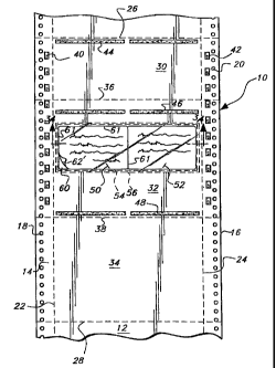
Figure 1 illustrates components of the mailer assembly 10 in a
manufacturing process. Specifically, the form assembly is shown as part of a
continuous paper stock web 12 which includes removable marginal edge strips
14, 16 containing respective tractor feed holes 18, 20, the edge strips
defined by
longitudinally extending perf lines 22, 24. Within the continuous paper stock
web, individual form assemblies are connected by transverse perf lines - for
CA 02270454 1999-04-30
example, the assembly 10 is defined by perf lines 26, 28.. The form assembly
10
includes panels 30, 32 and 34 which are separated by additional longitudinally
spaced, transverse perf lines 36, 38. It will be understood, of course, that
assembly 10 can be produced in a non-continuous manner, i.e., in cut sheet
form,
5 where panels 30, 32 and 34 comprise a single, discreet sheet. The paper
stock is
conventional paper material used in mailer assemblies.
The mailer assembly 10 also includes pressure sensitive adhesive dots and
lines which enable the mailer to be folded and sealed in a conventional manner
after the form has been non-impact printed, as by a laser printer. More
specifically, conventional, permanent pressure sensitive adhesive spots 40, 42
are
located within respective marginal strips 14, 16 while transversely oriented
pairs
of adhesive lines 44, 46, 48 are located along transverse edges of the panels
30
and 32. The adhesive orientation is exemplary only, and many variations are
possible and within the scope of this invention, depending on the exact
1 ~ configuration of the mailer.
In the context of a regular Z-fold mailer, it will be appreciated that panels
30 and 34 sandwich the panel 32 therebetween (see finished assembly 10 in Fig.
2), and therefore it is the "interior" panel 32 which integrates a pair of
cards ~0,
52 in accordance with one example of the invention. In regular Z-fold mailers,
the three panels 30, 32 and 34 are of substantially the same size, while in
eccentric Z-fold mailers, one of the exterior (when folded) panels is smaller
(see
panel 30 in Figure 1 ). The invention here is equally applicable to various
form/fold arrangements.
With reference now to the schematic diagrams of Figures 3A-3B, and
various card integration techniques in accordance with the invention will be
CA 02270454 2006-02-21
6
described. The thicknesses of the various components are not drawn to scale,
and
are enlarged for the sake of clarity. In this regard, one of the features of
the
invention is that the mailer is not appreciably increased in thickness by the
card
construction. The schematic in Figure 3A represents a transverse section
through
the panel 32 of Figure 1. In this embodiment, the underside of the paper stock
web 12 is provided on its underside with a laminate assembly 54 which is
commercially available under the name "Lite-Lift Dry" available from Precision
Coated Products of Batevia, Illinois. Other laminate constructions may be
suitable as well.
I O The assembly ~4 includes a '/ mil to ~ mil polyester film ~6 with a
permanent adhesive ~8 on its top surface (protected during shipping with a
disposable liner, not shown). This film adds a degree of stiffness and
durability
to the cards ~0, ~2. Below the polyester film is a 2~-~0 1b. translucent or
transparent paper base liner or backing patch 60 top coated with a suitable
varnish
1 ~ 62 which "attracts' or temporarily adheres to the polyester film ~6. This
results
in the cards ~0, ~2 remaining temporarily adhered to the mailer even after die
cutting which extends doves through the paper stock 12 and through the
polyester
film ~6.
The laminate assembly extends about '/< inch beyond the area to be die cut
20 on all sides of the card or cards. In the exemplary embodiment, the varnish
top
r
coat 62 may terminate short of the edges of the base liner or backing patch 60
so
that the latter will adhere directly to the polyester film 56 about a
peripheral
border thereof, i.e., outside the card or cards.
The die-cut indicated at 61 and which defines the boundaries of the cards
25 50, 52 can be carried out using a flex plate or roto cylinder.
CA 02270454 2006-02-21
7
If desired, the die-cut can be intermittent, leaving ties
or uncut areas 63 as shown in card 50' in Figure 5. In either
case, the card is easily removed by the addressee by peeling
the card away from the form, leaving the base liner or backing
patch in place.
Turning to Figure 3B, another embodiment is illustrated
where the laminate assembly 54~ (shown only generally instead
of by layer) is as described above, but an overlaminate 64 is
added to the upper surface of the paper stock, over an area
which is approximately the same as the laminate assembly 54'.
The overlaminate 64 is a clear or matte (about 1/2 to 5 mil in
thickness) top coat of laser and signature compatible
polyester or polyvin material, adhesively secured to the paper
stock. The overlaminate 64, like the polyester film 56, adds
rigidity, i.e., stiffness, and durability to the card
construction.
In Figure 4, cards 76, 78 are also formed directly from
the paper stock 80. A polyester or polyvin backing patch 82
is adhesively secured to the underside of the paper stock
including the die-cut cards, while a similar polyester or
polyvin overlaminate 84 is adhesively secured to the upper
surface of the paper stock including the cards. The adhesive
layers are not shown but are similar to layer 58 described
above. The die-cut will extend through the paper stock 80 and
both polyester or polyvin film layers 84, 82. In this
arrangement, it is necessary to use ties or uncut areas such
as those shown at 62 in Figures 5 to hold the cards within the
form.
In all cases, the incorporation of a laminate assembly or
discrete films on upper and lower surface of the paper stock
does not require the mailer to be calendared in order to
pressure seal the edges of the mailer.
CA 02270454 1999-04-30
g
While the invention has been described in connection with what is
presently considered to be the most practical and preferred embodiment, it is
to be
understood that the invention is not to be limited to the disclosed
embodiment,
but on the contrary, is intended to cover various modifications and equivalent
arrangements included within the spirit and scope of the appended claims.