Note: Descriptions are shown in the official language in which they were submitted.
CA 02270496 1999-04-29
Reinforced Hanger Bar
BACKGROUND OF THE INVENTION
1. Field of the Invention
The present invention relates to hanger bars generally. In particular, it
relates to a
reinforced hanger bar construction, and improved hanger bar assembly, and an
improved
hanger bar system.
2. Related Art
A support system is often employed to suspend a member between adjacent
supports. One example of such a support system is found in recessed lighting
assemblies.
It is common to suspend a light fixture between two supports or joists by
attaching the
fixture to a pair of spaced hanger bars. The ends of the hanger bars are then
affixed to the
supports or joists.
Conventional hanger bars can be of a one-piece construction having a fixed
length.
Such a construction can be relatively rigid so as to provide good support for
the suspended
member. However, with this construction the length of the hanger bar cannot be
easily
adjusted thereby limiting its use to supports or joists having a particular
spacing.
Hanger bars of a two-piece construction that have an adjustable length are
known.
While this construction permits installation between supports or joists of
various spacings,
they generally suffer from a lack of stability and fail to provide adequate
support for the
1
CA 02270496 1999-04-29
suspended member. This lack of stability and support is even more pronouced
when the
hanger is installed in its fully extended, or nearly fully extended position.
U.S. Patent Number 5,505,419 to Gabrius discloses a bar hanger for a recessed
lighting system. Each bar hanger is constructed as a one-piece element. The
hanger must
be broken along a score line in order to change its length. The bar hanger has
a stiffening
rib that extends along substantially the entire length of the bar hanger.
U.S. Patent Number 5,029,794 to Wolfe discloses a universal two-piece bar
hanger
construction. Each element of the bar hanger is identical in construction and
has an
elongated slot and two retaining projections. A pair of bar hanger elements
are nested in a
slidable relationship relative to each other.
U.S. Patent Number 4,723,747 to Karp et al. discloses bar hangers for recessed
lighting fixtures. The bar hangers are of a two-piece adjustable construction.
Each bar
hanger has a longitudinally extended "dome'' or projection to facilitate
nesting, as well as
an elongated slot. On hanger bar element has an arrow-shaped retaining
projection while
the other hanger bar element has a foot-like retaining projection. These
retaining
projections are received within elongated slots to couple the hanger bar
elements together in
an adjustable fashion.
CA 02270496 2002-11-06
50078-12
SUMMARY OF THE INVENTION
Accordingly, an object of the present invention is
to provide an adjustable hanger bar assembly that possess
improved strength and stability. A further object is to
facilitate interconnection of the hanger bar elements.
The invention includes an improved hanger bar
member and hanger bar assembly, as well as an improved
hanger bar system including an improved hanger bar member
and assembly.
The invention provides a hanger bar assembly
comprising: a first hanger bar member having a plurality of
slots elongated in a longitudinal direction, and a plurality
of reinforcing formations, said reinforcing formations being
separated from each other in the longitudinal direction by
at least one of said slots, said plurality of slots being
separated from each other in the longitudinal direction by
at least one of said reinforcing formations; a second hanger
bar member interfitted with said first hanger bar member,
said second hanger bar member having a plurality of spaced
retaining projections, at least one of said slots on the
first hanger bar member being engaged by one of said
projections at all times in order to couple said first and
second hanger bar members together in a longitudinally
extensible manner.
3
CA 02270496 2002-11-06
50078-12
An improved hanger bar system consvucted according to the principles of the
present invention may include a plurality of the above-described improved
hanger bar
assemblies spaced from each other, and a suspended member attached to the
improved
hanger bar assemblies.
Figure 1 is a perspective view of a hanger bar system constructed accorain~ to
the
present invention.
Figure ? is an exploded perspec:ive view of a hanger bar assembly includine
first
and second hanger bar elements construc:ed according to the present invention.
Figure 3 is a partial perspective view of a hanger bar assembly according to
the
present invention.
Figure a is a top view of a hanger bar assembly according to the invention in
a fully
extended position.
Figure ~ is a side view of the hanger bar assembly of Figure ~.
Figure 6A is a top view of a hanger bar assembly according t~o the invention
in a
partially extended position.
Figure 6B is a top view of a hanger bar assembly according to the invention in
a
?0 fully retracted position.
Figure 7 is a cross-sectional view taken along line 7-7 of Figure 4.
CA 02270496 1999-04-29
Figure 8 is a cross-sectional view taken along line 8-8 of Figure 4. .
Figure 9 is a cross-sectional view taken along line 9-9 of Figure 4.
Figure 10 is a cross-sectional view taken along line 10-10 of Figure 4.
Figure 11 is a partial sectional view of a securing arrangement for a hanger
bar
system constructed according to the invention.
DETAILED DESCRIPTION OF THE PREFERRED EMBODIMENTS
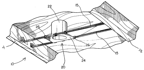
An improved hanger bar system constructed in accordance with the principles of
the
present invention is illustrated in Figure 1. The improved hanger bar system
includes a
pair of spaced hanger bar assemblies 15 that are attached to parallel support
members or
joists J1 and J2. A suspended member 20 is mounted between the hanger bar
assemblies
15.
By way of example, the suspended member 20 can comprise a light fixture
assembly
22. The light fixture assembly 22 is mounted to the hanger bar assemblies 15
by a plaster
plate 24. The plaster plate 24 includes attachments tabs 26 that attach the
plaster plate 24 to
the hanger bar assemblies 15. The attachment tabs 26 further act to secure
each individual
hanger bar element of the hanger bar assembly 15 together.
Each hanger bar assembly 15 is of a two-piece construction that is adjustable
in a
length-wise or longitudinal direction. Each hanger bar assembly 15 comprises
two separate
hanger bar members 30 and 60, as illustrated in Figure 2.
CA 02270496 1999-04-29
The first hanger bar member 30 includes a first end 32 that has chamfered
corners
34. The corners 34 can be chamfered at any desired angle. By way of example,
the
corners can be chamfered at a 45 degree angle relative to the longitudinal
direction.
First hanger bar member 30 further includes a first elongated slot 36. In its
preferred form, first elongated slot 36 has a first width 40 proximate the
first end 32 and
extending along a substantial portion of its longitudinal dimension. The slot
36 may further
comprise a second width 42 which is greater than the first width 40. An angled
transitional
surface 41 (as illustrated best in Figure 4) connects the first width 40 with
the second width
42. By way of example, the angled surface 41 can be disposed at a 45 degree
angle relative
to the longitudinal direction as indicated by the angle ''x" in Figure 4.
A first score line 49 may be formed across the width of the first hanger bar
member
30. The precise form and dimensions of the score line 49 can vary. widely. In
the example
illustrated, the score line is a straight line and is approximately .02 inches
deep. In the
event that it becomes necessary to fit between relatively narrowly spaced
support members,
the first hanger bar member 30 can be broken along first score line 49 to
shoiten its length.
A first reinforcing formation 44 is provided between the first elongated slot
36 and a
second elongated slot 38. As shown, for example, in Figure 2, the second width
42 of the
first slot 36 is preferably provided in the area of the first reinforcing
formation 44.
6
CA 02270496 1999-04-29
The second elongated slot 38 also includes first width 40, which extends along
a
substantial portion of the longitudinal dimension of the slot 38, and a second
width 42. The
second width 42 is provided at both ends of the longitudinal slot 38. A second
reinforcing
formation 46 is provided that extends from one end of elongated slot member 38
to a
second end 48 of the first hanger bar member 30.
An attachment structure 50 is provided at the second end 48. The attachment
structure 50 may be integrally formed with the first hanger bar member 30 or
may be
separately formed and subsequently attached to the second end 48.
One example of an attachment structure ~0 is illustrated in Figure 2. The
illustrated
example includes an end mounting plate ~2 having an aperture 54 disposed
therein and an
integral tab 56. The free end of the tab 56 includes wedge-shaped serrations
~8. The end
mounting plate 52 may be cut and folded to form the aperture 54 and tab 56.
The
attachment structure can be secured to a support member of joist by striking
the tab member
56 with a hammer thereby driving the free end into the support member or
joist. The
wedge shaped serrations facilitate entry of the tab into the support member
and also further
act to retain the tab within the support member.
A second hanger bar member 60 is provided that nests with the first hanger bar
member 30. A second hanger bar member 60 includes a first end 62 which
includes
chamfered comers 64 similar to the chamfered corners 34 of the first hanger
bar member.
7
CA 02270496 1999-04-29
First and second retaining projections 66 and 68 are provided proximate the
first end
62. The first and second retaining projections 66 and 68 may be any suitable
shape or
form. One preferred example is an arrow shape, as illustrated in Figure 2. The
retaining
projection 66 and 68 are received within the first and/or second elongated
slots 36 and 38
of the first hanger bar member in order to couple the hanger members together
in a
longitudinal adjustable manner. The head of the retaining projection is
greater in width
than the first width 40 of slots 36 and 38, but is smaller than the second
width 42.
Therefore the retaining projections 66 and 68 may be freely inserted through
the slots 36
and 38 at the second width 42, but not at the first width 40. As illustrated
in Figure 3, the
retaining projections 66 and 68 are dimensioned so as to pass freely through
the first and
second reinforcing formations 44 and 46 as the first and second hanger bar
members 30 and
60 are longitudinally moved relative to each other. The first and second
retaining
projections 66 and 68 may be cut from the surface of the second hanger bar
member 60 and
unfolded to provide the form illustrated in Figure 2. Alternativelx, the first
and second
retaining projections 66 and 68 may be separately formed then attached to the
surface of the
second hanger bar member 60.
A second score line 67 may be provided across the width of the second hanger
bar
member 60. As with the first score line 49, the precise form and depth may
vary widely
according to the material strength and thickness of the hanger bar members. By
way of
example only, the score line may be a straight line formed to a depth of
approximately .02
inches. Since second hanger bar member 60 is of a solid cross-section, unlike
slotted
hanger bar member 30, it is more difficult to break along the score line.
Therefore, a
8
CA 02270496 1999-04-29
scoring window or aperture 69 may optionally be provided in the area of the
score line 67
in order to facilitate breakage of the hanger bar member.
In the event that it becomes necessary to fit the hanger bar assembly into a
relatively
narrow space, the second hanger bar 60 may be broken along score line 67. As
shown in
Figure 2, breaking the hanger bar along score line 67 removes the end of the
hanger bar 60
having retaining projections 66 and 68. However, the first and second hanger
bar members
are still adequately retained by the attachment tabs 26 formed on the plaster
plate 24.
The second hanger bar member 60 may extend with a uniform cross-section to a
second end 70. An attachment structure ~0 is provided at the second end 70. As
with the
first hanger bar member the attachment structure 50 can be of any suitable
form. In one
preferred form, the attachment structure 50 disposed at the second end 70 has
the same
construction as the first attachment structure located at second end.48 of the
first hanger bar
member 30. The elements of the attachment structure ~0 have been previously
described in
connection with the description of first hanger bar member 30.
As mentioned above, the first and second hanger bar members are secured
together
in a nested manner. In particular, the first hanger bar member 30 has a first
surface 72
which faces the second hanger bar 60 when assembled, and a second opposing
surface 74.
The second hanger bar member 60 includes a third surface 76 which faces away
from the
first hanger bar 30 when assembled, and a fourth surface 78 which faces the
first hanger
bar 30. When the first and second hanger bar members are connected, the first
and fourth
9
CA 02270496 1999-04-29
surfaces 72 and 78 are received within each other in a nesting relationship.
.The second
surface 74 faces outwardly (e. g. - away from the suspended member 20) and the
third
surface 76 faces inwardly (e.g. - toward the suspended member 20).
One advantage of the relatively large width areas 42 is that assembly of the
first and
second hanger bar members 30 and 60 to each other is facilitated. As
previously noted, the
retaining projections 66 and 68 may pass freely through the second width 42
without
interference.
One possible method of assembly is described as follows. The second retaining
projection 68 is first passed through the second width 42 proximate the second
reinforcing
formation 46. The second hanger bar 60 is then moved back relative to the
first hanger bar
member 30 in the direction of the first end 32. The second retaining
projection 68 then
travels and is engaged in the first width 40 of the second slot 38. The first
retaining
projection 66 is subsequently inserted through the second width 42 proximate
the second
reinforcing formation 46. As the second hanger bar member 60 is moved
continually
toward the first end 32, the first retaining projection 66 will then engage
second elongated
slot 38 in a similar fashion thereby securing the first and second hanger bar
members 30
and 60.
Once the first and second hanger bar members 30 and 60 are connected, the
resulting hanger bar assembly 15 is freely adjustable in a length-wise or
longitudinal
?0 direction. The hanger bar assembly 15 is shown in its fully extended
position in Figures 4
CA 02270496 1999-04-29
and 5. Figure 6A shows the hanger bar assembly 15 in a partially extended
position.
Figure 6B shows the hanger bar assembly 15 in its fully retracted position.
One
particularly advantageous aspect of the present invention is that as the first
and second
hanger bar members 30 and 60 are moved relative to each other at least one
retaining
projection is engaged within one of the elongated slots 36 and 38 at all
times. This
construction is made possible by providing the first and second retaining
projections 66 and
68 with a predetermined spacing S1 (as shown, for example, in Figure 3).
Preferably, the
predetermined spacing S1 is made at least slightly larger than the distance
between the first
width regions 40 of the first and second elongated slots 36 and 38 which are
separated by
the first reinforcing formation 44. This dimension is illustrated as reference
element 205 in
Figure 6A.
As illustrated in Figure 6B, when the hanger bar assembly 15 is in its fully
retracted
or collapsed condition, the second retaining projection 68 is maintained in
engagement with
the first width 40 of slot 38 by providing a predetermined spacing SZ which
extends from
the second retaining projection 68 to the first end 62 of the second hanger
bar member 60.
This predetermined spacing Sz is greater than the distance between the first
width 40 of the
second elongated slot 38 and the end mounting plate surface 52 of the first
hanger bar
member. This dimension is indicated by element 193 in Figures 6A and 6B.
The cross-sectional details of the hanger bar assembly according to the
present
invention are best illustrated in Figures 7-10. Figure 7 shows the first and
second hanger
bar members 30 and 60 in a nested relationship. As previously described and
illustrated in
11
CA 02270496 1999-04-29
Figure 2, the first hanger bar member 30 has a first surface 72 and a second
surface 74.
The first surface 72 has a generally concave groove 82 disposed along ~
substantial portion
of the longitudinal length of the first hanger bar member 30. The second
surface 74 has a
generally convex ridge 84 corresponding to the concave groove 82 formed on
said first
surface. The third surface 76 of second hanger bar member 60 has a generally
concave
groove 86 extending along a substantial portion of longitudinal length of the
second hanger
bar member 60. The second hanger bar member 60 further has a generally convex
ridge 88
disposed on the fourth surface 78 corresponding to the concave groove 86. As
illustrated in
Figure 7, the generally convex ridge 88 is received in the generally concave
groove 82 in a
nested manner.
Figure 8 is a cross-sectional view of the first hanger bar member 30 showing
the
first width 40 of the elongated slot. Figure 9 is a cross-sectional view of
the first hanger
bar member 30 showing the second width 42 of the elongated slot and just prior
to a
reinforcing formation. Figure 10 is cross-sectional view of the first hanger
bar member 30
showing a reinforcing formation in an area which does not include any
elongated slot.
The first and second reinforcing formations 44 and 46 each have a generally
concave reinforcing depression 92 disposed along first surface 72 and a
generally convex
reinforcing protrusion or ridge formed along the second surface 74. As
illustrated for
example in Figure 9, the generally concave groove 82 which extends along a
substantial
portion of the first hanger bar member 30 defines a first plane P1. By
comparison, the
generally concave reinforcing depressions 92 extend beyond the plane P1 and
are therefore
12
CA 02270496 1999-04-29
formed deeper into the first hanger bar member 30. Similarly, the generally
convex ridge
84 which extends along a substantial portion of the longitudinal length of the
first hanger
bar member 30 defines a second plane P2. The reinforcing protrusion 94 extends
beyond
plane P2 so as to project further from the surface of the first hanger bar
member 30.
Another aspect of the present invention is illustrated in Figure 11. A
securing
arrangement may be provided for the hanger bar system that fixes the position
of the first
and second hanger bar members 30 and 60 to each other, as well as fixes the
position of the
hanger bar assemblies 15 relative to the suspended member. One example of such
an
arrangement is shown in Figure 11. The plaster plate 24 has attachment tabs 26
that retain
the first and second hanger bars 30 and 60. A securing fastener 25, such as a
threaded
screw, is received in an aperture of a guide flange member 27. An aperture 29
is provided
in the plaster plate to provide access to the securing fastener 25. As the
securing faster is
tightened, it comes into contact with a surface of the second hanger bar
member 60. As a
result of this contact, the first and second hanger bars 30, 60 come into
firmer engagement
with each other as well as with the attachment tabs 26. Therefore this
increased contact
pressure prevent the first and second hanger bar members from moving relative
to each
other, as well as preventing the hanger bar members 30, 60 from moving
relative to the
attachment tabs 26 and the plaster plate 24.
Only preferred embodiments of the invention are specifically illustrated and
described herein. It should be appreciated that numerous modifications and
variations of
the present invention are possible in light of the present disclosure, such
modifications and
13
CA 02270496 1999-04-29
variations being encompassed within the scope of the appended claims without
departing
from the spirit an scope of the present invention.
14