Language selection

Search

Patent 2270570 Summary

Third-party information liability

Some of the information on this Web page has been provided by external sources. The Government of Canada is not responsible for the accuracy, reliability or currency of the information supplied by external sources. Users wishing to rely upon this information should consult directly with the source of the information. Content provided by external sources is not subject to official languages, privacy and accessibility requirements.

Claims and Abstract availability

Any discrepancies in the text and image of the Claims and Abstract are due to differing posting times. Text of the Claims and Abstract are posted:

  • At the time the application is open to public inspection;
  • At the time of issue of the patent (grant).
(12) Patent Application: (11) CA 2270570
(54) English Title: SLEEVE ANCHOR
(54) French Title: DISPOSITIF D'ANCRAGE A RETENUE
Status: Deemed Abandoned and Beyond the Period of Reinstatement - Pending Response to Notice of Disregarded Communication
Bibliographic Data
(51) International Patent Classification (IPC):
  • F16B 13/06 (2006.01)
(72) Inventors :
  • MCDUFF, PIERRE R. (Canada)
  • NGUYEN, LANG (Canada)
(73) Owners :
  • COBRA FIXATIONS CIE LTEE - COBRA ANCHORS CO. LTD.
(71) Applicants :
  • COBRA FIXATIONS CIE LTEE - COBRA ANCHORS CO. LTD. (Canada)
(74) Agent: NORTON ROSE FULBRIGHT CANADA LLP/S.E.N.C.R.L., S.R.L.
(74) Associate agent:
(45) Issued:
(22) Filed Date: 1999-04-30
(41) Open to Public Inspection: 2000-10-30
Availability of licence: N/A
Dedicated to the Public: N/A
(25) Language of filing: English

Patent Cooperation Treaty (PCT): No

(30) Application Priority Data: None

Abstracts

English Abstract


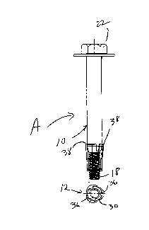
A sleeve bolt (A) for insertion in a hole
delimited by a wall comprises a threaded fastener
(10) and an expansion sleeve (12). The threaded
fastener (10) has a stem (14) that includes a
proximal cylindrical shank (16) and a distal threaded
section (18). The shank (16) has substantially the
diameter of the hole and defines at a distal end
thereof a conical expander portion (20). The
expansion sleeve (12) comprises a distal threaded
member (26) and a proximal expansion member (28), the
threaded member (26) being threadably engaged to the
threaded section (18) of the stem (14). The expansion
member (28) includes anchor legs (32) each having a
proximal end (38) adapted, upon axial displacement of
the expansion sleeve (12) towards the shank (16)
resulting from a rotation of the stem (14), to engage
the conical expander portion (20) such as to expand
the proximal ends (38) of the anchor legs (32) of the
expansion member (28) outwardly into engagement with
the wall. The expansion member (28) fractionally
engages the wall upon introduction of the stem (14)
in the hole.


Claims

Note: Claims are shown in the official language in which they were submitted.

CLAIMS:
1. A sleeve bolt for insertion in a hole delimited
by a wall, comprising a threaded fastener and an
expansion means, said threaded fastener having a
stem, said stem including a proximal stem section and
a distal threaded section, said proximal stem section
having substantially a diameter of the hole and being
provided at a distal end thereof with an expander
means, said expansion means being adapted to be
threadably engaged onto said distal threaded section
and having a proximal end adapted, upon axial
displacement of said expansion means towards said
proximal stem section resulting from a rotation of
said stem, to engage said expander means such to
expand outwardly into engagement with the wall.
2. A sleeve bolt as defined in claim 1, wherein
said expansion means comprise a distal threaded
member and a proximal expansion wedge, said threaded
member being adapted to be threadably engaged to said
threaded section of said stem, said expansion wedge
being adapted to frictionally engage the wall upon
introduction of said stem in the hole while said
threaded member is spaced from the wall such that,
upon sufficient subsequent rotation of said stem,
said expansion means displace towards said expander
means.
3. A sleeve bolt as defined in claim 2, wherein a
transversal size of said expander means reduces in
direction of said distal threaded section of said
stem such that, upon displacement of said expansion
wedge along said distal threaded section and towards
said expander means, a proximal end of said expansion
wedge engages said expandex means and gradually
expands outwardly.
7

4, A sleeve bolt as defined in claim 3, wherein
said expander means defines a taper.
5. A sleeve bolt as defined in claim 4, wherein
said expander means comprises a frusto-conical
portion.
6. A sleeve bolt for insertion in a hole
delimited by a wall, comprising a threaded fastener
and an expansion means, said threaded fastener having
a stem, said stem including a proximal stem section
and a distal threaded section, said proximal stem
section being provided at a distal end thereof with
an expander means, said expansion means being adapted
to be threadably engaged onto said distal threaded
section and having a proximal end adapted, upon axial
displacement of said expansion means towards said
proximal stem section resulting from a rotation of
said stem, to engage said expander means such to
expand outwardly into engagement with the wall.
7. A sleeve bolt as defined in claim 6, wherein
said expansion means comprise a distal threaded
member and a proximal expansion wedge, said threaded
member being adapted to be threadably engaged to said
threaded section of said stem, said expansion wedge
being adapted to frictionally engage the wall upon
introduction of said stem in the hole while said
threaded member is spaced from the wall such that,
upon sufficient subsequent rotation of said stem,
said expansion means displace towards said expander
means.
8. A sleeve bolt as defined in claim 7, wherein a
transversal size of said expander means reduces in
direction of said distal threaded section of said
stem such that, upon displacement of said expansion
wedge along said distal threaded section and towards
8

said expander means, a proximal end of said expansion
wedge engages said expander means and gradually
expands outwardly.
9. A sleeve bolt as defined in claims 7 and 8,
wherein said threaded member of said expansion means
comprises a conical section which tapers towards said
expansion wedge, said conical section being adapted,
upon sufficient rotation of said stem and once said
expansion wedge is substantially stationary onto said
expander means, to displace towards and relative to
both said expander means and said expansion wedge
such that said conical section causes a distal end of
said expansion wedge to expand outwardly into
engagement with the wall.
10. A method of setting a sleeve bolt in a hole
delimited by a wall, comprising the steps of: (a)
providing a threaded fastener and an expansion means
threadably engaged to a distal end of said fastener;
(b) inserting said expansion means and part of said
threaded fastener in the hole; (c) rotating
sufficiently said fastener with said expansion means
being fractionally engaged to the wall for causing
said expansion means to displace towards a proximal
end of said fastener and for causing a proximal end
of said expansion means to be expanded by said
fastener into engagement with the wall.
11. A method as defined in claim 10, wherein said
fastener has a stem, said stem including a proximal
stem section and a distal threaded section, said
proximal stem section having substantially a diameter
of the hole and being provided at a distal end
thereof with an expander means for expanding said
expansion means in step c), said expansion means
being adapted to be threadably engaged onto said
distal threaded section and having a proximal end
9

adapted, upon axial displacement of said expansion
means towards said proximal stem section resulting
from a rotation of said stem, to engage said expander
means such to expand outwardly into engagement with
the wall.
12. A method as defined in claim 11, wherein said
expansion means comprise a distal threaded member and
a proximal expansion wedge, said threaded member
being adapted to be threadably engaged to said
threaded section of said stem, said expansion wedge
being adapted to fractionally engage the wall upon
introduction of said stem in the hole while said
threaded member is spaced from the wall such that,
upon sufficient subsequent rotation of said stem,
said expansion means displace towards said expander
means.
13. A method as defined in claim 12, wherein a
transversal size of said expander means reduces in
direction of said distal threaded section of said
stem such that, upon displacement of said expansion
wedge along said distal threaded section and towards
said expander means, a proximal end of said expansion
wedge engages said expander means and gradually
expands outwardly.
14. A method as defined in claim 13, wherein said
expander means defines a taper.
15. A method as defined in claim 14, wherein said
expander means comprises a frusto-conical portion.
10

Description

Note: Descriptions are shown in the official language in which they were submitted.


CA 02270570 1999-04-30
SLEEVE ANCHOR
BACKGROUND OF THE INVENTION
1. Field of the Invention
The present invention relates to fasteners
and, more particularly, to expandable fasteners for
mounting to concrete structures, and the like.
2. Description of the Prior Art
Expandable anchors of many different types
are already known. More particularly, expandable
anchors have been developed for insertion into a hole
formed in a support structure such that an expansion
sleeve of the anchor may be selectively expanded into
frictional contact with the inside peripheral surface
of the hole such that the anchor becomes fractionally
anchored in the support structure. Typically, the
expandable anchor includes an elongated expander
member having a threaded first end and a flared
second end opposite the first end with a cylindrical
surface extending between the first and second ends
around which there is provided the aforementioned
expansion sleeve which generally has the shape of a
cylinder. The threaded first end is like a headless
screw and extends outwardly of the support structure
once the expandable anchor is positioned in the hole
thereof. A nut threaded on the visible part of the
threaded first end may be used as an actuating
mechanism with an object to be secured to the support
structure being typically located between the nut and
the support structure as the threaded first end of
the expandable anchor extends through this object.
By rotating the nut, it engages the outer surface of
the object and thus bears upon it such as to pull the
expander member in an outward direction. As the
expansion sleeve is already sufficiently fractionally
engaged with the inside surface of the hole, when the
expandable anchor is pulled by the rotation of the
1

CA 02270570 1999-04-30
nut, the expansion sleeve stays substantially
stationary in the hole and thus, as the expander
member is pulled out of the hole, the flared second
end of the expander member causes the radial
expansion sleeve to expand outwardly thereby
increasing a friction between the expansion sleeve
and the hole and thus securing the expandable anchor
therein.
Since the expansion sleeve must already be
fractionally engaged with the hole before the
expandable anchor is pulled, the outside diameter of
the expansion sleeve must be similar to the inside
diameter of the hole and even slightly greater
therefrom in order to ensure an initial frictional
contact therebetween which will then allow the
expansion sleeve to remain still in the hole while
the expander member is pulled outwardly thereof and
thus allow the expansion sleeve to be expanded by the
flared end of the expander member. This diameter of
the expander member, at rest, results in that the
expandable anchor when initially inserted in the hole
must be inconveniently driven with significant force
therein as the expansion sleeve is already
fractionally engaged with the inside wall of the
hole. The flared end acts as a wedge to expand the
expansion sleeve into greater frictional contact with
the inside of the hole.
Also known are undercut wedge anchors,
wherein the hole formed in the support structure is
enlarged at a distance from the visible opening of
the hole such that the expansion sleeve may be
inserted behind a shoulder defined at the junction of
the enlarged area and the remainder of the hole.
Once expanded, the expansion sleeve may abut this
shoulder and thus retain the anchor in position in
the support structure.
2

CA 02270570 1999-04-30
SUN~iARY OF THE INVENTION
It is therefore an aim of the present
invention to provide an improved expandable anchor
for use in holes in various materials, e.g. concrete.
It is also an aim of the present invention
to provide an expandable anchor, such as a sleeve
anchor, having an expander member and an expansion
member capable of spring-like deformation.
BRIEF DESCRIPTION OF THE DRAWINGS
Having thus generally described the nature
of the invention, reference will now be made to the
accompanying drawings, showing by way of illustration
a preferred embodiment thereof, and in which:
Figs. 1 to 3 are front elevational views of
a sleeve anchor in accordance with the present
invention shown respectively in first, second and
third positions thereof;
Figs. 4 to 6 are bottom plan views of the
expansion sleeve of the sleeve anchor of Figs. 1 to
3;
Fig. 7 is a top plan view of the sleeve
anchor of Figs. 1 to 3;
Figs. 8 and 9 are respectively front
elevational and top plan views of the fastener of the
sleeve anchor of Figs. 1 to 3;
Figs. 10 and 11 are respectively front
elevational and bottom plan views of the threaded
member of the expansion sleeve of the sleeve anchor
of Figs. 1 to 3;
Fig. 12 is a plan view of the expansion
member of the expansion sleeve of the sleeve anchor
of Figs. 1 to 3, this expansion member being shown in
its initial manufactured state, i.e. before being
shaped for use in the sleeve anchor;
Figs. 13 to 15 are respectively front
elevational and top and bottom plan views of the
3

CA 02270570 1999-04-30
expansion member of Fig. 12, but shown in its
position for mounting to the threaded member of Figs.
10 and 11;
Figs. 16 to 18 are respectively front
elevational, vertical cross-sectional and top plan
views of a second embodiment of the sleeve anchor of
Figs. 1 to 3, also in accordance with the present
invention; and
Figs. 19 to 21 are front elevational,
vertical cross-sectional and top plan views of the
home expansion sleeve of the sleeve anchor of Figs.
16 to 18.
DESCRIPTION OF THE PREFERRED EMBODIMENTS
In accordance with the present invention,
Figs . 1 to 3 illustrate a sleeve anchor A comprising
a threaded fastener 10 and an expansion sleeve 12.
The fastener 10 includes a stem 14 having a proximal
smooth cylindrical section 16, a reduced diameter
threaded distal section 18 and an intermediate
frusto-conical section 20. The fastener 10 also
includes a bolt head 22 and a washer 24 , both to be
located outside of the hole defined in a structure,
in which hole the stem 14 is to be inserted such that
an object may be held secure by the bolt head 22
against the structure.
The expansion sleeve 12 includes a
cylindrical internally threaded member 26 (Figs. 10
and 11 ) and an expansion member 3 0 (Figs . 12 to 15 ) .
The expansion member includes a central ring 30 and,
for instance, three anchor legs 32 extending
therefrom. When the threaded member 26 and the
expansion member 28 are assembled together as in
Figs. 1 to 6, narrow sections 34 of the legs 32 are
lodged in notches 36 defined on the periphery of the
threaded member 26.
4

CA 02270570 1999-04-30
The threaded section 18 of the fastener 10
is adapted to threadably mated with the threaded
member 26 of the expansion sleeve 12 with the
threaded section 18 extending through the central
ring 30 and with the legs 32 extending exteriorly
along the threaded section 18, as seen in a first or
inoperative position of the sleeve anchor A shown in
Fig. 1.
When the sleeve anchor A of Fig. 1 is
positioned in the aforementioned hole defined in the
support structure, the expansion sleeve 12
fractionally contacts the walls of the hole in a
sufficient manner such that the subsequent rotation
of the fastener 10 by way of its bolt head 22 will
cause the fastener 10 to move further into the hole
of the structure, as the expansion sleeve 12 remains
stationary in the hole (in view of its frictional
contact with the walls thereof) and in view of the
threaded engagement of the distal section 18 of the
fastener 10 with the threaded member 26 of the
expansion sleeve 12. Indeed, the rotation of the
fastener causes the same to displace through the
expansion sleeve 12 , whereby, as seen in Figs . 2 and
3, the expansion sleeve 12 is displaced relative to
the fastener 10 such that the legs 32 thereof climb
along the frusto-conical section 20 of the stem 14 of
the fastener 10 and are forced outwardly by the
frusto-conical section 20 until the proximal edges 38
of the legs 32 come into strong angled engagement
with the walls of the hole. The angle of the legs 32
in Fig. 3 and their engagement with the walls of the
hole prevent the anchor sleeve A from being forcibly
removed form the hole.
In Figs . 16 to 21 , a variant sleeve anchor
A' includes the same fastener 10 which is now used
with an expansion sleeve 12' having four legs 32'.
The expansion sleeve 12' is also of unitary
5

CA 02270570 1999-04-30
construction in that the threaded member and
expansion members 26 and 28 of the sleeve anchor A of
Figs. 1 to 15 are manufactured integrally with each
other.
6

Representative Drawing
A single figure which represents the drawing illustrating the invention.
Administrative Status

2024-08-01:As part of the Next Generation Patents (NGP) transition, the Canadian Patents Database (CPD) now contains a more detailed Event History, which replicates the Event Log of our new back-office solution.

Please note that "Inactive:" events refers to events no longer in use in our new back-office solution.

For a clearer understanding of the status of the application/patent presented on this page, the site Disclaimer , as well as the definitions for Patent , Event History , Maintenance Fee  and Payment History  should be consulted.

Event History

Description Date
Time Limit for Reversal Expired 2004-04-30
Application Not Reinstated by Deadline 2004-04-30
Deemed Abandoned - Failure to Respond to Maintenance Fee Notice 2003-04-30
Application Published (Open to Public Inspection) 2000-10-30
Inactive: Cover page published 2000-10-29
Letter Sent 2000-09-14
Inactive: Transfer information requested 2000-09-13
Inactive: Inventor deleted 2000-09-12
Inactive: Delete abandonment 2000-09-08
Inactive: Abandoned - No reply to Office letter 2000-08-02
Inactive: Single transfer 2000-08-02
Inactive: Correspondence - Formalities 2000-07-31
Inactive: First IPC assigned 1999-06-17
Inactive: Filing certificate - No RFE (English) 1999-06-03
Filing Requirements Determined Compliant 1999-06-03
Application Received - Regular National 1999-06-02

Abandonment History

Abandonment Date Reason Reinstatement Date
2003-04-30

Maintenance Fee

The last payment was received on 2002-04-30

Note : If the full payment has not been received on or before the date indicated, a further fee may be required which may be one of the following

  • the reinstatement fee;
  • the late payment fee; or
  • additional fee to reverse deemed expiry.

Please refer to the CIPO Patent Fees web page to see all current fee amounts.

Fee History

Fee Type Anniversary Year Due Date Paid Date
Application fee - standard 1999-04-30
Registration of a document 2000-08-02
MF (application, 2nd anniv.) - standard 02 2001-04-30 2001-04-11
MF (application, 3rd anniv.) - standard 03 2002-04-30 2002-04-30
Owners on Record

Note: Records showing the ownership history in alphabetical order.

Current Owners on Record
COBRA FIXATIONS CIE LTEE - COBRA ANCHORS CO. LTD.
Past Owners on Record
LANG NGUYEN
PIERRE R. MCDUFF
Past Owners that do not appear in the "Owners on Record" listing will appear in other documentation within the application.
Documents

To view selected files, please enter reCAPTCHA code :


To view images, click a link in the Document Description column. To download the documents, select one or more checkboxes in the first column and then click the "Download Selected in PDF format (Zip Archive)" or the "Download Selected as Single PDF" button.

List of published and non-published patent-specific documents on the CPD .

If you have any difficulty accessing content, you can call the Client Service Centre at 1-866-997-1936 or send them an e-mail at CIPO Client Service Centre.


Document
Description 
Date
(yyyy-mm-dd) 
Number of pages   Size of Image (KB) 
Representative drawing 2000-10-24 1 4
Description 1999-04-30 6 226
Drawings 1999-04-30 3 74
Abstract 2000-07-31 1 30
Claims 2000-07-31 4 169
Cover Page 2000-10-24 1 36
Filing Certificate (English) 1999-06-03 1 165
Request for evidence or missing transfer 2000-05-02 1 109
Courtesy - Certificate of registration (related document(s)) 2000-09-14 1 120
Reminder of maintenance fee due 2001-01-03 1 112
Courtesy - Abandonment Letter (Maintenance Fee) 2003-05-28 1 176
Reminder - Request for Examination 2003-12-31 1 123
Correspondence 1999-06-07 1 37
Correspondence 2000-07-31 7 291