Sélection de la langue

Search

Sommaire du brevet 2270570 

Énoncé de désistement de responsabilité concernant l'information provenant de tiers

Une partie des informations de ce site Web a été fournie par des sources externes. Le gouvernement du Canada n'assume aucune responsabilité concernant la précision, l'actualité ou la fiabilité des informations fournies par les sources externes. Les utilisateurs qui désirent employer cette information devraient consulter directement la source des informations. Le contenu fourni par les sources externes n'est pas assujetti aux exigences sur les langues officielles, la protection des renseignements personnels et l'accessibilité.

Disponibilité de l'Abrégé et des Revendications

L'apparition de différences dans le texte et l'image des Revendications et de l'Abrégé dépend du moment auquel le document est publié. Les textes des Revendications et de l'Abrégé sont affichés :

  • lorsque la demande peut être examinée par le public;
  • lorsque le brevet est émis (délivrance).
(12) Demande de brevet: (11) CA 2270570
(54) Titre français: DISPOSITIF D'ANCRAGE A RETENUE
(54) Titre anglais: SLEEVE ANCHOR
Statut: Réputée abandonnée et au-delà du délai pour le rétablissement - en attente de la réponse à l’avis de communication rejetée
Données bibliographiques
(51) Classification internationale des brevets (CIB):
  • F16B 13/06 (2006.01)
(72) Inventeurs :
  • MCDUFF, PIERRE R. (Canada)
  • NGUYEN, LANG (Canada)
(73) Titulaires :
  • COBRA FIXATIONS CIE LTEE - COBRA ANCHORS CO. LTD.
(71) Demandeurs :
  • COBRA FIXATIONS CIE LTEE - COBRA ANCHORS CO. LTD. (Canada)
(74) Agent: NORTON ROSE FULBRIGHT CANADA LLP/S.E.N.C.R.L., S.R.L.
(74) Co-agent:
(45) Délivré:
(22) Date de dépôt: 1999-04-30
(41) Mise à la disponibilité du public: 2000-10-30
Licence disponible: S.O.
Cédé au domaine public: S.O.
(25) Langue des documents déposés: Anglais

Traité de coopération en matière de brevets (PCT): Non

(30) Données de priorité de la demande: S.O.

Abrégés

Abrégé anglais


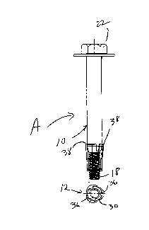
A sleeve bolt (A) for insertion in a hole
delimited by a wall comprises a threaded fastener
(10) and an expansion sleeve (12). The threaded
fastener (10) has a stem (14) that includes a
proximal cylindrical shank (16) and a distal threaded
section (18). The shank (16) has substantially the
diameter of the hole and defines at a distal end
thereof a conical expander portion (20). The
expansion sleeve (12) comprises a distal threaded
member (26) and a proximal expansion member (28), the
threaded member (26) being threadably engaged to the
threaded section (18) of the stem (14). The expansion
member (28) includes anchor legs (32) each having a
proximal end (38) adapted, upon axial displacement of
the expansion sleeve (12) towards the shank (16)
resulting from a rotation of the stem (14), to engage
the conical expander portion (20) such as to expand
the proximal ends (38) of the anchor legs (32) of the
expansion member (28) outwardly into engagement with
the wall. The expansion member (28) fractionally
engages the wall upon introduction of the stem (14)
in the hole.

Revendications

Note : Les revendications sont présentées dans la langue officielle dans laquelle elles ont été soumises.


CLAIMS:
1. A sleeve bolt for insertion in a hole delimited
by a wall, comprising a threaded fastener and an
expansion means, said threaded fastener having a
stem, said stem including a proximal stem section and
a distal threaded section, said proximal stem section
having substantially a diameter of the hole and being
provided at a distal end thereof with an expander
means, said expansion means being adapted to be
threadably engaged onto said distal threaded section
and having a proximal end adapted, upon axial
displacement of said expansion means towards said
proximal stem section resulting from a rotation of
said stem, to engage said expander means such to
expand outwardly into engagement with the wall.
2. A sleeve bolt as defined in claim 1, wherein
said expansion means comprise a distal threaded
member and a proximal expansion wedge, said threaded
member being adapted to be threadably engaged to said
threaded section of said stem, said expansion wedge
being adapted to frictionally engage the wall upon
introduction of said stem in the hole while said
threaded member is spaced from the wall such that,
upon sufficient subsequent rotation of said stem,
said expansion means displace towards said expander
means.
3. A sleeve bolt as defined in claim 2, wherein a
transversal size of said expander means reduces in
direction of said distal threaded section of said
stem such that, upon displacement of said expansion
wedge along said distal threaded section and towards
said expander means, a proximal end of said expansion
wedge engages said expandex means and gradually
expands outwardly.
7

4, A sleeve bolt as defined in claim 3, wherein
said expander means defines a taper.
5. A sleeve bolt as defined in claim 4, wherein
said expander means comprises a frusto-conical
portion.
6. A sleeve bolt for insertion in a hole
delimited by a wall, comprising a threaded fastener
and an expansion means, said threaded fastener having
a stem, said stem including a proximal stem section
and a distal threaded section, said proximal stem
section being provided at a distal end thereof with
an expander means, said expansion means being adapted
to be threadably engaged onto said distal threaded
section and having a proximal end adapted, upon axial
displacement of said expansion means towards said
proximal stem section resulting from a rotation of
said stem, to engage said expander means such to
expand outwardly into engagement with the wall.
7. A sleeve bolt as defined in claim 6, wherein
said expansion means comprise a distal threaded
member and a proximal expansion wedge, said threaded
member being adapted to be threadably engaged to said
threaded section of said stem, said expansion wedge
being adapted to frictionally engage the wall upon
introduction of said stem in the hole while said
threaded member is spaced from the wall such that,
upon sufficient subsequent rotation of said stem,
said expansion means displace towards said expander
means.
8. A sleeve bolt as defined in claim 7, wherein a
transversal size of said expander means reduces in
direction of said distal threaded section of said
stem such that, upon displacement of said expansion
wedge along said distal threaded section and towards
8

said expander means, a proximal end of said expansion
wedge engages said expander means and gradually
expands outwardly.
9. A sleeve bolt as defined in claims 7 and 8,
wherein said threaded member of said expansion means
comprises a conical section which tapers towards said
expansion wedge, said conical section being adapted,
upon sufficient rotation of said stem and once said
expansion wedge is substantially stationary onto said
expander means, to displace towards and relative to
both said expander means and said expansion wedge
such that said conical section causes a distal end of
said expansion wedge to expand outwardly into
engagement with the wall.
10. A method of setting a sleeve bolt in a hole
delimited by a wall, comprising the steps of: (a)
providing a threaded fastener and an expansion means
threadably engaged to a distal end of said fastener;
(b) inserting said expansion means and part of said
threaded fastener in the hole; (c) rotating
sufficiently said fastener with said expansion means
being fractionally engaged to the wall for causing
said expansion means to displace towards a proximal
end of said fastener and for causing a proximal end
of said expansion means to be expanded by said
fastener into engagement with the wall.
11. A method as defined in claim 10, wherein said
fastener has a stem, said stem including a proximal
stem section and a distal threaded section, said
proximal stem section having substantially a diameter
of the hole and being provided at a distal end
thereof with an expander means for expanding said
expansion means in step c), said expansion means
being adapted to be threadably engaged onto said
distal threaded section and having a proximal end
9

adapted, upon axial displacement of said expansion
means towards said proximal stem section resulting
from a rotation of said stem, to engage said expander
means such to expand outwardly into engagement with
the wall.
12. A method as defined in claim 11, wherein said
expansion means comprise a distal threaded member and
a proximal expansion wedge, said threaded member
being adapted to be threadably engaged to said
threaded section of said stem, said expansion wedge
being adapted to fractionally engage the wall upon
introduction of said stem in the hole while said
threaded member is spaced from the wall such that,
upon sufficient subsequent rotation of said stem,
said expansion means displace towards said expander
means.
13. A method as defined in claim 12, wherein a
transversal size of said expander means reduces in
direction of said distal threaded section of said
stem such that, upon displacement of said expansion
wedge along said distal threaded section and towards
said expander means, a proximal end of said expansion
wedge engages said expander means and gradually
expands outwardly.
14. A method as defined in claim 13, wherein said
expander means defines a taper.
15. A method as defined in claim 14, wherein said
expander means comprises a frusto-conical portion.
10

Description

Note : Les descriptions sont présentées dans la langue officielle dans laquelle elles ont été soumises.

CA 02270570 1999-04-30
SLEEVE ANCHOR
BACKGROUND OF THE INVENTION
1. Field of the Invention
The present invention relates to fasteners
and, more particularly, to expandable fasteners for
mounting to concrete structures, and the like.
2. Description of the Prior Art
Expandable anchors of many different types
are already known. More particularly, expandable
anchors have been developed for insertion into a hole
formed in a support structure such that an expansion
sleeve of the anchor may be selectively expanded into
frictional contact with the inside peripheral surface
of the hole such that the anchor becomes fractionally
anchored in the support structure. Typically, the
expandable anchor includes an elongated expander
member having a threaded first end and a flared
second end opposite the first end with a cylindrical
surface extending between the first and second ends
around which there is provided the aforementioned
expansion sleeve which generally has the shape of a
cylinder. The threaded first end is like a headless
screw and extends outwardly of the support structure
once the expandable anchor is positioned in the hole
thereof. A nut threaded on the visible part of the
threaded first end may be used as an actuating
mechanism with an object to be secured to the support
structure being typically located between the nut and
the support structure as the threaded first end of
the expandable anchor extends through this object.
By rotating the nut, it engages the outer surface of
the object and thus bears upon it such as to pull the
expander member in an outward direction. As the
expansion sleeve is already sufficiently fractionally
engaged with the inside surface of the hole, when the
expandable anchor is pulled by the rotation of the
1

CA 02270570 1999-04-30
nut, the expansion sleeve stays substantially
stationary in the hole and thus, as the expander
member is pulled out of the hole, the flared second
end of the expander member causes the radial
expansion sleeve to expand outwardly thereby
increasing a friction between the expansion sleeve
and the hole and thus securing the expandable anchor
therein.
Since the expansion sleeve must already be
fractionally engaged with the hole before the
expandable anchor is pulled, the outside diameter of
the expansion sleeve must be similar to the inside
diameter of the hole and even slightly greater
therefrom in order to ensure an initial frictional
contact therebetween which will then allow the
expansion sleeve to remain still in the hole while
the expander member is pulled outwardly thereof and
thus allow the expansion sleeve to be expanded by the
flared end of the expander member. This diameter of
the expander member, at rest, results in that the
expandable anchor when initially inserted in the hole
must be inconveniently driven with significant force
therein as the expansion sleeve is already
fractionally engaged with the inside wall of the
hole. The flared end acts as a wedge to expand the
expansion sleeve into greater frictional contact with
the inside of the hole.
Also known are undercut wedge anchors,
wherein the hole formed in the support structure is
enlarged at a distance from the visible opening of
the hole such that the expansion sleeve may be
inserted behind a shoulder defined at the junction of
the enlarged area and the remainder of the hole.
Once expanded, the expansion sleeve may abut this
shoulder and thus retain the anchor in position in
the support structure.
2

CA 02270570 1999-04-30
SUN~iARY OF THE INVENTION
It is therefore an aim of the present
invention to provide an improved expandable anchor
for use in holes in various materials, e.g. concrete.
It is also an aim of the present invention
to provide an expandable anchor, such as a sleeve
anchor, having an expander member and an expansion
member capable of spring-like deformation.
BRIEF DESCRIPTION OF THE DRAWINGS
Having thus generally described the nature
of the invention, reference will now be made to the
accompanying drawings, showing by way of illustration
a preferred embodiment thereof, and in which:
Figs. 1 to 3 are front elevational views of
a sleeve anchor in accordance with the present
invention shown respectively in first, second and
third positions thereof;
Figs. 4 to 6 are bottom plan views of the
expansion sleeve of the sleeve anchor of Figs. 1 to
3;
Fig. 7 is a top plan view of the sleeve
anchor of Figs. 1 to 3;
Figs. 8 and 9 are respectively front
elevational and top plan views of the fastener of the
sleeve anchor of Figs. 1 to 3;
Figs. 10 and 11 are respectively front
elevational and bottom plan views of the threaded
member of the expansion sleeve of the sleeve anchor
of Figs. 1 to 3;
Fig. 12 is a plan view of the expansion
member of the expansion sleeve of the sleeve anchor
of Figs. 1 to 3, this expansion member being shown in
its initial manufactured state, i.e. before being
shaped for use in the sleeve anchor;
Figs. 13 to 15 are respectively front
elevational and top and bottom plan views of the
3

CA 02270570 1999-04-30
expansion member of Fig. 12, but shown in its
position for mounting to the threaded member of Figs.
10 and 11;
Figs. 16 to 18 are respectively front
elevational, vertical cross-sectional and top plan
views of a second embodiment of the sleeve anchor of
Figs. 1 to 3, also in accordance with the present
invention; and
Figs. 19 to 21 are front elevational,
vertical cross-sectional and top plan views of the
home expansion sleeve of the sleeve anchor of Figs.
16 to 18.
DESCRIPTION OF THE PREFERRED EMBODIMENTS
In accordance with the present invention,
Figs . 1 to 3 illustrate a sleeve anchor A comprising
a threaded fastener 10 and an expansion sleeve 12.
The fastener 10 includes a stem 14 having a proximal
smooth cylindrical section 16, a reduced diameter
threaded distal section 18 and an intermediate
frusto-conical section 20. The fastener 10 also
includes a bolt head 22 and a washer 24 , both to be
located outside of the hole defined in a structure,
in which hole the stem 14 is to be inserted such that
an object may be held secure by the bolt head 22
against the structure.
The expansion sleeve 12 includes a
cylindrical internally threaded member 26 (Figs. 10
and 11 ) and an expansion member 3 0 (Figs . 12 to 15 ) .
The expansion member includes a central ring 30 and,
for instance, three anchor legs 32 extending
therefrom. When the threaded member 26 and the
expansion member 28 are assembled together as in
Figs. 1 to 6, narrow sections 34 of the legs 32 are
lodged in notches 36 defined on the periphery of the
threaded member 26.
4

CA 02270570 1999-04-30
The threaded section 18 of the fastener 10
is adapted to threadably mated with the threaded
member 26 of the expansion sleeve 12 with the
threaded section 18 extending through the central
ring 30 and with the legs 32 extending exteriorly
along the threaded section 18, as seen in a first or
inoperative position of the sleeve anchor A shown in
Fig. 1.
When the sleeve anchor A of Fig. 1 is
positioned in the aforementioned hole defined in the
support structure, the expansion sleeve 12
fractionally contacts the walls of the hole in a
sufficient manner such that the subsequent rotation
of the fastener 10 by way of its bolt head 22 will
cause the fastener 10 to move further into the hole
of the structure, as the expansion sleeve 12 remains
stationary in the hole (in view of its frictional
contact with the walls thereof) and in view of the
threaded engagement of the distal section 18 of the
fastener 10 with the threaded member 26 of the
expansion sleeve 12. Indeed, the rotation of the
fastener causes the same to displace through the
expansion sleeve 12 , whereby, as seen in Figs . 2 and
3, the expansion sleeve 12 is displaced relative to
the fastener 10 such that the legs 32 thereof climb
along the frusto-conical section 20 of the stem 14 of
the fastener 10 and are forced outwardly by the
frusto-conical section 20 until the proximal edges 38
of the legs 32 come into strong angled engagement
with the walls of the hole. The angle of the legs 32
in Fig. 3 and their engagement with the walls of the
hole prevent the anchor sleeve A from being forcibly
removed form the hole.
In Figs . 16 to 21 , a variant sleeve anchor
A' includes the same fastener 10 which is now used
with an expansion sleeve 12' having four legs 32'.
The expansion sleeve 12' is also of unitary
5

CA 02270570 1999-04-30
construction in that the threaded member and
expansion members 26 and 28 of the sleeve anchor A of
Figs. 1 to 15 are manufactured integrally with each
other.
6

Dessin représentatif
Une figure unique qui représente un dessin illustrant l'invention.
États administratifs

2024-08-01 : Dans le cadre de la transition vers les Brevets de nouvelle génération (BNG), la base de données sur les brevets canadiens (BDBC) contient désormais un Historique d'événement plus détaillé, qui reproduit le Journal des événements de notre nouvelle solution interne.

Veuillez noter que les événements débutant par « Inactive : » se réfèrent à des événements qui ne sont plus utilisés dans notre nouvelle solution interne.

Pour une meilleure compréhension de l'état de la demande ou brevet qui figure sur cette page, la rubrique Mise en garde , et les descriptions de Brevet , Historique d'événement , Taxes périodiques et Historique des paiements devraient être consultées.

Historique d'événement

Description Date
Le délai pour l'annulation est expiré 2004-04-30
Demande non rétablie avant l'échéance 2004-04-30
Réputée abandonnée - omission de répondre à un avis sur les taxes pour le maintien en état 2003-04-30
Demande publiée (accessible au public) 2000-10-30
Inactive : Page couverture publiée 2000-10-29
Lettre envoyée 2000-09-14
Inactive : Renseignement demandé pour transfert 2000-09-13
Inactive : Inventeur supprimé 2000-09-12
Inactive : Supprimer l'abandon 2000-09-08
Inactive : Abandon. - Aucune rép. à lettre officielle 2000-08-02
Inactive : Transfert individuel 2000-08-02
Inactive : Correspondance - Formalités 2000-07-31
Inactive : CIB en 1re position 1999-06-17
Inactive : Certificat de dépôt - Sans RE (Anglais) 1999-06-03
Exigences de dépôt - jugé conforme 1999-06-03
Demande reçue - nationale ordinaire 1999-06-02

Historique d'abandonnement

Date d'abandonnement Raison Date de rétablissement
2003-04-30

Taxes périodiques

Le dernier paiement a été reçu le 2002-04-30

Avis : Si le paiement en totalité n'a pas été reçu au plus tard à la date indiquée, une taxe supplémentaire peut être imposée, soit une des taxes suivantes :

  • taxe de rétablissement ;
  • taxe pour paiement en souffrance ; ou
  • taxe additionnelle pour le renversement d'une péremption réputée.

Veuillez vous référer à la page web des taxes sur les brevets de l'OPIC pour voir tous les montants actuels des taxes.

Historique des taxes

Type de taxes Anniversaire Échéance Date payée
Taxe pour le dépôt - générale 1999-04-30
Enregistrement d'un document 2000-08-02
TM (demande, 2e anniv.) - générale 02 2001-04-30 2001-04-11
TM (demande, 3e anniv.) - générale 03 2002-04-30 2002-04-30
Titulaires au dossier

Les titulaires actuels et antérieures au dossier sont affichés en ordre alphabétique.

Titulaires actuels au dossier
COBRA FIXATIONS CIE LTEE - COBRA ANCHORS CO. LTD.
Titulaires antérieures au dossier
LANG NGUYEN
PIERRE R. MCDUFF
Les propriétaires antérieurs qui ne figurent pas dans la liste des « Propriétaires au dossier » apparaîtront dans d'autres documents au dossier.
Documents

Pour visionner les fichiers sélectionnés, entrer le code reCAPTCHA :


Pour visualiser une image, cliquer sur un lien dans la colonne description du document. Pour télécharger l'image (les images), cliquer l'une ou plusieurs cases à cocher dans la première colonne et ensuite cliquer sur le bouton "Télécharger sélection en format PDF (archive Zip)" ou le bouton "Télécharger sélection (en un fichier PDF fusionné)".

Liste des documents de brevet publiés et non publiés sur la BDBC .

Si vous avez des difficultés à accéder au contenu, veuillez communiquer avec le Centre de services à la clientèle au 1-866-997-1936, ou envoyer un courriel au Centre de service à la clientèle de l'OPIC.


Description du
Document 
Date
(aaaa-mm-jj) 
Nombre de pages   Taille de l'image (Ko) 
Dessin représentatif 2000-10-24 1 4
Description 1999-04-30 6 226
Dessins 1999-04-30 3 74
Abrégé 2000-07-31 1 30
Revendications 2000-07-31 4 169
Page couverture 2000-10-24 1 36
Certificat de dépôt (anglais) 1999-06-03 1 165
Demande de preuve ou de transfert manquant 2000-05-02 1 109
Courtoisie - Certificat d'enregistrement (document(s) connexe(s)) 2000-09-14 1 120
Rappel de taxe de maintien due 2001-01-03 1 112
Courtoisie - Lettre d'abandon (taxe de maintien en état) 2003-05-28 1 176
Rappel - requête d'examen 2003-12-31 1 123
Correspondance 1999-06-07 1 37
Correspondance 2000-07-31 7 291