Note: Descriptions are shown in the official language in which they were submitted.
CA 02270613 2004-11-03
1
PACKAGING FOR SMOKING ARTICLES
This invention relates to packaging for smoking articles
such as cigarettes, cigars and cigarillos. For convenience and
brevity these will be referred to herein as cigarettes.
The present invention provides packaging for cigarettes
which acts as an effective barrier against ingress and egress of
humidity or ingress of contaminants during transport and storage
of the packaged cigarettes, but which also allows maintenance of
that effective barrier property even after the package has been
first opened by the user. In other words, we are providing a
resealable barrier layer in cigarette packaging.
The provision of barrier layers either as an inner wrap of a
cigarette carton or an outer wrap or both is commonplace.
Provision is more or less essential if cigarettes are to have any
sort of commercial shelf life in zones having hostile climatic
conditions, especially in high temperature, high humidity zones.
But as far as we are aware all such barrier layers so far
provided, whether internal or external, have been destroyed in
their barrier function when the user first opens the package.
Typically, an outer barrier layer has a tearstrip which the user
operates to separate halves of the outer wrap which is then
discarded, or a barrier layer within a cigarette carton (or
surrounding a soft wrap package) although not usually discarded
CA 02270613 2004-11-03
2
once the package is opened has a permanent opening formed in it
by the user when he first gains access.
US-A-4763779 shows a tin-foil inner wrapping for a Laube-
type box where a flap of that wrapping may be brought down over
an access aperture, and overlap the edges of the aperture. It
may have a "peel-seal" connection to the edges it overlaps.
US-A-5333729 shows in Figures 11 and 12 a tab which when
lifted towards a side wall tears an overwrap. The tab may have a
tacky surface to reclose the hole opened in the overwrap.
US-A-5511658 shows a pack with a folding lid the front wall
of which is extended to overlap over a major face of the pack in
order to reclose the pack by attachment to a spot of glue.
The present invention provides a pack of smoking articles
having two major faces, two side walls and two end walls, said
pack comprising: a sealed enclosure comprising a barrier layer,
around a charge of smoking articles, the barrier layer having
corresponding two major face, two side walls and two end walls, a
smoking article removal access aperture being defined in the
barrier layer, said aperture extending from a top end wall into
one of said major faces of said barrier layer and there extending
over said aperture, and extending beyond all of the edges
thereof, a cover layer adhesively bonded to said barrier layer
and comprising a permanently tacky undersurface engageable with
CA 02270613 2004-11-03
2a
said barrier layer adjacent to said edges of said aperture beyond
said aperture, whereby, after opening of said aperture, said
enclosure can be resealed by re-engaging said permanently tacky
surface with said barrier layer adjacent to said edges beyond
said aperture; and a frame inside said enclosure and outside said
charge, said frame comprising at least a major panel, which major
panel is at said one of said respective major faces of said pack,
two side panels at respective side walls of said pack and top
flap means at respective ends of said top end wall of said pack,
edge portions of said major panel and said top flap means of said
frame providing reaction surfaces against the resealing pressure
exerted adjacent to said edges of said aperture, when said cover
layer is brought into resealing re-engagement with said barrier
layer.
In the present invention we provide a resealable sealed
barrier layer by defining in the barrier layer an access aperture
extending from an end wall into a major face of a cuboid pack,
there being over the aperture and extending beyond all of its
openable edges a cover layer having a permanently tacky surface
engageable with the barrier material adjacent to the edges of the
aperture. The cover layer will usually be a discrete layer
applied to the barrier layer.
The aperture may be defined by lines of weakening in the
unopened package, not penetrating through the thickness of the
CA 02270613 2004-11-03
2b
material, or by actual cuts, with or without interruptions. The
aperture in the barrier layer will preferably be defined by the
CA 02270613 2004-11-03
3
line or lines of weakening or cuts and by an unweakened or uncut
edge, this forming a hinged flap of the barrier material.
The cover layer with a permanently tacky surface may itself
be formed of barrier material, even if discrete from the main
body of such material, but it may be quite satisfactory to use
for that purpose a paper or other sheet material which
preferably will be continuous from edge to edge, that is to say,
across the whole extent of the aperture in the barrier layer
plus its overlapping edges.
The layer may be in the form of a label, a coupon or an
excise stamp, for example.
The preferred material of the barrier layer will either be
a plastics/metal foil laminate or a metallized plastics material
since either of these offer outstandingly good barrier
properties.
The barrier layer may be continuous over one minor end of
the pack or charge, and have side seams along both minor sides
of the pack and an envelope or similar fold over the opposite
minor end. The barrier layer need not be applied in that manner
- it can equally well be applied so as to be continuous over one
minor side and sealed over both minor ends and one minor side.
Various patterns of heat sealable portions of barrier
layer, achieved by the application of glue, lacquer or the like
to the barrier material, can when heat-sealed with each other or
CA 02270613 2004-11-03
4
with the barrier material form an enclosure which is as near as
possible hermetic.
It is desirable that a non-adhesive tab is present at one
edge of the cover layer, to aid opening and reopening of the
pack.
It is preferable that the tab does not lie flush with the
barrier layer, so that it may be more easily gripped when
opening/reopening the pack. This may be achieved by various
means, for example by folding in the region where the tab joins
the adhesive portion of the cover, by applying inks or other
media which upon drying distort the material of the cover, or by
distorting the cover by embossing. More preferably, the tab is
folded back to lie against (the non-adhesive surface of) the
cover and then releasably held in place by minor amounts of an
adhesive.
A resealable pack may be included in a Laube, or flat, box.
Such boxes are well known in the art and are generally rigid,
being made of thick card or similar material, and hinged along a
minor edge of a major face, or along a major midline of a minor
face. In such embodiments, the aperture in the barrier layer is
preferably located on the front surface of the pack (that is,
the major surface that is revealed when the Laube box is opened)
and the top surface (that is, the surface which is furthest from
the hinge of the Laube box). It may be desirable for the cover
to have a tab at the top of the pack, which tab may be arranged
CA 02270613 2004-11-03
to protrude between the lips of the Laube box. The barrier
layer may be placed around the bundle of cigarettes either to
produce a side-seamed enclosure or one seamed over the front
and/or back major faces of the bundle.
Furthermore, flavourant may be provided in the permanently
tacky adhesive used for resealing the barrier layer. Thus, a
quantity of the flavourant will be released each time the
cigarettes are accessed. This contrasts with previously known
systems (such as described in US-A-5249676) which release only a
single burst of flavourant, on initial opening of the packaging.
In the present invention, the flavourant is preferably
micro-encapsulated, each action of disengaging the tacky surface
from the barrier layer causing a proportion of the micro-
capsules to be ruptured, and so release their contents. US-A-
4720423, again relating to a one-off flavourant release system,
describes how flavourant-bearing micro-capsules may be
incorporated into adhesive.
By flavourant is meant any substance which releases,
produces, neutralises, masks or alters odours, for example a
perfume or deodorant.
Flavourant may alternatively or additionally be
incorporated into an integer which is included within the
cigarette packaging, inside the barrier layer. The integer may
be of a porous substance, for example a pad, a paper sheet or
may be the card inner frame of a semi-rigid pack.
CA 02270613 2004-11-03
6
Alternatively, the flavourant may be encapsulated or included in
a sachet, the capsule or sachet being included within the
packaging.
This flavourant may permeate the cigarettes included within
the packaging, so as to affect the taste or odour of smoke
produced when smoking the cigarettes. A preferred such
flavourant is menthol.
Flavourant may be incorporated into both a resealable
adhesive layer (outside a barrier layer) and an insert (inside
the barrier layer). The flavourants may be the same, so that
their effects reinforce, or different, for example to provide
one flavour on opening the packaging and a different flavour in
the cigarette.
We also disclose an inner frame particularly suitable for
the resealable packaging of this invention. Such an inner frame
has panels which are foldable relative to each other to form
four at least partial faces of a cuboid including one major
face, and additionally has flap means comprising a flap or flaps
which forms) an incomplete fifth face of the cuboid.
In a preferred configuration, the frame has a major panel,
two elongate side panels and a (bottom) end panel, and flap
means comprising two flaps. The long edges of the side panels
and the end panel are the major edges and a minor edge,
respectively, of the major face. The flaps are at the top ends
of the side panels. Thus, upon folding, the frame forms a major
CA 02270613 2004-11-03
7
face, two long side faces and a bottom end face of a cuboid,
with the flaps forming two parts of an incomplete top end face.
It is preferable that the major face is not a complete
rectangle, but has a recess in the top edge. When such a recess
is present, it is further preferable that the end panel is
shaped so that two blank, unfolded, frames placed end-to-end
tessellate ( i . a . can lie next to each other without overlaps or
gaps) thus minimizing the amount of material needed.
The aperture in the barrier layer through which cigarettes
may be accessed preferably overlies the region between the flap
means comprising a flap or flaps and the recess in the major
panel of the frame. The flap means, being supported on any
cigarettes remaining in the pack (because it is preferable that
the length of the side edge is similar to that of the
cigarettes) , provides an anvil which supports the barrier layer
adjacent the aperture, allowing the adhesive cover to be pressed
firmly against the barrier layer, to aid resealing.
Of course, inner frames may have single folds between the
panels (producing sharp edges) or double folds (producing
bevelled edges). Alternatively, the sides of the frame may be
rounded, for example to be used in a so-called "oval" pack.
The present invention is not limited to single bundles of
cigarettes. For example, multiple bundles may be enclosed in
the resealable barrier material and then inserted together into
a single outer shell. Alternatively, multiple bundles, each
CA 02270613 2004-11-03
8
within an inner frame, may be overwrapped together in a single
pack-forming sheet, to form a semi-rigid pack containing
multiple bundles.
Flavourant may be added to the packaging in the form of so-
called "scratch and sniff" panels. That is, the flavourant may
be coated on the packaging in a form (for example micro-
encapsulated) which allows release of the flavourant when
abraded. Such scratch and sniff panels are well known, for
example in magazine advertisements for perfume.
The seams of the barrier layer may be formed using glue or
heat-sealable strips which are added to the barrier layer for
example, by being printed on. This finds particular
applicability when the barrier layer is a metal/paper laminate
or metallized paper. However, one or more external faces of a
plastics laminate or foil may be of heat-sealable material.
Various embodiments of the invention will now be described
with reference to the accompanying drawings, wherein:
Figure 1 is a perspective view of a generalised embodiment
of the invention;
Figure 2 shows an inner frame of a first embodiment;
Figure 3 is a diagrammatic end view of the inner frame of
Figure 2 assembled around a charge of cigarettes;
Figure 4 is a plan view of a barrier layer and label to be
wrapped around the inner frame of Figure 2 together with its
charge of cigarettes;
CA 02270613 2004-11-03
9
Figure 5 is a view from behind and below of the packaging
formed by that first embodiment;
Figure 6 is a face view of the inner frame of a second
embodiment;
Figure 7 is a diagrammatic end view of the inner frame of
the second embodiment assembled around a charge of cigarettes;
Figure 8 is a plan view of the barrier layer of the second
embodiment;
Figure 9 is a view from behind and below of a packaging
formed by the second embodiment;
Figure 10 is a plan view of a label of the second
embodiment;
Figure 11 indicates the assembly of that label with a top
view of the barrier layer of the packaging;
Figure 12 shows the inner frame of a third embodiment;
Figure 13 show a barrier layer for that third embodiment;
Figure 14 is a face view of a label for the third
embodiment and Figure 15 shows an assembly of that label with a
top view of the packaging of the third embodiment;
Figures 16 and 17 show respectively face and assembled view
of fourth forms of label;
Figure 18 shows a fourth and preferred embodiment of inner
frame;
Figure 19 shows the fourth embodiment made up, with end
flaps to act as anvils against resealing pressure.
CA 02270613 2004-11-03
Figure 20 shows a fourth embodiment of cut blank of barrier
material;
Figure 21 shows a front view of the fourth embodiment when
made up into a container;
Figure 22 shows a top plan view of the fourth embodiment
when made up into a container, with a small portion cut away;
Figure 23 shows one side view of the fourth embodiment when
made up into a container;
Figure 24 shows the other side view of the fourth
embodiment when made up into a container;
Figure 25 shows a fifth embodiment of cut blank of barrier
material;
Figure 26 shows a front view of the fifth embodiment when
made up into a container;
Figure 27 shows a top plan view of the fifth embodiment
when made up into a container, with a small portion cut away;
Figure 28 shows one side view of the fifth embodiment when
made up into a container;
Figure 29 shows a second side view of the fifth embodiment
when made up into a container;
Figure 30 shows heat-sealable areas on an inner face of a
barrier blank; and
Figure 31 shows heat-sealable areas on an outer face of a
barrier blank.
CA 02270613 2004-11-03
11.
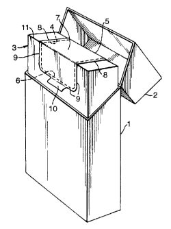
Figure 1 shows a general embodiment with a rigid card pack
1 with a "flip-top" lid 2 containing a package 3 comprised of a
charge of cigarettes overwrapped in a barrier layer. The bounds
of an aperture for allowing access to the cigarettes are
indicated by parallel dotted lines 4 extending from the rearside
of the package 3 where a hinge line is formed on the edge 5
across the top of the package and down the front as far as a
third line 6 parallel to the hinge line on edge 5. As will be
seen and as is clearly apparent other shapes of that aperture
are possible; furthermore the hinge line of the lid need not be
at the back of the package 3. The barrier layer which forms the
package 3 may be made for example of metallized plastics or of a
plasticsJmetal foil laminate. Over its aperture lies an
element, here in the form of a label 7, which is a layer of
material having on its undersurface nearer to the barrier layer
a permanently tacky material. The permanently tacky material
may cover continuously or intermittently the whole of that
undersurface, or a permanent bonding adhesive may be on the
portion of the undersurface which does not overlie the edges of
the barrier layer, but where the label 7 extends at edges 8 and
9 beyond the aperture edges 4 and 6 the undersurface must be
provided with that permanently tacky material.
Beyond one edge of the label 7 is a tab 10 which is at
least partly free of the permanently tacky material so that it
CA 02270613 2004-11-03
12
may be flicked up by the user and used to pull the label to open
the package.
On first use, the aperture edges 4 and 6 may have been
defined by lines of weakening in the barrier layer or by actual
cuts. If by cuts, there preferably will be interruptions, for
example aligned with front corner 11 of the package and/or in
the corners between edges 4 and 6 of the aperture, so that on
first lifting of the tab 10 the user feels that a separating
action has occurred. The user is then free to remove cigarettes
from the package through the aperture and after having done so
may reseal the aperture simply by bringing down the tab 10 so
that the edges 8,9 re-adhere to the adjacent portions of the
barrier layer. The flap of barrier layer formed by the
separation along those lines when the tab 10 was lifted is
returned to its previous position and although there will now be
a line of separation in that barrier layer it is covered by the
adhered edges 8,9 of the label.
To ensure as far as possible efficient adhesion_an inner
frame within the package offers a reaction surface underneath
the barrier layer against the resealing pressure exerted on
edges 8 and 9.
In the embodiments described the package 3 is a separate
entity removable from the outer carton. The latter may be of
any suitable type and in particular may be of the so-called
"shell and slide" type wherein the package may be pressed from
CA 02270613 2004-11-03
13
one end of the carton to protrude from the other for the purpose
of exposing cigarettes for more ready access by the user.
Furthermore, the package above, and those to be described,
may any of them be an independent entity, that is to say, may be
sold without a rigid carton surrounding them, at least if,
preferably, means such as a conventional clear celluloid
overwrap were provided to provide further protection and prevent
accidental disturbance of the tab 10. The resealable barrier
layer may also be over a rigid carton.
Specific embodiments both of frames and of resealable
barriers will now be described with reference to the remaining
drawings. Any of these embodiments can be used in any of the
contexts mentioned above and (in principle) with any other of
them.
In Figure 2 we see an inner frame 15 of card which has a
front panel 16, two side panels 17 and top flap means 18
comprising a top flap further comprising regions 18a and 18b.
Score or fold lines 19,20 form corners as seen in Figure 3 when
the panels 17 are folded to right angles with the panel 16. Top
flap 18 is also folded to right angles. It can be seen that
when the inner frame has been folded for assembly in that way
there is an aperture 21 formed through which most of the charge
22 of (here) twenty cigarettes will be accessible as
diagrammatically indicated in Figure 2. The aperture 21 extends
to a base edge 23 in the front panel.
CA 02270613 2004-11-03
14
Figure 4 is a face view of a sheet 25 which is to form a
barrier layer overwrapped around the charge of cigarettes
contained in the inner frame 15. Fold lines 26 show where the
sheet will be brought round to overlie side panels 17 of the
frame and dotted lines 27 show where it will be brought round to
overlie the top flap 18. At the bottom of the package formed
around the inner frame and its charge (an operation which can be
carried out on standard machines?, and adjacent the top of the
package diamond folds 28,29 axe formed as indicated in Figure 5,
and this and side seams are sealed in any suitable manner, as
for example in reciprocating, sliding, tractor or band- or
induction-sealing mechanisms.
An aperture in the barrier layer is defined by slits 30,31.
There is a discontinuity between these slits at 32. The slits
30,31 which are pre-cut through the whole thickness of the
barrier material correspond to the side edges of the aperture 21
in the inner frame and to its base edge 23 in the front panel
respectively. On the line 27 a hinge portion 33 is formed in an
uncut area.
To maintain the flap formed by the cuts 30,31 securely in
position and to prevent all but negligible transfer of humidity
through the barrier, a layer 34 is applied over the aperture
formed in the barrier layer. This is in the form of a label,
usually of a film of plastics material, of which the
undersurface is coated with a permanently adhesive, that is to
CA 02270613 2004-11-03
say a permanently tacky, material so that it adheres to the
barrier layer and can readhere to it. In this embodiment the
label extends beyond all edges of the aperture i.e. both those
formed in the barrier layer by slits 30,31 and that formed by
the hinge 33, by marginal portions 35 on the sides, 36 on the
bottom and 37 on the back respectively. If the slots 30 were to
terminate short of line 27 it would not be necessary for portion
37 to be on the back of the package.
Beyond the portion 36 is a tab 38 which is free of the
adhesive material.
As can be seen the package once made up can be inserted
into a carton and used in a manner generally described in
relation to Figure 1. When the user first lifts the tab 38 he
should get a distinct signal as the discontinuities 32 are
severed for the first time. When he has extracted one or more
cigarettes he can reseal the package by applying the edge
portions 35 and bottom portion 36 once more to the surrounding
barrier material, with edge portions of the frame 15 around the
aperture 21 acting as an anvil against the pressure exerted.
Provided that the barrier layer is correctly repositioned,
something which is assisted by the hinge portion 33, the
integrity of the barrier layer after opening and resealing
should be as good as it was before.
In the second embodiment as seen in Figures 6-11 an inner
frame 15' is dimensioned for a smaller charge 40 of cigarettes,
CA 02270613 2004-11-03
16
here ten, but is in other respects identical to inner frame 15.
Like parts have been given like reference numbers and do not
need further description.
The barrier layer used in the second embodiment is however
different in detail, though identical in function. The sheet 41
in Figure 8 is to be folded integrally around the base of the
inner frame and charge and to be sealed only at its sides and
top. It has front and back forming panels 42, lines 43
indicating where the barrier layer will turn around the base of
the charge as indicated in Figure 9.
Lines 44 indicate where side panels 45 are defined which
will be sealed together in a seam up each side of the formed
package.
As the layer is brought around the package line 47 overlies
and is brought into register with line 46, with lines 48 and 49
indicating the position of turn around the front and the back
edges respectively of the top of the charge.
An aperture in the barrier layer is formed by a slit 50 in
the shape of a narrow-mouthed U the legs of which extend just
across line 47. There may be discontinuities in the slit such
as discontinuity 32 described with reference to the first
embodiment. Discontinuous slits 51 cross the line 46. The
distance between slits 51 is different from that between two
parallel portions of slit 50 where the two will overlie in the
assembled package (see Figure 11). This avoids a need for exact
CA 02270613 2004-11-03
17
registration of slits in the respective ends of the sheet when
they are brought together in the wrapping and sealing operation.
In the front panel-forming portion 42 of the laminate the
aperture defined by the slit 50 widens and parallel portions 52
correspond in position to the edges 21' of the aperture in the
inner frame 15'.
A label 55 of paper (Figure 10) has an undersurface which
is permanently tacky and has a base part 56 which covers over
most of the upper surface of the package.
A flap part 57 of the label 55 extends over and beyond the
edges of the flap defined by the slit 50 in the barrier layer,
providing edge portions 58, 59 and 60 for adhesion to the
adjacent parts of that barrier layer as indicated in Figure 11.
As in the first embodiment there is a tab 61 free of tacky
material, to assist the user's handling and resealing of the
formed package.
In a third embodiment seen in Figures 12 to 15, the inner
frame seen in Figure 12 is identical with inner frame 15 of
Figure 2 and will not be described further.
Sheet 65 seen in Figure 13 is very similar to sheet 41 of
Figure 8 but a different conformation of slit and hence of
aperture is shown. Here, an aperture for the package to be
formed by this sheet is defined by parallel straight line slits
66 traversing lines 47' and 49' and which after an interruption
67 are continued into a base slit 68; the slits together
CA 02270613 2004-11-03
18
defining a flap openable on a notional hinge formed by the label
(Figure 14) in the region behind lines 46'. Interrupted slits
51' traverse line 46' and are at a different spacing from lines
66.
The label seen in Figure 14 is assembled to the formed
package the top of which is shown in Figure 15: front and rear
flaps of the package are sealed together in the region 69 to
form effectively a single flap. An inner frame top flap (if
provided) could be adhered to the barrier layer. In
conformation and function the label is similar to the label
described with relation to Figures 10 and 11 and is designated
55'.
Figures 16 and 17 show a further conformation of label 70
suitable for any of the embodiments so far described in which,
instead of a base portion such as 56 or 56' in Figures 10 or 14,
the flap here 71 which is to cover over and ext end beyond the
aperture-forming portion of the barrier layer is except for its
non-tacky flap 72 flanked on both sides as well as in its hinge
region by permanently tacky label material 73,74.
Labels such as those shown in Figures 10, 11 and 14-17 may
have interruptions in the slits defining their flaps so as to
provide a tamper-indicating function. Such interruptions may
also assist in machine feeding of the labels.
Figures 18 and 19 show an inner frame usable with any form
of barrier layer described and has the advantage of two end
CA 02270613 2004-11-03
19
f laps on the top face . An inner frame 101 as shown in Fig . 18
is formed from a blank sheet of stiff card or similar foldable
material. A major panel 102, which is generally rectangular,
has elongate rectangular side panels 104 extending from the two
major edges 106, the long edges of the side panels being co-
extensive with the major edges 106. A generally rectangular end
panel 108 extends from a minor edge 110 (the "bottom" edge) of
the major panel 102, the long edge of the end panel 108 being
co-extensive with the aforesaid bottom edge 110. At the top
ends of the side panels 104 are small rectangular flaps 112
(which form top flap means), which are effectively continuations
of the side panels 104, along the top edges 114 of the side
panels 104.
Figure 19 shows the inner frame folded inwardly along lines
106, 110, 114, the panels 102, 104, 108 then forming four faces
of a cuboid, and the two flaps 112 forming two ends of an
incomplete fifth face.
The major panel 102 is not a complete rectangle, it having
a recess in its top edge. The bottom panel 108 is shaped to
match the recess, so that, as can be seen from Figure 18, two
unfolded frames laid end-to-end would tessellate.
In the resealable semi-rigid pack the major panel 102 is at
the front of the pack, with the aperture for cigarette access in
the barrier layer overlying the recess in the major panel 102
and the gap in the top face between the two flaps 112. The two
CA 02270613 2004-11-03
flaps 112, when supported by cigarettes remaining in the pack,
provide an anvil against which the adhesive cover (labels of the
resealable barrier layer may be pressed to ensure good
resealing. The length of the major edges of the major face of
the major panel 102 is similar to that of the cigarettes to be
contained, so that end cigarettes support, and may be gently
squeezed longitudinally by, those flaps by virtue of the latter
being wrapped by the barrier layer.
A flavourant-bearing integer can be included inside the
barrier layer, for example a sachet, capsule or porous sheet.
Alternatively the inner frame can be made of card on which is
coated or in which is included a flavourant, e.g. menthol.
Microcapsules bearing flavourant can be included in the
permanently tacky adhesive so that flavourant is released each
time the cigarettes are accessed. A suitable adhesive is
available from Sessions of York, Huntington Road, York Y03 9H5,
England.
Figure 20 shows a cut blank for forming a barrier seal
around a charge of smoking articles, usually contained in an
inner frame. This blank is generally applicable in all the
situations envisaged above and may be made of any of the
materials mentioned there, but differs in that it is designed to
be applied by folding around one minor side edge of the charge
and of any inner frame rather than around one minor end.
CA 02270613 2004-11-03
21
The blank of Figure 20 has major panels 201 and 202 which
are respectively to be front and rear panels of the made-up
package. An intermediate panel 203 will be continuous over one
of the minor side edges of the charge. End panels 204 and 205
will overlie each other on the other of the side edges of the
charge and will be heat sealed together in a seam.
To one edge of panels 201 to 205 are respective end flaps
206 and 207 on the major panels and gussets 208, 209 and 210 on
the minor panels. First, end panels 206 and 207 are folded in
and gussets 208, 209 and 210 are then folded out. The end
panels and gussets are then sealed, usually, as with the side
seam between panels 204 and 205, by heat sealing, and then the
gussets are tucked to lie along the side panels, where they may
be tacked in position.
At the other edge of the panels 201 to 205 are other end
flaps and gussets 210' to 214 respectively which correspond
generally to flaps and gussets 206 to 210' but which, in flaps
210' and 211, are slit so as to form an openable access flap for
the user of the pack to gain access to its contents.
Flap 210' is interrupted by parallel cuts 215 which start
just short of the free edge of the flap and extend into the main
front panel 201 to a narrow bridge 216. A U-shape cut 217
extends from one bridge to the other in the main panel 201.
CA 02270613 2004-11-03
22
In end flap 211 parallel cuts 218 extend to the potential
fold line which divides panel 202 from flap 211 being there
brought round in a J form at 219.
Adjacent to the extreme edge of the flap 211 are bridges
220 and beyond bridges 220 short final cuts 221 co-linear with
cuts 218 and extending to the free edge of the flap 211.
Figure 21 shows how the main panel 201 and the cuts 215 and
217 and bridges 216 may appear when the pack is made up. Of
course, since the pack is resealable the cuts will not be
visible since they will be overlaid by the resealable
permanently adhesive layer (label). Furthermore, the pack may
be contained within an outer carton of any suitable type and/or
be overwrapped.
Figure 22 shows a top view of the barrier enclosure when
made up around a charge, flap 210' having been heat sealed in
the region 222 over flap 211. It can be seen that the spacing
apart of cuts 215 is slightly greater than that of cuts 218 so
that they do not coincide in the made-up pack, there thus being
continuity of barrier action. Flap 210' has been cut away
somewhat to show the position of bridge 220 between cuts 218 and
221.
Figure 23 shows a side seam heat sealed region 223 between
side flaps 204 and 205, with gussets 209,210,213,214 forming
folds 224, 225 at the top and bottom ends of that minor edge of
the pack.
CA 02270613 2004-11-03
23
The opposite minor edge as seen in Figure 24 shows the
continuity of the barrier material over that edge and grocer's
folds 226,227 formed by gussets 208 and 212.
In the fifth embodiment of blank, seen in Figures 25 to 29,
different folding means are provided, giving a cleaner effect to
the side walls of the made-up pack but somewhat restricting the
width available for the formation of an access flap.
In this embodiment blank main panels 230 and 231 are front
and back panels respectively and are linked by side panel 232
which is to extend continuously over one minor side edge of the
charge of smoking articles and any inner frame. In the made-up
pack panels 233 and 234 overlap and are sealed to each other on
the opposite minor side edge.
End flaps 235 to 239 are respectively joined to panels 230
to 234 with potential fold lines being indicated in dotted
lines. In particular, diagonal fold lines 240 interrupt the
more major of the end flaps, -namely flaps 235 and 236.
At the other edge of the main panels 230 to 234 are end
flaps 241 to 245 respectively corresponding generally to flaps
235 to 239, and with fold lines 246 corresponding generally to
fold lines 240.
However, as in the fourth embodiment, the major end flaps
241 and 242 are interrupted by cut lines which are to define an
access flap into a sealed enclosure formed by this blank around
a charge of cigarettes. Cuts 247 run parallel across flap 241
CA 02270613 2004-11-03
24
from closely adjacent its free edge into the main panel 230 to
pips 248 (otherwise referred to herein as interruptions or
bridges) from one to the other of which runs a U-shaped cut 249
in the main panel.
On end flap 242 are J-shaped cuts 250 extending from near
the free edge of the flap to its potential fold line with panel
231, and leading to bridges 251 adjacent to which short cuts 252
lead to the free edge of the flap.
Figure 26 shows a front view of the blank of Figure 25 made
up to a package (otherwise referred to herein as a pack), and
Figure 27 a top view of the package where it is to be noted that
cuts 247 and 250 do not coincide, although in contrast to the
fourth embodiment cuts 250 are further apart than are cuts 247.
The drawing has a small relief in flap 241 so that a bridge 251
in a cut 250 can be seen.
Figure 28 shows the side seam 253 formed between panels 233
and 234 and Figure 29 shows panel 232 on the other minor side of
the charge. The clean effect on the sides can be noted, this
being due to the formation of folds only on the top and bottom
minor ends of the package.
Further embodiments of barrier layer blank are seen in
Figures 30 and 31. The outline of these is schematic only -
they may, for example, be any of the specific forms of blank
described above, where the barrier is continuous over one minor
CA 02270613 2004-11-03
end of the charge and inner frame, and an actual or potential
access aperture will be formed in them.
In Figures 30 and 31 major panels 260,261 are joined by
base panel 262 and lead to top flaps 263,264. Side and corner
flaps 265 to 269 are disposed along each side of the panels and
flaps 260 to 264.
Cross-hatching shows areas 270 on the face (Figure 30)
destined to be inner and 271 (Figure 31) on the face destined to
be outer in the made-up .pack, which are areas of heat-sealable
lacquer or glue; alternatively heat-sealable areas of a plastics
composition of the barrier material itself complement each other
to form a continuous seal around all seams and folds of the
sealed barrier enclosure.