Note: Descriptions are shown in the official language in which they were submitted.
CA 02271009 1999-OS-OS
wo 9snsia.~ ~cr~rs9~m6a,~
METHODS AND APPARATUS FOR FULL ~N(DTH ULTRASONIC BONDING
FIEr D OF T'riE INVENTION
The present invention relates to methods and apparatus fcr ~cnding webs to
eac:v other.
More particularly, the invention relates to ultrasonic bonding cf webs using
multiole
ultrasonic hums and an anvil.
t0 2ACicG~OUND OF T'?-!E INVEV i 10N
Ultrasonic benders are i<ncwn in the art. Staocnary piunce-ncm ultrasonic
bcneers are
~imctec to operating on weos traveling at Icw saes=s because. among other
reascns, at
higher web speeds, the web being ooerateo cn tents ;o ails uo, or ~unc.7 up.
at the
1 ~ leasing loge cf the plunge-type stationary ultrasonic ncm.
U.S. Patent 3.379.Z~o to Rust. Jr. disGoses acoaratus :cr welcinC
thermoplastic sneet-
(ike erements wherein rNO rows of stationary uttrascnrc plunge- type noms.
backed uo by
an anvil. in ~mbination, produce a bonoeo fabnc. The anvil has orolec7ons
which form a
20 pattern on the sheet-like elements.
U.S. Patent 3.844,869 to Rust. Jr. disGosas similar apparatus for joining
sheets of
thermoplastic material by ultrasonic vibration. However, a single stationary
ultrasonic
resonator extends across the width of the sheets. The single ultrasonic
resonator applies
25 ultrasonic energy to join the respective sheets to one another.
SUBSTITUTE SHEET (RULE 26)
CA 02271009 1999-OS-OS
WO 98I28123 PCT/US97/21623
U.S. Patent 4,414,045 to Wang et al discloses apparatus for forming non-woven
fabric
from a batt of random, loose, fibers, using stationary ultrasonic horns as the
mechanism
for consolidating the fibers into the fabric. Respective arrays of ultrasonic
horns extend
across the path of advance of the batts, and overlie corresponding anvils
spaced
longitudinally along the path of advance of the batts. Column 6, lines 33-37
recites
operating the apparatus at a web speed of about 150 meterslminute) calling
such speed a
"high speed." Typical production speed is described at column 1, fines 47-55
as
10-30 meterslminute.
SUMMARY OF THE DISCLOSURE
The present invention relates to methods and apparatus for fabricating webs,
including
composite multiple-layer webs, and focuses on forming such webs by ultrasonic
bonding
applied across the widths of webs or web precursors, in some embodiments
across the
entirety of the common width of multiple webs or web layers.
In a first family of embodiments, the invention comprehends methods of
fabricating a
composite web having a length and a width. First and second webs are disposed
in
surface-to-surface relationship with each other. Each web comprises first,
second. third
and fourth segments. Each segment of each web comprises a separate and
distinct part
of the width of the respective web, and extends along substantially the entire
length of the
respective web. The segments m each web are substantially parallel with
respect to eac~
other. The first and second webs are brought into surface-to-surface alignment
with an
anvil roll. First and second rotary ultrasonic horns are applied to the webs,
ultrasonically
bonding the first segment of the first web to the first segment of the second
web, on the
anvil roll at a first location between the anvil roll and the first rotary
ultrasonic hom. and
bonding the third segment of the first web to the third segment of the second
web at a
second location angularly spaced about an axis of the anvil roll from the
first location.
Third and fourth rotary ultrasonic horns are applied to the web,
ultrasonically bonding the
second segment of the first web to the second segment of the second web. on
the anvil
roll at a third location, and bonding the fourth segment of the first web to
the fourth
segment of the second web at a fourth location on the anvil roll spaced from
the third
location. The third and fourth bonding locations are spaced about the
circumference of
the anvil roll from the first and second bonding locations. The ultrasonic
bonding thus
2
SUBSTITUTE SHEET (RULE 26)
CA 02271009 1999-OS-OS
WO 98I28123 PC"TIUS97/21623
bonds the first and second webs to each other at the first, second, third and
fourth
segments, and thereby forms the composite web.
In some embodiments, the first, second, third and fourth segments in each of
the first and
second webs) in combination) comprise substantially the entire widths of the
webs. The
segments can be continuously bonded by the rotary ultrasonic horns.
In some embodiments, the webs are drawn across the anvil roll and through nips
defined
between the anvil roll and the respective rotary ultrasonic horns at a speed
of at least
about 600 feetlminute. The speed can comprise at least about 1000 feetlminute.
In
some embodiments, the mechanical loading of the webs, through the combination
of the
rotary ultrasonic ham and the anvil roll, can comprise up to about 50 pounds
of pressure
per linear inch width across the energy-applying surface of the ultrasonic
horn. in some
embodiments, each rotary ultrasonic horn can preferably apply up to about 800
Watts of
energy to the web.
In preferred embodiments, the first and second rotary ultrasonic horns are
spaced from
each other and have respective first and second axes of rotation, the second
axis of
rotation being substantially aligned with the first axis of rotation) Lhe
first axis of rotation
being substantially perpendicular to the direction of travel of the first and
second webs.
The third and fourth rotary ultrasonic horns can be mounted in a similar an-
angement with
respect to each other and the webs.
In some emDOdiments, the first and second rotary ultrasornc horns are
staggered with
respect to the third and fourth rotary ultrasonic horns such that the webs are
bonded to
each other over substantially the entireties of the common widths of the two
webs.
In most embodiments. the anvil roll has a pattern of raised elements on an
outer
arcumferential surface thereof. The rotary ultrasonic horns and the anvil
roll, in
combination, bond the first and second webs to each other at the raised
elements.
In some embodiments, a third web is disposed onto at least one of the first
and second
webs after the ultrasonic bonding of the first and second webs to each other.
The third
and fourth rotary horns then apply ultrasonic energy to the third web, thereby
bonding the
first) second and third webs to each other.
3
SUBSTITUTE SHEET (RULE 26)
CA 02271009 1999-OS-OS
WO 98I28123 PCT/US97/21623
in some embodiments, ultrasonic bonding applied by one of the third and fourth
ultrasonic
horns overlaps with ultrasonic bonding applied by one of the first and second
ultrasonic
horns) such that at least one of the third and fourth rotary ultrasonic horns
applies
ultrasonic energy to previously ultrasonically bonded portions of the first
and second
webs.
In a second family of embodiments) apparatus for constructing a composite web
comprises apparatus bringing first and second webs in surface-to-surface
relationship with
each other, each web comprising segments, the segments extending along
substantially
the entire length of the respective web. An anvil roll is mounted for
rotation, and for
receiving thereon the first and second webs. First and second rotary
ultrasonic horns are
disposed at first and second locations spaced from each other, and adjacent
the anvil roll.
The first and second rotary ultrasonic horns, and anvil roll, in combination)
bond first and
third segments of the first web to respective first and third segments of the
second web.
Third and fourth rotary ultrasonic horns are disposed at third and fourth
locations spaced
from each other, and adjacent the anvil roll. The third and fourth locations
are angulariy
spaced about an axis of the anvil roll from the first and second locations.
The third and
fourth rotary ultrasonic horns bond second and fourth segments of the first
web to
respective second and fourth segments of the second web.
In some embodiments. the third and fourth rotary ultrasonic horns are spaced
about 180
degrees about the axial circumference of the anvil roll from the respective
first and second
rotary ultrasonic horns. The single anvil roll facilitates registration of
bond loci in the third
and fourth segments with bond loci in the first and second segments.
In a third family of embodiments, the invention comprehends methods of
fabricating a
composite web. The method contemplates disposing first and second webs m
surface-to-
surface relationship with each other. Each web has imaginary first, second,
and third
segments extending longitudinally thereof. First and second rotary ultrasonic
horns are
used to ultrasonically bond the first segment of the first web to the first
segment of the
second web) at a first location between the anvil roll and the first rotary
ultrasonic horn,
and to bond the third segment of the first web to the third segment of the
second web at a
second location between the rotary anvil and the second rotary ultrasonic
horn, spaced
from the first location. A third rotary ultrasonic horn is used to
ultrasonically bond the
second segment of the first web to the second segment of the second web) at a
third
4
SUBSTITUTE SHEET (RULE 26)
CA 02271009 1999-OS-OS
WO 98I28123 PCT/US97/21623
location between the rotary anvil and the third rotary ultrasonic hom, spaced
from the first
and second locations. The first, second) and third rotary ultrasonic horns are
configured
and spaced across the width of the first and second webs at the respective
first through
third locations in a staggered arrangement. Namely, the third location is
anguiariy spaced
about an axis of the anvil roll, from the first and second locations) and is
aligned for
bonding a (third) segment of the webs which is between the (first and second)
segments
which are bonded by the first and second rotary ultrasonic horns. The
ultrasonic bonding
thus bonds the entirety of the common width of the first and second webs to
each other at
the first, second) and third segments, and thereby forms the composite web.
The first web can have a greater width than the second web, in which case the
entirety of
the width of second web is typically, but not necessarily) bonded to the first
web.
The methcd can include disposing the first and second webs on an anvil roll
and bonding
the first, second. and third segments of the respective webs to each other on
the anvil roll.
The mvenbon further comprehends the first and second rotary ultrasonic horns.
spaced
apart from each other at a common angle with respect to the axis of rotation
of the anvil
roll, and having respective ftrst and second axes of rotation, the second axis
of rotation of
the second rotary ultrasonic horn being substantially aligned with the first
axis of rotation
cf the first ultrasonic horn) and substantially perpendicular to the direction
of travel of the
first and second webs. The third rotary ultrasonic horn has a third axis of
rotation.
substantially perpendicular to the direction of travel of the first and second
webs.
n a fourth family of embodiments, the invention comprehends fabricating a
composite
web having a length and a width) using multiple applications of ultrasonic
energy. The
method compnses disposing first and second webs in surface-to-surface
relationship with
each other, using a first rotary ultrasonic horn, applying ultrasonic energy
to first bond loci
on the first web and, through the first bond loci) to second bond loci on the
second web.
and subsequently, using a second rotary ultrasonic horn, applying ultrasonic
energy to the
first bond foci of the first web and thereby to the second bond loci of the
second web. The
ultrasonic energy applied by the first rotary ultrasonic horn causes a first
effect in the
respective webs at the first and second bond loci. The ultrasonic energy
applied by the
second rotary ultrasonic horn causes a second effect in the respective webs at
the first
SUBSTITUTE SHEET (RULE 26)
CA 02271009 1999-OS-OS
WO 981Z8123 PCT/US97/21623
and second bond loci. The combination of the first and second effects bonds
the first and
second webs to each other at the first and second bond loci.
The first effect can comprise forming bonds bonding the first and second webs
to each
other) the bonds having first bond strengths. The second effect can comprise
increasing
the strengths of bonds formed by the first effect.
In some embodiments, the fast effect does not form significant bonding between
the first
and second webs, and the second effect does form significant bonding between
the first
and second webs.
In some embodiments, the method includes applying substantially equal amounts
of
ultrasonic energy to the first and second webs through the first and second
rotary
ultrasonic horns.
In some embodiments, the sequential applications of ultrasonic energy are
performed on
an anvil roll. The use of the anvil roll) in common, facilitates registration
of bond loci
activated as the first effect with bond loci activated as the second effect.
BRIEF DESCRIPTION OF THE DRAWINGS
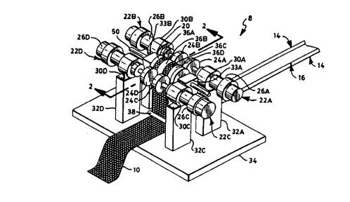
FIGURE ' snows a pictorial mew of ultrasonic bonding apparatus of the
invention.
FIGURE 2 shows a cross-section of the anvil roll, and associated rotary
ultrasonic horns.
taken at 2-2 in FIGURE 1.
FIGURE 3 shows an enlarged planar representation of a portion of the outer
surtace of
the anvil roll of FIGURE 1.
FIGURE 4 shows a cross-sectional view of a portion of the surface of the anvil
roll
including pin elements, taken at 4-4 in FIGURE 3.
FIGURE 5 shows a pictorial view of a second embodiment of apparatus of the
invention.
6
SUBSTITUTE SHEET (RULE 26)
CA 02271009 1999-OS-OS
WO 98/28123 PCT/US97/11623
FIGURE 6 shows a cross-section of the anvil roil, and associated rotary
ultrasonic horns.
taken at 6-6 in FIGURE 5.
FIGURE 7 shows a representative top view of a third embodiment of apparatus of
the
invention.
FIGURE 8 shows a cross-sectional view of the apparatus of FIGURE 7) taken at 8-
8 in
FIGURE 7.
FIGURE 9 is a bottom view, taken at 9-9 of FIGURE 8.
FIGURE 10 is a pictorial view of a fourth embodiment of ultrasonic bonding
apparatus of
the invention.
FIGURE 11 is a representative top view of the apparatus in FIGURE 10 without
the webs.
The invention is not limited in its application to the details of the
construction and the
arrangement of the components set forth in the following description or
illustrated in the
drawings. The invention is capable of other embodiments or of being practiced
or carved
out in various ways. Also, it is to be understood that the terminology and
phraseology
employed herein is for purpose of description and illustration and should not
be regarded
as limiting. Like reference numerals are used to indicate like components.
Further, the
above drawings are not drawn to scale and do not so limit the invention.
DETAILED DESCRIPTION OF THE ILLUSTRATED EM80DIMENTS
The present invention is directed toward apparatus and methods for fabricating
a web by
utilizing ultrasonic bonding. An exemplary method ultrasonically bonds the
full common
width of first and second webs using a single anvil roll and multiple rotary
ultrasonic horns.
FIGURES 1 and 2 illustrate a first an embodiment of ultrasonic bonding
apparatus 8 for
fabricating composite web 10. Turning roll 12 turns webs 14 and 16 toward
anvil roll 20.
First web 14 and second web 16 are in surface-to-surface relationship with
each other,
both at fuming roll 12 and at anvil roil 20. First and second webs 14, 16 are
drawn about
fuming roll 12 and anvil roll 20 by a pair of nip rolls 18. See FIGURE 2.
SUBSTITUTE SHEET (RULE 26)
CA 02271009 1999-OS-OS
WO 98I28123 PCT/US97/21623
Ultrasonic energy application devices 22A, 22B, 22C, 22D are positioned at
first and
second locations angularly spaced about the axis of anvil roll 20. Ultrasonic
energy
application devices 22A-22D include respective rotary ultrasonic horns 24A,
24B, 24C,
24D and ultrasonic conduit units 26A, 26B, 26C, 26D. Respective mounting
brackets
30A, 30B, 30C, 30D secure ultrasonic energy application devices 22A, 22B, 22C,
22D to
supports 32A, 32B (not shown), 32C) 32D. Supports 32A-32D are secured to base
plate
34. Mounting brackets 30A-30D bracket and secure ultrasonic energy application
devices
22A-22D to first) second, third, and fourth supports 32A-32D. Anvil roll
supports 33A, 33B
support anvil roll 20 between the respective ultrasonic energy application
devices.
First and second ultrasonic energy application devices 22A) 22B, in
combination with anvil
roil 20) apply ultrasonic energy to first and second webs 14, 16 at first and
second
locations) corresponding to a first common circumferential location on anvil
roll 20. The
ultrasonic energy applied forms bonds in respective first and third segments
36A, 36C of
first and second we'~s 14, 16. For purposes of illustration, the bonded first
and second
segments 36A) 36C are shown having a defined pattern in FIGURE 1. Second and
fourth
unbonded segments 368) 36D have not, to that point) been worked by ultrasonic
energy.
Thus) in the scenario just described) no bonds have yet been formed by
apparatus 8 in
the second and fourth segments.
Anvil roll 20 rotates at a surface speed corresponding with the speed of
advance of the
webs) namely the speed at whic;~ webs 14, 16 are drawn by nip rolls 18. Webs
14, 16
thus maintain a constant and static registration with the outer surface of
anvil roll 20 as
the webs advance about the circumference of the rotating anvil roll 20. Thus,
webs 14, 16
advance together with the outer circumferential surface of anvil roll 20. As
webs 14. 16
advance from the first and second bonding locations, anvil roll 20 carcies
webs 14) 16
toward third and fourth ultrasonic energy application devices 22C. 22D. Third
and fourth
ultrasonic energy application devices 22C. 22D. in combination with anvil roll
20) apply
ultrasonic energy to webs 14, 16 at third and fourth locations corresponding
to a second
common circumferential location on anvil roll 20. The ultrasonic energy
applied forms
bands in respective second and fourth segments 36B, 36D of first and second
webs 14,
16 to thereby form composite web 10. Where, as shown in FIGURE 1, the first)
second,
third, and fourth segments abut each other, webs 14. 16 are thus bonded to
each other
over the full common width of the two webs between the first and fourth
segments,
8
SUBSTITUTE SHEET (RULE 26)
CA 02271009 1999-OS-OS
WO 98I28123 PCTlUS97/21623
whereby full common width bonding is achieved. Additional bonding outwardly of
the
Gammon width, such as outwardly of web 16, may be obtained if desired.
Composite web 10 then advances about second turning roll 38 and downstream for
further processing or usage as a finished product.
The cross-sectional view of Fig. 2 shows the orientation of ultrasonic horns
24B, 24D with
respect to the circumference of anvil roll 20. For clarity of illustration,
certain elements,
such as supports 32A-32D) are not illustrated in the view of FIGURE 2. Arrows
40) 42
indicate the direction of movement of webs 14, 16 through apparatus 8. Arrows
44, 46,
48 indicate the directions of rotation of anvil roll 20 and rotary ultrasonic
horns 24B, 24D,
respectively.
First web 14 may be any of a wide variety of web materials, such as polyolefin
films.
porous foams. reticulated foams) apertured plastic films, or one or more
layers made with
natural fibers. A typical first web 14 may be a thin plastic film or other
flexible liquid-
impermeabie material. For example, first web 14 can be a polyethylene film
having a
thickness of from about 0.012 millimeter to about 0.051 millimeter.
When it is desirable that web 14 have a more cloth-like feeling, the web may
comprise a
polyethylene film laminated to a nonwoven web, such as a spunbonded web of
polyolefin
fibers. Thus. web 14 may comprise a polyethylene film having a thickness of
about 0.015
millimeter having thermally or otherwise laminated thereto a spunbonded web of
polyolet;n
fibers having a thickness from 1.5 to 2.5 denier per filament, which nonwoven
web has a
basis weight of about 24 grams per square meter.
Various woven and nonwoven fabrics can be used for web 1 a. For example. web
14 may
be composed of a meltblown or spunbonded web of polyolefln fibers. Web 14 may
also
comprise a carded andlor bonded web composed of natural and/or synthetic
fibers.
Further, web 14 can be formed of a woven or nonwoven fibrous web which has
been
constructed or treated, in whole or in part, to impart a desired level of
liquid impermeability
to selected regions of the web.
Web 14 may be composed of a substantially hydrophobic material wherein the
hydrophobic material is treated with a surfactant or otherwise processed to
impart a
desired level of wetability and hydrophilicity. Still further, first web 14
may optionally be
9
SUBSTITUTE SHEET (RULE 26)
CA 02271009 1999-OS-OS
WO 98I28123 PCT/US97/Z1623
composed of a micro-porous material which permits vapors to escape through the
web
while preventing liquid from passing through the web.
Web 14 can also comprise wood or cotton fibers. Other materials are synthetic
fibers,
such as polyester or polypropylene fibers, or a combination of natural and
synthetic fibers.
Web 14 can comprise a single layer, or may comprise a multiplicity of
components) layers,
or partial layers, which correspond to any of the materials disclosed herein,
as well as
others known in the art.
In a particular embodiment of the present invention, web 14 may comprise a
spunbonded
polypropylene fabric composed of about 2.8-3.2 denier fibers formed into a web
having a
basis weight of about 22 grams pet square meter and a density of about 0.06
grams per
cubic centimeter. A preferred such fabric may be treated with about 0.3 weight
percent of
a surfactant.
Web 16 can be made from any of the materials disclosed for web 14. Further)
web 16
can be made from other materials, such as elastomers, not specifically
disclosed for web
14.
In the embodiment shown in FIGURE 1, the width of web 16 is less than the
width of web
14. A turning roll or other apparatus (not shown) brings web 16 into surface-
to-surface
relationship with first web 14.
Anvil roll 20 is supported by first and second anvil supports 33A) 33B and
shaft 50. Anvil
supports 33A) 33B support anvil roll 20 from base plate 34. Shaft 50 generally
is metal,
such as steel, or other material having suitable structural properties.
FIGURE 3 shows a planar representation of a portion of the outer surface of
exemplary
anvil roil 20. The outer surface of the roll includes a base surface portion
52) and multiple
pin elements 54 extending upwardly from base surface porticn 52. Pin elements
54 are
arranged in an exemplary pattern of rows "R1" of raised pin elements 54
extending along
the length of anvil roll 20 and corresponding rows "R2" extending across the
width of anvil
roll 20 at an angle "A" of about 75 degrees with respect to rows "R1." The
centers of
individual raised pin elements in a given row "R1 "are spaced from each other
by a
distance "C," measured at the reverse angle as shown, of about 0.170 inch. As
illustrated
SUBSTITUTE SHEET (RULE 26)
CA 02271009 1999-OS-OS
WO 98!Z8123 PCT/US97/21623
in FIGURE 3, pins in adjacent rows can be offset from each other a distance
"D" of about
0.Q87 inch. In a preferred embodiment) the repeat pattern "P" for the center
of a row of
raised pin elements 54 is about 0.37 inch. The related dimension "PR" is 0.16
inch. As
illustrated, pin elements 54 provide a uniform pattern of localized discrete
bonding loci,
for bonding first and second webs 14, 16 to each other.
FIGURE 4 shows a cross-sectional view of two of pin elements 54. !n the
embodiment
shown, pin elements 54 extend upwardly from base surface 52 of anvil roll 20
to an
elevation "E" of about 0.07 inch. The substantially circular top surface 56 of
each pin
element 54 has a diameter "X" of about 0.04 inch. The outer generally conical
surTace of
a given pin element 54 extends upwardly from base surface 52 toward top
surface 56 at
an inward angle a of about 15 degrees with respect to vertical axis "V".
While an exemplary pattern of raised discreet and localized pin elements 54
has been
illustrated and described) within the outline of the area of the outer surface
of roll 20 to be
used in forming bonds. there is no criticality to the particular bond pattern
or the structure
of any raised pins or other elements. Thus, top surfaces 56 need not be
circular. The
spatial arrangement of pin elements 54 with respect to each other is not
critical. Indeed) a
pattern of raised lines may be used. Such lines may be, for example,
continuous or
discontinuous, crossing or non-cr ossing, straight or not straight.
Turning roil 12 may be driven, or may be an idler roll suctz that there is no
direc: onve of
the roll. Preferably, turning roll 12 moves substantially at the same speed as
first and
second webs 14, 16. Second fuming roll 38 can be similar or identical to
fuming roll 12.
Ultrasonic energy application devices 22A-22D include respective rotary
ultrasonic horns
24A. 24B. 24C. 24D and ultrasonic conduit urnts 26A. 26B. 26C. 260. Ulirasonrc
energy
application devices 22A-22D can compose, for example. devices set forth in
U.S. Patent
5.096.532 issued March 17) 1992 to Neuwirth et al) U.S. Patent 5,087,320
issued
February 11. 1992 to Neuwirth, or U.S. Patent 5.110,403 to Ehfert issued May
5, 1992, all
of which patents are hereby incorporated by reference in their entireties. In
some
embodiments, each ultrasonic energy application device 22A-22D applies
mechanical
pressure to webs 14, 16 across the width of the respective rotary ultrasonic
horn 24 at a
magnitude representing up to about 50 pounds per linear inch across the width
of the
energy-applying surface of the respective rotary ultrasonic horn. The width of
each
t1
SUBSTITUTE SHEET (RULE 26)
CA 02271009 1999-OS-OS
WO 98/281Z3 PCT/US97/21623
respective rotary ultrasonic horn 24 generally is about 3 inches or less.
Greater widths
are useful therein to the extent suitable rotary ultrasonic horns are
available. In one
embodiment, each ultrasonic horn 22 can apply about 800 Watts of energy.
The mechanical pressure applied to webs 14, 16, the speed of the webs, the
power
supplied by ultrasonic horn 24, and the material of the webs being worked have
an effect
on the final product that is made. For example, increasing the speed of travel
of the webs
requires increased mechanical pressure and/or increased ultrasonic energy to
perform
banding in the shorter time period the webs are being worked by ultrasonic
horn 24.
Therefore, the values for the mechanical pressure applied to the webs and the
ultrasonic
energy applied by ultrasonic horn 24 can vary beyond the ranges or values
disclosed
earlier, depending on the material being worked and the speed of the webs.
Mounting brackets 30A-30D can be pillow blocks or other well known support
elements
securing respective ultrasonic energy application devices 22A-22D to supports
32A-32D.
Base plate 34 provides a mounting base for supports 32A-32D. Base plate 34
generally
campuses a metal, such as steel. In other embodiments, base plate 34 can be
replaced
by the cement floor of a factory or other suitable support. Thus) base plate
34 need not
be present per se in all embodiments.
First through fourth segments 36A-36D of webs 14. 16 represent respective
portions of
the ~nndths of the first and second webs 14. 16. Each segment 36A-36D
comprises pan of
the mdth of at least one of the respective webs and extends along
substantially the entire
length of the respective web. Thus the first through fourth segments 36A-36D
are
substantially parallel to one another. Second segment 368 is adjacent first
segment 36A
and third segment 36C. Third segment 36C is adjacent fourth segment 36D and,
of
course) second segment 36B. Segments 36A- 36D may have the same width.
However.
ultrasonic horns having different widths with respect to each other can be
utilized with the
invention. Thus, the segments need not have the same width. Further, where the
outermost horns 24B, 24C, which operate on segments 36A, 36D respectively,
overlie any
portion of web 14 which extends outwardly of web 16, the first and fourth
segments of
web 14 may be wider than the respective first and fourth segments of web 16.
Drive apparatus (not shown) drives shaft 50 and rotates anvil roll 20 about
the shaft in the
direction of arrow 44 (FIGURE 2) at a speed generally corresponding to the
speed at
t2
SUBSTITUTE SHEET (RULE 26)
CA 02271009 1999-OS-OS
WO 98/28123 PCT/US97/21623
which webs 14) 16 advance through the bonding apparatus 8. Rotary ultrasonic
hums
24A-24D rotate cooperatively against the outer surface of anvil roll 20) as
shown by arrow
46 in FIGURE 2. Rotary ultrasonic horns 24C, 24D similarly rotate in the
direction shown
by arrow 48.
In operation, first and second webs 14, 16 advance about turning roll 12
thence onward to
anvil roll 20. Anvil roll 20 has a pattern such as the pattern illustrated in
FIGURE 3. First
and second rotary ultrasonic horns 24A) 24B and raised pin elements 54, in
combination,
form nips between anvil roll 20 and the respective horns. At the nips, first
and second
rotary ultrasonic horns 24A, 24B ultrasonically bond first and third segments
36A) 36C of
first and second webs 14, 16 to each other.
As webs 14, 16 advance past horns 24A) 24B, the ultrasonic bonding
continuously
produces a pattern) which may be spatially continuous (a line pattern) or
discontinuous
(dot pattern from pin elements 54), or a combination of continuous and
discontinuous.
The pattern may further be regular or irregular.
First and second rotary ultrasonic horns 24A) 24B are spaced from each other
and have
respective f rst and second axes of rotation. The second axis of rotation is
substantially
aligned with the first axis of rotation. The first axis of rotation is
substantially
perpendicular to the direction of travel of first and second webs 14, 16.
First and second
webs 14, 16, bonded at segments 36A, 36C are then advanced, along with
correspcnding
rotational advance of the outer surface of anvil roll 20. about 180 degrees)
to the opposite
side of the anvil roll 20 to positions of third and fourth rotary ultrasonic
horns 24C, 24D.
See FIGURE 2.
Third and fourth rotary ultrasonic horns 24C. 24D. m combination with pin
elements 54 of
anvil roll 20, form nips. At the nips, third and fourth rotary ultrasonic
horns 24C. 24D
ultrasonically bond second and fourth segments 36B. 360 of first and second
webs 14, 16
to each other. Third and fourth rotary ultrasonic horns 24C, 24D are spaced
from each
other at third and fourth locations and have respective third and fourth axes
of rotation.
The third axis of rotation is substantially aligned with the fourth axis of
rotation. The third
axis of rotation is generally substantially perpendicular to the direction of
travel of first and
second webs 14, 16. Third and fourth rotary ultrasonic horns 24C, 24D can
continuously
produce a pattern of bonds bonding the fsrst and second webs to each other.
The pattern
13
SUBSTITUTE SHEET (RULE 26)
CA 02271009 1999-OS-OS
WO 98/28123 PCT/US97/21623
may be spatially continuous or discontinuous) and otherwise as described with
respect to
the first and second horns.
Composite web 10 and, of course, first and second webs 14, 16, can be drawn
through
ultrasonic bending apparatus 8 at a speed of at least about 600 feet/minute,
preferably at
least about 1000 feetlminute. Anvil roll 20 is preferably driven to promote
common
registration of webs 14, 16 to both sets of horns 24A, 24B and 24C) 24D, as
well as to
generally promote movement of webs 14, 16 therethrough. Turning roll 38 turns
composite web 10 and the web advances beyond ultrasonic bonding apparatus 8
for
further processing or storage on a wind- up roll (not shown). Formation of
composite web
10 is accompanied by ultrasonic bonding of preferably the first through fourth
segments
36A-360 on each of webs 14, 16. In some embodiments, less than all segments
may be
bonded. However, bonding at all segments is preferred.
By utilizing a single anvil roll 20, fuming at a surface speed corresponding
to the speed of
advance of webs 14, 16 through apparatus 8, registration established between
webs 14)
16 and anvil roll 20 at horns 24A) 24B is maintained at feast until webs 14,
16 have
advanced past horns 24C) 24D. This better control and registration is
especially
noticeable when compared to multiple bonders using multiple anvils to create a
single
bond pattern. Thus, the registration of bond points of first and second webs
14, 16) as
created by prn elements 54, is more precise since all of the ultrasonic
bonding occurs cn
single anml roll 20 while webs 14, 16 remain stationary mth respect to the
outer surface f
the anvil roll.
FULL WIDTH BONDING
In some embodiments, the ennre full widths of webs 14. 16 can be bonded
together at
selected locations, as shown in FIGURE 1, to form composite web 10. As used
herein)
"full width" of the webs means at least 80% and preferably up to 100% of the
overall width
of the narrower of webs 14) 16. Full width bonding preferably bonds the outer
edge of a
narrower web to the facing surface of the corresponding wider web. "Full width
bonding"
expresses overall width of the area generally bonded) irrespective of the bond
pattern
used. Full width bonding does comprehend the pattern of discrete points
illustrated in
FIGURE 3. Thus, full width bonding can be accomplished by ultrasonic bonding
of a
pattern across and along the width of the web. For example. the pattern of
bonds
14
SUBSTITUTE SHEET (RULE 26)
CA 02271009 1999-OS-OS
WO 98/28I23 PCT/US97/21623
suggested by FIGURES 3 and 4 can be used for full width bonding to the extent
the
pattern of dot bonds extends the "full width" of the respective web.
FIGURE 1 shows an example of full width bonding at composite web 10. First,
second)
third and fourth rotary ultrasonic horns 22A-22D are configured and spaced
across the
widths of webs 14, 16 at the respective first through fourth locations in a
staggered
arrangement such that no substantial areas of webs 14, 16 receive bonding
energy from
two or more of the ultrasonic horns. Thus, first through fourth ultrasonic
horns are
staggered or spaced apart along the longitudinal orientation of webs 14, 16,
so that
substantially no surface contacted by one of the rotary ultrasonic horns is
contacted by
another ultrasonic horn. As used herein, "staggered" means being spaced apart
in the
direction of movement of the webs being worked as well as spaced transverse to
the
length of the web being worked, such that a surface of a web already worked by
an
upstream rotary ultrasonic horn is not contacted by, or receives only minimal
contact from.
a downstream rotary ultrasonic horn. However, close abutment of the areas
worked by
the upstream and downstream horns is preferred, and some inadvertent overlap
may thus
occur. In this manner, the entire transverse common width of the first and
second webs
14, 16, and optionally the entire width of web 14, can be bonded.
Where the full widths of two webs are bonded to each other as illustrated in
FIGURE 1,
construction adhesives normally used to bond such webs can be eliminated, with
corresponding cost savings.
Refemng again to FIGURE 1, the bonding referred to has been described in terms
of
bonding webs 14, 16 to each other (interweb bonding). In addition, where one
or both of
webs 14. 16 are comprised of non-sheet elements (e.g. fibers ), the bonding
includes
consolidation to each other of adjacent fibers within each web (intrawed
bonding).
Especially where one or both webs comprise non-sheet elements, bonding
typically
includes both interweb and intraweb bonding. Any bonding of web 14 outside the
width of
web 16 is) of course, intraweb bonding.
MULTIPLE-STAGE COMBINING
FIGURE 5 illustrates another family of embodiments of apparatus 108 of the
invention
wherein the prefix "1" indicates the instant embodiment. Second and third
digits are used
~5
SUBSTITUTE SHEET (RULE 26)
CA 02271009 1999-OS-OS
WO 98I28123 PGT/US97/21623
in common with the earlier embodiment. Apparatus 108 for fabricating composite
web
110 includes turning roll 109. Turning roll 109 disposes first web 114 and
second web
116 into surface-to-surface relationship with each other. Webs 114, 116 are
drawn over
anvil roll 20, about second turning roll 112 and anvil roll 120 as in the
first embodiment.
Ultrasonic energy application devices 122A, 122B, 122C and 122D are positioned
at first
and second angular orientations about the circumference of anvil roll 120.
Ultrasonic
energy application devices 122A-122D include respective rotary ultrasonic
horns 124A,
124B, 124C, 124D and ultrasonic conduit units 126A, 1268, 126C, 126D.
Respective
mounting brackets 130A, 130B. 130C, 130D secure respective ultrasonic energy
application devices 122A-122D to supports 132A) 132B (not shown), 132C, 132D.
Supports 132A-132D are secured to base plate 134. Mounting brackets 130A-130D
bracket and secure ultrasonic energy application devices 122A-122D to
respective
supports 132A-132D. Anvil roll supports 133A. 133B support anvil roll 120
between the
respective ultrasonic energy application devices.
Additional third web 118 and fourth web 119 are disposed in surface-to-
surface
relationship with first and second webs 114. 116 by respective fixedly mounted
turning
rolls 158. 159 disposed downstream of ultrasonic energy application devices
122A. 122B.
Third web 118 and fourth web 119 travel toward anvil roll 120 in the
respective directions
shown by arrows 162. 164. Third and fourth webs 118, 119 thus come into facing
relationship with webs 114, 116 after first and second ultrasonic energy
application
devices 122A, 1228) in combination with anvil roll 120, apply ultrasonic
energy to first and
second webs 114, 116 at the first and second locations.
The ultrasonic energy applied preferably forms ultrasonic bonds between webs
114, 116
in segments defined by respective widths of webs 114, 116. Third web 118 is
drawn
about turning roll 158 and into surface-to-surface relationship with first and
second webs
114, 116. At a further downstream location about the circumference of anvil
roll 120,
fourth web 119 is drawn about turning roll 159 and into surface- to-surface
relationship
with third web 118 and) if web 119 is wider than web 118, then also
potentially into contact
with web 114, optionally web 116. Third and fourth webs 118, 119 generally are
drawn
across anvil roll 120 at substantially the same speed as first and second webs
114, 116.
Any portions of first and second webs 114, 116 not covered by third web 118
can thus be
in surface-to-surface relationship with fourth web 119. The first through
fourth webs thus
16
SUBSTITUTE SHEET (RULE 26)
CA 02271009 1999-OS-OS
WO 98I28123 PCT/US97/Z1623
advance together toward third and fourth ultrasonic energy application devices
122C,
122D. Third and fourth ultrasonic energy applicakion devices 122C, 122D apply
ultrasonic
energy at third and fourth locations to respective segments of the first
through fourth webs
to form composite web 110. Composite web 110 then advances about turning roll
138
and downstream, for further processing, or far usage as a finished product.
The cross-sectional view of FIGURE 6 shows the arrangement between anvil roll
120 and
second and fourth rotary ultrasonic horns 124B, 124D. For purposes of
illustration,
certain elements, such as supports 132A-132D, are not illustrated in the view
of FIGURE
6. Arrows 140, 142 indicate the direction of movement of the webs through
apparatus
108. Arrows 144. 146, 148 indicate the direction of rotation of anvil roll 120
and second
and fourth rotary ultrasonic horns 124B, 124D, respectively.
First web 114) second web 116, third web 118, and fourth web 119 can all
comprise the
7 5 same or similar materials, or other unrelated materials as disclosed
earlier with respect to
first and second webs 14, 16. Thus same or ail of the first through fourth
webs can be
made of different materials.
Anvil roll 120, first and second anvil supports 133A) 133B, base plate 134,
supports 132A-
132D, mounting brackets 130A-130D and the like generally comprise metal, such
as steel.
Anvil roll 120 can have thereon the pattern of pin elements shown in FIGURES 3-
-t, or any
other smtable pattern, to bond the webs to each other. The embodiment of
FIGURES 5
and 6 preferably has a drive apparatus as disclosed with respect to the
embodiment of
FIGURES t and 2.
In operation, anvil roll 120 rotates on shaft 150, fuming with the advance of
first and
second we0s 114, 116 about tummg roll 112. As in FIG. 1, first and second
ultrasonic
horns 124A, 124B ultrasonically bond respective first and second segments of
the first
and second webs to each other. Turning roll 158 places third web 118 in
surface-to-
surface relationship with first and second webs 114, 116 on anvil roll 120.
Turning roll 158
can be disposed about 45 degrees about the axis of rotation of anvil roll 120
with respect
to the nips formed between first and second rotary ultrasonic horns 124A, 124B
and the
anvil roll.
17
SUBSTfTUTE SHEET (RULE 26)
CA 02271009 1999-OS-OS
WO 98I28123 PCT/US97/21623
About another 90 degrees downstream on anvil roll 120, but before the third
and fourth
rotary ultrasonic horns, turning roll 159 places fourth web 119 in surface-to-
surface
relationship with third web 118 and potentially in surface-to- surface
relationship with
portions of first and second webs 114, 116 not covered by the third web. Third
and fourth
rotary ultrasonic horns 124C, 124D) in combination with anvil roll 120, form
nips. At the
nips, third and fourth rotary ultrasonic horns 124C) 124D ultrasonically bond
segments of
the third and fourth webs to each other and to the first and second webs, to
finish forming
composite web 110. At least one of the segments bonded at downstream horns
124C,
124D can overlap with at least one of the segments previously bonded by
upstream rotary
ultrasonic horns 124A, 124B. As used herein) "overlapping" means that a
portion across
the width of the segment bonded by third and fourth rotary ultrasonic horns
124C) 124D,
has previously been bonded by one of first and second rotary ultrasonic horns
124A,
124B. Thus at least part of a previously bonded segment can be, but need not
be)
"repeat bonded" in forming composite web 110. Turning roll 138 turns composite
web 110
and the web advances for further processing, or storage on a wind-up roll (not
shown) or
the like.
TABLE ARRANGEMENT
FIGURES 7-9 illustrate another family of embodiments of apparatus 8 of the
invention
wherein the prefix "2" indicates this family of embodiments. Second and third
digits are
used in common with the earlier embodiments. FIGURE 7 shows, in plan view,
apparatus
208 simitar to apparatus 8 shown in FIGURE 1. For purpose of illustration,
FIGURE 7
does not show any webs, only the apparatus. The arrangement of ultrasonic
energy
application devices 222A. 222B, 222C) 222D with respect to anvil roll 220 is
generally the
same as the arrangement in the embodiment of FIGURE 1. The ultrasonic energy
application devices include respective rotary ultrasonic horns 224A-224D and
respective
ultrasonic conduit units 226A-226D. Mounting brackets 230A-230D mount
respective
ultrasonic energy application devices 222A-222D onto supports 232A. 2328 (not
shown))
232C, 232D (not shown). Supports 232A-232D (See FIGURE 8) are the same as the
supports shown in FIGURE 1. Anvil roll supports 233A) 233B at opposing ends of
anvil
roll 220 support the anvil roll on shaft 250. Supports 232A-232D and 233A.
233B
generally are fixed to base plate 234.
18
SUBSTITUTE SHEET (RULE 26)
CA 02271009 1999-OS-OS
WO 98/Z8123 PCT/US97/21623
As shown in FIGURE 9, first and second apertures 275) 276 are generally
configured as
slots which extend substantially the entire width of anvil roll 220. Further,
the slats of
apertures 275, 276 shown in FIGURE 9 are generally parallel to (i) the portion
of the outer
surface of turning roll 212 which is closest to turning roll 238 and (ii) the
portion of the
outer surface of anvil roll 210 which is closest to rotary ultrasonic horns
224A) 224B, and
the above outer portions (i) and (ii) in combination, define a plane which
passes through
aperture 275, preferably centered on aperture 275 as shown. A similar
arrangement
exists between the outer surface of anvil roll 220 adjacent ultrasonic horns
224C) 224D,
and turning roil 238.
As shown in the cross-sectional view of FIGURE 8) first web 214 and second web
216 are
drawn into surface-to-surface relationship with each other at turning roll
209. Thus, in this
embodiment, base plate 234 forms the top of table unit 274. Support legs 271
A. 2718
271 C) 271 D support base plate 234. In combination, support legs 271 A-271 D
and base
plate 234 form table unit 274. Thus, as shown in FIGURE 8, first and second
webs 214,
216 are drawn along a path below base plate 234 around tummg roll 212 and
toward anvil
roll 220. The respective webs pass through aperture 275 toward anvil roll 220.
As
described earlier, first and second ultrasonic energy application devices
222A. 2228, in
combination with anvil roll 220, apply ultrasonic energy to bond e.g. first
and third
segments of first and second webs 214, 216. Third and fourth ultrasonic energy
application devices 222C. 222D ultrasonically bond e.g. second and fourth
segments of
the weds. After ultrasonic bonding is completed, composite web 210 passes
through
second aperture 276, thence to turning roll 238. Turning roll 238 turns
composite web
210 out the opposing side of table unit 274. Drawing apparatus (not shown)
draws
composite web 210 downstream for further processing or storage on a wind-up
roll or the
like.
MULTIPLE EFFECT 80NDING OF WEBS
FIGURES 10 and 11 illustrate yet another family of embodiments of apparatus 8
of the
invention wherein the prefix "3" indicates this family of embodiments. Second
and third
digits are used in common with the earlier embodiments. FIGURE 10 shows
ultrasonic
bonding apparatus 308 for fabricating composite web 310 similar to apparatus 8
shown in
FIGURE 1 except only two rotary ultrasonic horns 324A) 324B are present.
Ultrasonic
horns 324A. 3248 are substantially in alignment with each other across first
and second
19
SUBSTITUTE SHEET (RULE 26)
CA 02271009 1999-OS-OS
WO 98I28123 PCT/US97I21623
webs 314, 316. The top view of FIGURE 11 shows ultrasonic bonding apparatus
308
having first and second rotary ultrasonic horns 324A, 324B aligned across the
width of
anvil roll 320. No webs are shown in FIGURE 11.
Returning now to FIGURE 10, webs 314 and 316 are disposed in surface-to-
surface
relationship with each other. Webs 14, 16 are drawn about a turning roll (not
shown)
toward the anvil roll.
Ultrasonic bonding apparatus 308 includes ultrasonic energy application
devices 322A,
322B spaced about the circumference of anvil roll 320 (e.g. 180 degrees
apart).
Ultrasonic energy application devices 322A. 322B include respective rotary
ultrasonic
horns 324A, 3248 and ultrasonic conduit units 326A. 326B. Respective mounting
brackets 330A, 330B secure ultrasonic energy application devices 322A, 322B to
supports
332A. 332B. Supports 332A. 332B are secured to base plate 334. Mounting
brackets
330A. 330B secure ultrasonic energy application devices 322A. 322B to first
and second
supports 332A. 332B. Supports 333A, 333B support anvil roll 320, positioned
between
the respective ultrasonic energy application devices.
First and second ultrasonic energy application devices 322A, 3228, in
combination with
anvil roll 320, apply ultrasonic energy to first and second webs 314, 316 at
first and
second locations spaced about the circumference of the anvil roll. The
ultrasonic energy
applied has a first effect at first bond loci in segment 336 of first and
second webs 314.
316. This first effect can include bonding of the first and second webs 314.
316 to each
other (interweb bonding) as well as bonding together fibers or the like within
a given one
of the webs (intraweb bonding). Rotation of anvil roll 320 carries webs 314,
316 toward
second ultrasonic energy application device 322B. Second ultrasonic horn 324B
applies
ultrasonic energy to segment 336 in registration, and at the same bond loci,
as the energy
applied by first ultrasonic horn 324A. This second application of energy to
the same loci
has a second effect on segment 336. The second effect can include
substantially bonding
the first and second webs to each other at segment 336 to form composite web
310
(interweb bonding), as well as intraweb bonding. Composite web 310 then
advances
about turning roil 338 and downstream for further processing, or usage as a
finished
product.
SUBSTITUTE SHEET (RULE 26)
CA 02271009 1999-OS-OS
WO 98I28123 PCT/US97/21623
The above method of multiple effect bonding can be applied to consolidating a
batt of
ultrasonically fusible fibers to make a consolidated web. Refer-ing generally
to
FIGURES 10 and 11, but in application to a loose, generally unconsolidated
batt or mat of
fibers, such method includes feeding the batt or mat of fibers in a feed
direction into
operative engagement with anvil roll 320. The batt or mat is, of course,
provided with
suitable preliminary consolidation so that the batt or mat can be fed over
anvil roll 320.
First rotary ultrasonic horn 324A applies ultrasonic energy to superposed ones
of the
fibers at the nip formed between ultrasonic horn 324A and anvil roll 320.
Subsequently,
second rotary ultrasonic horn 324B applies ultrasonic energy to the superposed
fibers in
registry with the first application of ultrasonic energy at horn 324A.
Thus) second ultrasonic horn 324B applies energy to locations/spots, etc. on
the batt or
mat which have already received a first application of ultrasonic energy by
the first ham
324A. Thus. the second horn applies a second treatment of energy to locations
on the
batt which earlier received energy from horn 324A. The net result of the
second
applications of energy to locations on the batt which earlier received first
applications is
that enhanced consolidation of the batt can be achieved, or a given level of
consolidation
can be achieved at greater operating speeds, namely greater web speeds of the
web
traversing anvil roll 320.
Accordingly, the consolidation operation can be performed in a single effect
bonding as in
e.g. FIGURES 1-2) albeit at sfower speeds of advance of the batt or mat or
web.
FIGURE 11 shows the alignment of rotary ultrasonic horns 324A. 324B about the
circumference of anvil 320. Rotary ultrasonic horns 324A. 324B are arranged to
bond
respective webs 314, 316 across a common width of segment 336. This multiple
effect
bonding of a given width of webs 314, 316 can increase the overall bond
strength of
composite web 310 as well as provide for enhanced process operating speed.
Further, third and fourth ultrasonic horns (not shown) can be arranged in
substantial
upstream-downstream alignment with each other on anvil roll 320, and beside
the
respective first and second ultrasonic horns. Thus) as first and second webs
314, 316 are
bonded at a common segment by first and second ultrasonic horns 324A, 324B,
other
ultrasonic horns (not shown) can similarly bond second, third, fourth) etc.
segments of the
webs. !n such scenario, each respective segment of the webs can receive
multiple
21
SUBSTITUTE SHEET (RULE 26)
CA 02271009 1999-OS-OS
WO 98I28123 PCT/US97/21623
applications (at least two) of ultrasonic energy) preferably while maintaining
registry on a
single anvil, with a short interval between the bondings.
Typically, the interval is sufficiently short that at least some of the
thermal energy created
at the first application of ultrasonic energy remains present undissipated in
the webs)
when the subsequent application of ultrasonic energy is applied. Thus, the
webs) are
e.g. still warm from an earlier application of energy when a subsequent
application of
energy is applied, whereby the combined applications of energy work together
in creating
the final bonding. Thus, the first application of energy can make a first
change in the
materials due to the heat, pressure and energy involved. The second
application of
energy at the same locations in the webs can further change the materials of
webs 314,
316.
Multiple bonding of the webs can allow the equipment to operate at faster
speeds than
would be possible with a single application of energy. As contemplated herein,
the webs
may not be firmly bonded to each other at the first ultrasonic hom. Rather,
bonding
develops sequentially as the respective home apply energy multiple times to
the
respective bond loci. Thus) the webs) can advance at speeds faster than those
previously
known for ultrasonic bonding. For example, ultrasonic banding apparatus 308
can
operate at web speeds greater than 600 feet/minute, greater than 1000 feet per
minute,
and even greater than 1300 feet per minute, because multiple banding hits on a
gmen
bond locus can. in cambination, provide sufficient effective contact time for
ultrasornc
bonding when operating at such a high speed and with subsequent bonding hits
occurring
before dissipation of latent energy applied in an earlier hit.
A critical characteristic of this embodiment is multiple applications of
ultrasonic energy to
any given bond locus on the web. Thus, the second hit of bonding energy is
applied to
bond loci that have already received a first application of ultrasonic energy.
To that end.
maintaining registration of the bond loci at the first application of energy
with the bond loci
at the second application of energy, such that the first and second bond loci
are at
identical locations on the web, is an important feature of this embodiment.
Accordingly, at
least some of the first and second bond loci will overlap each other.
By providing a sufficient number of additional ultrasonic horns, spaced across
the widths
of the webs, multiple ultrasonic bonding can occur across the full widths of
webs 314, 316.
22
SUBSTITUTE SHEET (RULE 26)
CA 02271009 1999-OS-OS
WO 98/28123 iPCT/US97/216?,3
In addition) speeds can be further increased by providing additional
ultrasonic horns,
aligned with each other and with the respective segments, and thus additional
applications
of energy within the critical timing wherein subsequent applications build on
energy
applied by upstream horns.
OTHER VARIATIONS
In some embodiments, additional ultrasonic energy application devices (not
shown) may
be disposed and arranged about anvil roll 20, as necessary, to ultrasonically
bond the first
and second webs across substantially the entire width of the webs.
Additional ultrasonic energy application devices can also be utilized to
secure any number
of webs to each other. For example, while FIGURE 1 shows first and second webs
1 a, 16
being disposed in surface-to-surface relationship with each other before
ultrasonic
bonding occurs, three or more webs can be disposed in contact with each other
before
reaching anvU roil 20.
Ultrasornc bonding apparatus 208 of FIGURES 7-9 can also be arranged to band
the
center of a wide web by having the apertures in base plate 234 formed in table
top 234.
Thus ultrasonic energy application devices can be mounted such that the
mounting locus
~s within the projected width of webs 214, 216.
In some embodiments of the invention, mounting brackets 30A-30D can be formed
as
integral parts of supports 32A-32D. In some embodiments of the invention)
anvil roll
supports 33A. 338 can be integral with base plate 34 or supports 32A-32D. In
some
embodiments of the invention, base plate 34 can be replaced by earth, e.g. the
factory
floor supporting ultrasonic bonding apparatus 8.
Raised pin elements 54 can have various shapes, sizes, and spacing
arrangements. For
instance, individual raised elements 54 can have a rectangular shape, star
shape or any
other shape. The spacing between raised pin elements 54 can be varied as
desired far
the degree of securement needed for first and second webs 14, 16 to each
other. Rows
of pin elements 54 can be replaced with decorative patterns or other designs
for raised
elements at selected portions of anvil roll 20.
23
SUBSTITUTE SHEET (RULE 26)
CA 02271009 1999-OS-OS
WO 98/Z8123 PCT/US97/21623
Variations described with respect to any one embodiment of the invention can
be utilized
by any other embodiment of the invention. For example) the raised pin elements
54 or
any variation of the embodiment of FIGURE 1 can be utilized in all of the
other
embodiments as the pattern for the anvil roll.
Methods and apparatus described herein can be used to consolidate a batt of
ultrasonically fusible fibers into a web. The apparatus can be as illustrated
above. A
typical method includes feeding the batt of fibers in a feed direction into
operative
engagement with anvil roil 20. Referring generally to the apparatus
illustrated in
FIGURE 1, but wherein the apparatus is operating on a fibrous batt rather than
on two
previously consolidated webs) ultrasonic horns 24A and 24B bond superposed
ones of
fibers in first segment 36A of the batt to each other, at a first nip formed
between horn
24A and anvil roll 20, and ultrasonically bond superposed ones of fibers in
third segment
36C to each other, at a second nip formed between horn 248 and anvil roll 20.
The
second nip is disposed at the same angular orientation with respect to the
anvil roil as the
first nip. as illustrated in the drawings. The method further comprises
ultrasonically
bonding superposed ones of fibers in the second segment 368 to each other, at
a third
nip formed between horn 24D and anvil roil 20. The third nip is disposed at an
angular
orientation, displaced about the anvil roll from the first and second nips. A
fourth bonding
nip may also be used as illustrated at horn 24C.
Those skilled m the art will now see that certain modifications can be made to
the
mvennon herein disclosed with respect to the illustrated embodiments, without
departing
from the spirit of the instant invention. And while the invention has been
described above
wrath respect io the prefer-ed embodiments, it will be understood that the
invention is
adapted to numerous rearrangements. modifications, and alterations. all such
arrangements, modifications, and alterations are intended to be within the
scope of the
appended claims.
24
SUBSTITUTE SHEET (RULE 26)