Language selection

Search

Patent 2271043 Summary

Third-party information liability

Some of the information on this Web page has been provided by external sources. The Government of Canada is not responsible for the accuracy, reliability or currency of the information supplied by external sources. Users wishing to rely upon this information should consult directly with the source of the information. Content provided by external sources is not subject to official languages, privacy and accessibility requirements.

Claims and Abstract availability

Any discrepancies in the text and image of the Claims and Abstract are due to differing posting times. Text of the Claims and Abstract are posted:

  • At the time the application is open to public inspection;
  • At the time of issue of the patent (grant).
(12) Patent: (11) CA 2271043
(54) English Title: BOLT-TOGETHER HITCH FOR ARTICULATED MACHINE
(54) French Title: BARRE D'ATTACHE BOULONNEE POUR MACHINE ARTICULEE
Status: Deemed expired
Bibliographic Data
(51) International Patent Classification (IPC):
  • B62D 53/02 (2006.01)
(72) Inventors :
  • FAIRLESS, TERENCE (United Kingdom)
  • POLLOCK, ANTHONY J. (United Kingdom)
(73) Owners :
  • CATERPILLAR INC. (United States of America)
(71) Applicants :
  • CATERPILLAR INC. (United States of America)
(74) Agent: KIRBY EADES GALE BAKER
(74) Associate agent:
(45) Issued: 2006-08-01
(86) PCT Filing Date: 1998-09-28
(87) Open to Public Inspection: 1999-04-08
Examination requested: 2003-09-12
Availability of licence: N/A
(25) Language of filing: English

Patent Cooperation Treaty (PCT): Yes
(86) PCT Filing Number: PCT/US1998/020292
(87) International Publication Number: WO1999/016662
(85) National Entry: 1999-04-30

(30) Application Priority Data:
Application No. Country/Territory Date
08/941,843 United States of America 1997-10-01

Abstracts

English Abstract


A bolt-together hitch for a machine having
articulatable first and second sections, including a
generally annular yoke member of cast steel having a
cylindrical portion which is trunnion mounted by
bearings in a longitudinal bore formed by the first
section and a tube member of forged steel bolted end to
end to the yoke member, the yoke member integrally
forming brackets to provide an articulated pivot joint
with the second section.


French Abstract

L'invention concerne une barre d'attache boulonnée (16) destinée à une machine (10) dans laquelle des première et seconde parties peuvent s'articuler (12, 14). Ladite barre comprend un collier généralement annulaire (30) en acier moulé. Ce collier comporte une partie cylindrique en montage à tourillon (34) réalisé au moyen de coussinets (40, 42) dans un alésage longitudinal formé par la première partie (12) et un élément tubulaire (20) en acier forgé boulonné bout à bout sur le collier (30), auquel sont intégrées des pattes de fixation qui fournissent une articulation rotoïde pour l'attelage de la seconde partie (14).

Claims

Note: Claims are shown in the official language in which they were submitted.


-9-
Claims
1. A hitch assembly for an articulated machine, the
machine having front and rear sections, the hitch
permitting articulation of the machine sections about a
vertical axis, comprising:
a tube member comprising forged steel and having
opposing ends and an outer surface, the surface being
wear-resistant and hardened, the tube member having a
plurality of bolt holes at one of the ends and being
pivotally supported at the other end by one of the
sections;
a yoke member comprising cast steel and having
opposing ends, one of the ends having a plurality of
bolt-receiving holes which are axially alignable with
the bolt holes of the tube member, and the other of the
ends having a pair of spaced apart receptacles for
receiving pivoting means for pivoting the hitch
assembly about the vertical axis, the yoke member
further including a boss for receiving pivot actuating
means, the yoke member being removably fastenable to
the tube member; and
a plurality of fasteners receivable in the axially
alignable holes for fastening the tube and yoke members
together such that when said fasteners are removed from
the bolt-receiving holes, said tube member is axially
movable in a direction from the tube member's one end
toward the tube member's other end.


-10-
2. The hitch assembly as set forth in claim 1 wherein
the tube member further comprises an inner surface
adapted for use with a bearing for rotatably supporting
a drive shaft extending between the sections.
3. A hitch assembly for an articulated machine, the
machine having front and rear sections, the hitch
permitting articulation of the machine sections about a
vertical axis, comprising:
a tube member having opposing one and an other
ends with a flange being disposed at said one end and
an outer surface wherein said surface comprises wear-
resistant, relatively hard material; and
a yoke member having opposing ends, a passageway
extending between said opposing ends, and a pair of
spaced apart receptacles for receiving pivoting means
for pivoting the hitch assembly about the vertical
axis, said yoke member comprising material of
relatively high strength and being removably fastenable
at one end to the tube member, wherein
(i) said yoke member's one end, during fastening
of said tube member thereto, is abutted by said tube
member's flange when said tube member moves in a
direction from its other end toward its one end and
(ii) said tube member does not extend into said
passageway of said yoke member when said one end of
said yoke member is removably fastened to said tube
member.


-11-
4. The hitch assembly as set forth in claim 3 further
comprising a boss on the yoke member for receiving
pivot actuating means.
5. A hitch assembly for a machine having front and
rear sections each with ground engaging members driven
by a drive shaft wherein the hitch permits articulation
of the sections about a vertical axis, said hitch
comprising:
a tube member having one and an other end, inner
and outer surfaces, and a flange at one of the ends
having a plurality of bolt holes, the surfaces being
relatively wear-resistant and hardened wherein the
inner surface provides rotatable support for the drive
shaft and the outer surface is rotatably supported at
the other end by one of the front and rear sections;
and
a yoke member fixed to the other one of the front
and rear sections and having one and an other end
wherein said one end has a plurality of bolt holes,
said one ends of the tube member and the yoke member
being axially abuttable such that said bolt holes of
said tube member are axially alignable with said bolt
holes of said yoke member for reception of bolts in
said aligned holes to fixedly join said members,
wherein the members, when in the axially abuttable but
not fixedly joined relationship, permit each member to
be moved in a direction from its one end toward its
other end.


-12-
6. A hitch assembly for an articulated machine, the
machine having front and rear sections, the hitch
permitting articulation of the machine sections about a
vertical axis, comprising:
a tube member comprising forged steel and having
opposing ends and an outer surface, the surface being
wear-resistant and hardened, the tube member having a
plurality of fastener holes at one of the ends and
being pivotally supported at the other end by one of
the sections;
a yoke member comprising cast steel and having
opposing ends, one of the ends having a plurality of
fastener-receiving holes which are axially alignable
with the fastener holes of the tube member, and the
other of the ends having a pair of spaced apart
receptacles for receiving pivoting members that are
configured to pivot the hitch assembly about the
vertical axis, the yoke member further including a boss
for receiving a pivot actuator, the yoke member being
removably fastenable to the tube member, and
a plurality of fasteners receivable in the axially
alignable holes for fastening the tube and yoke members
together such that when the fasteners are removed from
the fastener-receiving holes, the tube member is
axially movable in a direction from the tube member's
one end toward the tube member's other end.


-13-
7. The hitch assembly as set forth in claim 6 wherein
the inner surface of the tube member is adapted for use
with a bearing.
8. The hitch assembly as set forth in claim 6 wherein
the pivot actuator is a steering cylinder.
9. The hitch assembly as set forth in claim 6 wherein
the pivoting members are bearings.
10. A hitch assembly for an articulated machine, the
machine having front and rear sections, the hitch
permitting articulation of the machine sections about a
vertical axis, comprising:
a tube member having opposing first and second
ends with a flange being disposed at the first end, the
tube member having an outer surface of a
wear-resistant, relatively hard material; and
a yoke member having opposing first and second
ends, a passageway extending between the first and
second ends, and a pair of spaced apart receptacles for
receiving pivoting members configured to pivot the
hitch assembly about the vertical axis, the yoke member
including a boss configured to receive a pivot
actuator, being formed of a material of relatively high
strength and being removably fastenable at the first
end to the tube member, wherein
(i) the first end of the yoke member, during
fastening of the tube member thereto, is abutted by the


-14-
flange of the tube member when the tube member is moved
in a direction from its second end toward its first
end, and
(ii) the tube member does not extend into the
passageway of the yoke member when the first end of the
yoke member is removably fastened to the tube member.
11. The hitch assembly as set forth in claim 10
wherein the pivot actuator is a steering cylinder.
12. The hitch assembly as set forth in claim 10
wherein the pivoting members are bearings.

Description

Note: Descriptions are shown in the official language in which they were submitted.


CA 02271043 1999-04-30
WO 99/16662 PCT/US98/20292
-1-
Description
Bolt-Toaether Hitch for Articulated Machine
Technical Field
This invention relates generally to a
coupling assembly for articulated machines and more
particularly to such a coupling assembly which is
bolted together.
Backaround Art
It is well known in the prior art to provide
coupling means, or a hitch, between two sections of a
machine to permit articulated movement about a
15 generally vertical pivot axis. However, such prior
art hitches are typically of integral construction and
are, thus, formed from only one material which may not
best meet the material requirements of all portions of
the hitches. For example, the portion of an
20 articulating hitch which houses drive shaft bearings
may experience significantly more wear that the
portion which houses articulation bearings. In US
Patent No. 3,773,129 issued to Anderson on 20 November
1973, a compact unitary coupling is described for
25 facilitating interconnection with two machine
sections. There, the unitary nature of the coupling
necessitates a single material of construction, which
material may not best meet the requirements of
hardness, durability or strength of a particular hitch
30 portion.
Where different materials of construction
are used in different hitch portions, the portions may
not be separated for repair or replacement of an
individual portion. For example, in the Caterpillar

i
CA 02271043 2003-09-12
-2-
D300E Articulated Truck the hitch is formed of two
portions, each of a different material, which are
robotically welded together. While providing
outstanding strength, an individual portion of a
unitary welded hitch is not repairable or replaceable.
The present invention is directed to
overcoming one or more of the problems set forth above.
Disclosure of the Invention
In accordance with one aspect of the present
invention there is provided a hitch assembly for an
articulated machine, the machine having front and rear
sections, the hitch permitting articulation of the
machine sections about a vertical axis, comprising: a
tube member comprising forged steel and having opposing
ends and an outer surface, the surface being wear-
resistant and hardened, the tube member having a
plurality of bolt holes at one of the ends and being
pivotally supported at the other end by one of the
sections; a yoke member comprising cast steel and
having opposing ends, one of the ends having a
plurality of bolt-receiving holes which are axially
alignable with the bolt holes of the tube member, and
the other of the ends having a pair of spaced apart
receptacles for receiving pivoting means for pivoting
the hitch assembly about the vertical axis, the yoke
member further including a boss for receiving pivot
actuating means, the yoke member being removably
fastenable to the tube member; and a plurality of
fasteners receivable in the axially alignable holes for

i
CA 02271043 2003-09-12
-3-
fastening the tube and yoke members together such that
when said fasteners are removed from the bolt-receiving
holes, said tube member is axially movable in a
direction from the tube member's one end toward the
tube member's other end.
In accordance with another aspect of the
present invention there is provided a hitch assembly
for an articulated machine, the machine having front
and rear sections, the hitch permitting articulation of
the machine sections about a vertical axis, comprising:
a tube member having opposing one and an other ends
with a flange being disposed at said one end and an
outer surface wherein said surface comprises
wear-resistant, relatively hard material; and a yoke
member having opposing ends, a passageway extending
between said opposing ends, and a pair of spaced apart
receptacles for receiving pivoting means for pivoting
the hitch assembly about the vertical axis, said yoke
member comprising material of relatively high strength
and being removably fastenable at one end to the tube
member, wherein (i) said yoke member's one end, during
fastening of said tube member thereto, is abutted by
said tube member's flange when said tube member moves
in a direction from its other end toward its one end
and (ii) said tube member does not extend into said
passageway of said yoke member when said one end of
said yoke member is removably fastened to said tube
member.

CA 02271043 2003-09-12
-4-
In accordance with yet another aspect of the
present invention there is provided a hitch assembly
for a machine having front and rear sections each with
ground engaging members driven by a drive shaft wherein
the hitch permits articulation of the sections about a
vertical axis, said hitch comprising: a tube member
having one and an other end, inner and outer surfaces,
and a flange at one of the ends having a plurality of
bolt holes, the surfaces being relatively
wear-resistant and hardened wherein the inner surface
provides rotatable support for the drive shaft and the
outer surface is rotatably supported at the other end
by one of the front and rear sections; and a yoke
member fixed to the other one of the front and rear
sections and having one and an other end wherein said
one end has a plurality of bolt holes, said one ends of
the tube member and the yoke member being axially
abuttable such that said bolt holes of said tube member
are axially alignable with said bolt holes of said yoke
member for reception of bolts in said aligned holes to
fixedly join said members, wherein the members, when in
the axially abuttable but not fixedly joined
relationship, permit each member to be moved in a
direction from its one end toward its other end.
In accordance with still yet another aspect
of the present invention there is provided a hitch
assembly for an articulated machine, the machine having
front and rear sections, the hitch permitting
articulation of the machine sections about a vertical
axis, comprising: a tube member comprising forged

CA 0227104 3 2003-09-12 I~
-5-
steel and having opposing ends and an outer surface,
the surface being wear-resistant and hardened, the tube
member having a plurality of fastener holes at one of
the ends and being pivotally supported at the other end
by one of the sections; a yoke member comprising cast
steel and having opposing ends, one of the ends having
a plurality of fastener-receiving holes which are
axially alignable with the fastener holes of the tube
member, and the other of the ends having a pair of
spaced apart receptacles for receiving pivoting members
that are configured to pivot the hitch assembly about
the vertical axis, the yoke member further including a
boss for receiving a pivot actuator, the yoke member
being removably fastenable to the tube member, and a
plurality of fasteners receivable in the axially
alignable holes for fastening the tube and yoke members
together such that when the fasteners are removed from
the fastener-receiving holes, the tube member is
axially movable in a direction from the tube member's
one end toward the tube member's other end.
In accordance with still yet another aspect
of the present invention there is provided a hitch
assembly for an articulated machine, the machine having
front and rear sections, the hitch permitting
articulation of the machine sections about a vertical
axis, comprising: a tube member having opposing first
and second ends with a flange being disposed at the
first end, the tube member having an outer surface of a
wear-resistant, relatively hard material; and a yoke
member having opposing first and second ends, a

CA 02271043 2003-09-12
-6-
passageway extending between the first and second ends,
and a pair of spaced apart receptacles for receiving
pivoting members configured to pivot the hitch assembly
about the vertical axis, the yoke member including a
boss configured to receive a pivot actuator, being
formed of a material of relatively high strength and
being removably fastenable at the first end to the tube
member, wherein (i) the first end of the yoke member,
during fastening of the tube member thereto, is abutted
by the flange of the tube member when the tube member
is moved in a direction from its second end toward its
first end, and (ii) the tube member does not extend
into the passageway of the yoke member when the first
end of the yoke member is removably fastened to the
tube member.
Brief Description of the Drawings
Fig. 1 is a side view in elevation of an
articulated machine including two sections joined
together by a hitch embodying the present invention.
Fig. 2 is a perspective view of the present
invention showing upper and lower spaced-apart pivot
receptacles and a pair of laterally-opposed bosses for
receiving pivot actuating means.
Fig. 3 is a perspective view of the invention
described in Fig. 2 with the tube and yoke members
separated.

i
CA 02271043 2003-09-12
Fig. 4 is a diagrammatic side view of the
present invention in cross section installed in an
articulating machine.
Best Mode for Carrying Out the Invention
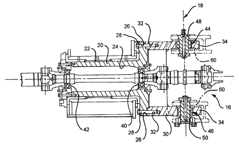
Referring to the drawings, Fig. 1 shows an
articulated machine 10 having a front section 12 and a
rear section 14. The respective sections 12,14 are
linked at articulating hitch 16 for pivoting about
vertical axis 18. Referring now to Figs. 2-4,
articulating hitch 16 includes a cylindrical tube
member 20 and cylindrical yoke member 30. Tube member
has outer and inner surfaces 22,24, opposing ends
and a plurality of fastener holes 26, such as bolt
holes, arranged in a circular pattern on one end. Yoke
15 member 30 likewise has opposing ends and a plurality of
fastener-receiving holes 32, such as bolt-receiving
holes, on one end. Fastener holes 26 and
fastener-receiving holes 32 are axially alignable with
each other. When the tube and yoke members 20,30 are
20 assembled as shown in Fig. 2, fasteners 28, such as
bolts, pass through the fastener holes 26 into the
fastener-receiving holes 32 and securely fasten the
tube and yoke members 20,30 together end to end.
Referring now to Figs. 3-4, the surfaces
22,24 of tube member 20 are preferably made of a
wear-resistant and hardened material, such as forged
steel, to facilitate remanufacture thereof. The inner
surface 24 of tube member 20 is advantageously adapted

CA 02271043 2003-09-12
-8-
for use with bearings 40,42 as are commonly used to
support the drive shaft of an articulated machine.
The yoke member 30 has a trunnion 34 defined
about vertical axis 18. As best shown in Fig. 4,
trunnion 34 includes a first pivot receptacle 44 and a
second pivot receptacle 46, which respectively receive
a first bearing 48 and a second bearing 50 for linking
yoke member 30 to a bifurcated bracket 60 at the front
section 12 of articulated machine 10. Bifurcated
bracket 60 defines a longitudinal bore (not shown) on
front section 12 that is coaxially aligned with
vertical axis 18. As shown in Fig. 2, yoke member 30
additionally has a pair of articulation cylinder bosses
36 on opposing lateral sides of yoke member 30, each
for receiving a steering cylinder (not shown). Yoke
member 30 is advantageously made of cast steel.
Industrial Applicability
In operation, tube member 20 experiences
significantly more wear than yoke member 30. In the
bolt-together hitch 16, because the tube member 20 is
easily separated from the yoke member 30, a new or
remanufactured tube member may replace a worn or
damaged tube member without discarding the yoke member.
Also, the tube member may be replaced while the yoke
member remains on the machine 10. These features offer
significant cost and time savings.
Other aspects, objects and advantages of this
invention can be obtained from a study of the drawings,
the disclosure, and the appended claims.

Representative Drawing
A single figure which represents the drawing illustrating the invention.
Administrative Status

For a clearer understanding of the status of the application/patent presented on this page, the site Disclaimer , as well as the definitions for Patent , Administrative Status , Maintenance Fee  and Payment History  should be consulted.

Administrative Status

Title Date
Forecasted Issue Date 2006-08-01
(86) PCT Filing Date 1998-09-28
(87) PCT Publication Date 1999-04-08
(85) National Entry 1999-04-30
Examination Requested 2003-09-12
(45) Issued 2006-08-01
Deemed Expired 2014-09-30

Abandonment History

There is no abandonment history.

Payment History

Fee Type Anniversary Year Due Date Amount Paid Paid Date
Registration of a document - section 124 $100.00 1999-04-30
Application Fee $300.00 1999-04-30
Maintenance Fee - Application - New Act 2 2000-09-28 $100.00 2000-06-06
Maintenance Fee - Application - New Act 3 2001-09-28 $100.00 2001-06-11
Maintenance Fee - Application - New Act 4 2002-09-30 $100.00 2002-06-25
Maintenance Fee - Application - New Act 5 2003-09-29 $150.00 2003-06-20
Request for Examination $400.00 2003-09-12
Maintenance Fee - Application - New Act 6 2004-09-28 $200.00 2004-06-28
Maintenance Fee - Application - New Act 7 2005-09-28 $200.00 2005-06-23
Final Fee $300.00 2006-05-19
Maintenance Fee - Application - New Act 8 2006-09-28 $200.00 2006-06-23
Maintenance Fee - Patent - New Act 9 2007-09-28 $200.00 2007-08-06
Maintenance Fee - Patent - New Act 10 2008-09-29 $250.00 2008-08-11
Maintenance Fee - Patent - New Act 11 2009-09-28 $250.00 2009-08-07
Maintenance Fee - Patent - New Act 12 2010-09-28 $250.00 2010-08-09
Maintenance Fee - Patent - New Act 13 2011-09-28 $250.00 2011-08-17
Maintenance Fee - Patent - New Act 14 2012-09-28 $250.00 2012-08-29
Owners on Record

Note: Records showing the ownership history in alphabetical order.

Current Owners on Record
CATERPILLAR INC.
Past Owners on Record
FAIRLESS, TERENCE
POLLOCK, ANTHONY J.
Past Owners that do not appear in the "Owners on Record" listing will appear in other documentation within the application.
Documents

To view selected files, please enter reCAPTCHA code :


To view images, click a link in the Document Description column. To download the documents, select one or more checkboxes in the first column and then click the "Download Selected in PDF format (Zip Archive)" or the "Download Selected as Single PDF" button.

List of published and non-published patent-specific documents on the CPD .

If you have any difficulty accessing content, you can call the Client Service Centre at 1-866-997-1936 or send them an e-mail at CIPO Client Service Centre.


Document
Description 
Date
(yyyy-mm-dd) 
Number of pages   Size of Image (KB) 
Representative Drawing 1999-07-29 1 12
Abstract 2003-09-12 1 14
Claims 2003-09-12 6 194
Abstract 1999-04-30 1 50
Description 1999-04-30 5 186
Claims 1999-04-30 2 62
Drawings 1999-04-30 4 113
Cover Page 1999-07-29 1 46
Representative Drawing 2006-01-16 1 17
Description 2003-09-12 8 324
Cover Page 2006-07-05 1 46
Assignment 1999-04-30 6 194
PCT 1999-04-30 3 98
Prosecution-Amendment 2003-09-12 17 573
Correspondence 2006-05-19 1 37