Note: Descriptions are shown in the official language in which they were submitted.
. CA 02271086 1999-OS-OS
r
- 1 -
INGOT MOLD FOR CONTINUOUS CASTING OF MOLTEN METAL,
PARTICULARLY FOR FORMING RECTANGULAR- OR SQUARE-SECTION
STEEL BILLETS
The present invention relates to an ingot mold for
continuous casting of molten metal, particularly for
forming rectangular- or square-section steel billets.
Billets or ingots may be formed from molten metal,
particularly steel, by continuous casting of the molten
metal in a conduit-shaped mold (ingot mold) followed
immediately by rolling (so-called "casting and direct
rolling" technique). While enabling fairly high output
speeds and good-quality products, this technique
currently poses several drawbacks - mainly due to the
process whereby the molten material is cooled and
solidified in the mold - which limit the maximum output
speed obtainable and the range of products that may be
produced from the same mold.
That is, excessively fast casting in a continuous
ingot mold - through which the molten material is cooled
and starts solidifying - is known to result in the
'' . CA 02271086 1999-OS-OS
,. . .
- 2 -
formation of defects in the finished product. More
specifically, cooling, which occurs by the molten
material yielding heat to the walls of the mold, is only
fully effective if the material remains in contact with
the walls, so that a surface laXer of solid metal (so-
called "skin") is formed and gradually increases as the
material travels through the mold. As it solidifies,
however, the material contracts and is detached from the
walls, particularly the inner edges, of the mold, so
that air pockets are formed between the metal skin and
the mold wall, thus reducing the amount of heat given
off, and slowing down the solidification process. The
metal skin (solid layer) therefore continues growing,
except at the corners, where insufficient heat is
subtracted, thus resulting in only partial
solidification of the molten metal and in the formation
of defects in the finished product.
This also increases the likelihood of cracks
forming at the edges, due to undesired stress on the
metal skin as it withdraws from the wall of the mold.
In short, the resulting billet is of poor torsional
strength, is highly susceptible to the formation of
longitudinal cracks along the edges, and has a very
uneven skin temperature, all of which create problems at
the subsequent rolling stage and invariably impair the
quality of the finished product.
To overcome these drawbacks, a relatively low
CA 02271086 1999-OS-OS
- 3 -
casting speed is maintained to enable the material to
' cool as uniformly as possible. Also, reducing the radius
of curvature of the inside corners of the mold is known
to reduce the formation of air pockets, again providing
casting speed is not too high.
When casting only one type of material, detachment
of the metal skin from the mold walls may be reduced by
improving the geometry of 'the mold, e.g. using
appropriately tapered molds. This solution, however,
l0 cannot be applied to molds for producing materials of
different characteristics (e.g. different types of
s teel ) .
Finally, some known molds have a particular, e.g.
concave-walled, section for the passage of the molten
metal. While reducing the problem of~ detachment,
however, this type of mold also fails to provide for
increasing casting speed over and above certain limits.
It is an object of the present invention to provide
an ingot mold for continuous casting of metal materials,
designed to overcome the aforementioned drawbacks
typically associated with known molds. In particular, it
is an object of the invention to provide an ingot mold
enabling effective cooling of the molten metal at all
points and along the whole length of the mold, to
prevent detachment of the metal from the walls, even
from the edges, of the mold, and to enable high-speed
casting of top-quality products allowing of immediate
CA 02271086 1999-OS-OS
"'.
- 4 -
rolling.
According to the present invention, there is
provided an ingot mold for continuous casting of molten
metal, in particular for forming rectangular- or square-
s section steel billets, comprising a longitudinally
elongated casting conduit through which said molten
metal flows and is cooled; said casting conduit having a
substantially rectangular cross section, and being
defined by a first and a second pair of substantially
parallel, side by side walls; said first and said second
pair of walls being substantially perpendicular to one
another, and defining four inner edges; characterized in
that said casting conduit comprises at least a first
portion having rounded inner edges and an inner section
varying gradually from a respective longitudinal first
end, at which said molten metal is fed in, towards a
respective longitudinal second end opposite the first;
said variation in section of said at least a first
portion being determined by a corresponding continuous,
gradual variation in the radius of curvature of said
rounded inner edges; said radius of curvature decreasing
from a maximum value at said first end, to a minimum
value at said second end.
More specifically, said variation in section of
said at least a first portion of said casting conduit is
such as to reproduce a thermal contraction of said
molten metal as it travels through said at least a first
CA 02271086 1999-OS-OS
- 5 -
portion.
The particular design of the ingot mold according
to the present invention provides for effectively
cooling the molten metal at all the surface points, even
at the inner edges, and along the whole length of the
mold. The material, in fact, is maintained contacting
the walls, even at the edges, of the mold at all times,
by virtue of the particular inner section of the
variable-section portion, which in point of fact
reproduces the cooling pattern of the material as it
cools and solidifies.
The metal is thus prevented from detaching from the
walls, even from the edges, of the mold, with no need to
maintain an excessively low casting speed. Cooling
inside the mold according to the invention is so
effective as to enable immediate direct rolling of the
product issuing from the conduit, with no need for any
intermediate processing, by virtue of the material
having the required characteristics (in particular, no
internal stress at the edges, and an even skin
temperature). Moreover, the same mold may be used for
different materials, e.g. for producing different types
of steel, while at the same time ensuring high-quality
products and maintaining a high output speed.
A non-limiting embodiment of the present invention
will be described by way of example with reference to
the accompanying drawings, in which:
CA 02271086 1999-OS-OS
- 6 -
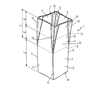
Figure 1 shows a schematic view in perspective of
an ingot mold for continuous casting of molten metal in
accordance with the present invention;
Figure 2 shows a schematic plan view of the molten
metal inlet section of the Figure 1 mold.
In Figures 1 and 2, in~ which the parts are
deliberately shown greatly out of proportion to
highlight the main characteristics of the invention,
number 1 indicates as a whole an ingot mold for
~ continuous casting of molten metal, e.g. steel, in the
form of rectangular-section billets.
Mold 1 comprises a longitudinally elongated casting
conduit 2 through which the molten metal flows; conduit
2 has a substantially rectangular cross section, and is
defined by a first pair 3 and a second pair 4 of
substantially parallel, side by side walls of
predetermined size; and pairs of walls 3 and 4 are
perpendicular to one another and define four edges 5.
In the non-limiting example shown in Figure 1,
conduit 2 is curved, by walls 3 being flat and walls 4
having a predetermined curvature, but may obviously be
of a longitudinal shape other than that described, e.g.
straight. Whichever the case, conduit 2 extends
substantially in a predetermined direction parallel to
the pair of flat walls 3.
According to the present invention, conduit 2
comprises, as of a respective first longitudinal end 7
a
CA 02271086 1999-OS-OS
at which the molten metal is fed in, a first portion 8
with a variable inner section; and a consecutive second
portion 9 with a constant inner section and terminating
at a second end 10 of conduit 2 at which the molten
S metal is fed out. First portion 8 extends longitudinally
by a predetermined length up to ~a respective second end
11 defined by an intermediate section of conduit 2,
which is at once the section at which the molten metal
is fed out of first portion 8, and the section at which
the molten metal is fed into second portion 9.
Edges 5 defined by pairs of walls 3 and 4 are
rounded internally along the whole length of conduit 2;
the radius of curvature of edges 5 varies gradually
along first portion 8, decreasing continuously from a
maximum value R1 at end 7 to a minimum value R2 at the
opposite end il, and maintains a constant value of RZ
along the whole length of second portion 9; and the
selected minimum value R2 of the radius of curvature of
edges 5 is the best value by which to subsequently roll
the metal issuing from casting conduit 2.
The gradual variation in the radius of curvature of
edges 5 along first portion 8 produces a corresponding
gradual variation in the section of portion 8. More
specifically, said variation in section is obtained by
means of respective funnel-shaped portions 12 at the
four edges 5 of portion 8 . the four funnel-shaped
portions 12 project transversely beyond walls 3 and 4,
i
. CA 02271086 1999-OS-OS
extend longitudinally from end 7 to end 11 of portion 8,
and taper towards end 11 of portion 8, which, though
defined by pairs of parallel walls 3 and 4, therefore
has, as stated, an inner section varying longitudinally
and decreasing in area from end 7 to end 11.
At end 11, portion 8 has a rectangular cross
section with no projections and coincident with the
constant section of second portion 9.
The variation in section of first portion 8 is such
as to reproduce the thermal contraction of the metal as
it is fed, and cools, along portion 8. For which
purpose, in a preferred embodiment of the invention, the
variation in section of first portion 8 and the
corresponding variation in the radius of curvature of
inner edges 5 are not linear variations.
Also, the longitudinal extension of variable-
section first portion 8 is preferably roughly equal to
that of constant-section second portion 9. According to
a preferred embodiment, the longitudinal extension of
first portion 8 is less than, e.g. 95~ of, the
longitudinal extension of second portion 9.
In a typical embodiment, purely by way of a non-
limiting example, first portion 8 and second portion 9
have respective lengths Ll - 450 mm and L2 - 600 mm;
which lengths, like all the other distances indicated
below, are measured along an axis parallel to flat walls
3 (as opposed to a longitudinal axis of conduit 2,
a
CA 02271086 1999-OS-OS
- 9 -
which, as stated, may be curved as shown in Figure 1).
As such, the radius of curvature of edges 5 at the
molten metal input end 7 is R1 - 11 mm; at an
intermediate section 13 (Figure 1) of portion 8, at a
distance L3 = 240 mm from end 7 (again measured along an
axis parallel to flat walls 3),'the radius of curvature
assumes an intermediate value of 10.4 mm; and, at end 11
of portion 8 (that is, at a distance L1 - 450 mm from
end 7, or at a distance L4 - 210 mm from intermediate
section 13), the radius of curvature equals minimum
value R2 - 10 mm, which is then maintained along the
whole length of second portion 9 up to the output end 10
of conduit 2. The ratio between the variation in the
radius of curvature and the distance from the molten
metal input end 7 of portion 8 is therefore not constant
along portion 8, but decreases alongside the distance
from end 7 . in the example shown, in which intermediate
section 13 divides portion 8 into a first portion 14 and
a second portion 15 of different lengths, the ratio is
roughly 0.0025 along portion 14 of length L3 - 240 mm
(where the radius of curvature decreases from 11 mm to
10.4 mm), and is roughly 0.002 along portion 15 of
length L4 - 210 mm (where the radius of curvature
decreases further from 10.4 mm to 10 mm).
In this example embodiment, the variation in the
radius of curvature of edges 5, as opposed to being a
linear function of the distance from molten metal input
CA 02271086 1999-OS-OS
- 10 -
end 7 of conduit 2, is obviously such as to reproduce
the variation in section of the molten metal as it cools
(is therefore a function of the thermal contraction of
the metal).
The dimensions of pairs of walls 3 and 4 may
obviously be selected to obtain finished products of
predetermined size. In particular, to form square
section billets, the ratio between the width of flat
walls 3 and the width of curved walls 4 is preferably
1:1.01.
Clearly, changes may be made to the ingot mold as
described above without, however, departing from the
scope of the accompanying Claims.