Note: Descriptions are shown in the official language in which they were submitted.
CA 02271127 2003-09-22
-1-
FIBRE BRAGG GRATINGS IN CHALCOGENIDE OR
CHALCOHALID BASED INFRARED OPTICAL FIBRES
BACKGROUND OF THE INVENTION
1. Field of the Invention
The present invention relates to fibre Bragg gratings and more particularly to
a
method of writing fibre Bragg gratings in infrared transmitting chalcogenide-
based or
chalcohalide-based fibres.
to
2. Description of Related Art
Since the discovery and description of photodarkening in chalcogenide glasses
in 1971 by Berkes et al. ("Photodecomposition of Amorphous As2Se3 and As2S3".
J.
Appl. Phys. Vol. 42, No. 12, pp. 4908-4916, Nov. 1971 ), much effort has been
put
~s forth to understand the detailed mechanisms of this effect. Sulphide based
chalcogenide glass, specifically arsenic sulphide (As2S3), exhibits a wealth
of
interesting permanent and reversible photoinduced changes when illuminated
with
light that has an energy near the Tauc gap of 2.3 eV. These changes include
photodarkening, and photoinduced birefringence and dichroism. Photodarkening
is
2o discussed in "Mechanisms of Photodarkening in Amorphous Chalcogenides", K.
Tanaka, Journal of Non-Crystalline Solids, Vol. 59-60, Part II, pp 925-928,
(1983).
Photoinduced birefringence and dichroism are discussed at greater length in
"Photoinduced Optical Anisotropy in Chalcogenide Vitreous Semiconducting
Films",
V. G. Zhdanov et al., Physica Status Solidi (a), Vo1.52, No. 1, pp 621-626,
(March
2s 1979) and in "Anisotropy of Photoinduced Light-Scattering in Glassy As2S3",
V.
Lyubin et al., Journal of Non-Crystalline Solids, Vols. 164-166, pp 1165-1168,
North-
Holland (1993).
Although a unified theoretical microscopic description of these effects is not
complete, it is believed that photodarkening is produced as carriers break As-
S bonds
3o when they recombine, causing an increase in As-As and S-S
CA 02271127 2003-09-22
-2-
bonding, which in turn causes a lowering of the band-gap energy by as much as
0.05
eV at room temperature. (See "The Origin of Photo-Induced Optical
Anisotrophies in
Chalcogenide Glasses", H. Fritzsche, Journal of Non-Crystalline Solids, Vols.
164-
166, pp. 1169-1172, North Holland, 1993.) Since only a finite number of As-S
bonds
s have a local environment which allows this process to happen, the effect
saturates
with total illumination energy. Regardless of the model, however, these
effects are
experimentally well characterized: the total refractive index change at 600 nm
is about
0.01. (See "Photodarkening Profiles and Kinetics in Chalcogenide Glasses", S.
Ducharme et al., Physical Review B, Vol. 41, No.17, pp. 12 250 - 12 259, 15
June
Io 1990.) A simple Kramers-Kronig analysis predicts that this index change
will decrease
linearly with photon energy in the transparent region of the glass, thus
allowing large
amplitudes (On ~ 10-3) to be induced in the infrared.
The technique of side writing fibber Bragg gratings in germanium-doped silica
fibres is well established and was first described by Meltz, et al.
("Formation of Bragg
is Gratings in Optical Fibres By A Transverse Holographic Method", Optics
Letters, Vol.
14, No. 15, pp 823-825, Aug. 1989.) Two "writing" beams are crossed at some
angle
8, with the intersection point coinciding with the core of the silica fibre.
The crossed
beams form an intensity grating along the axis of the fibre with period
A=~W/(2 sinA)
,where Aw is the wavelength and 8 is the half angle between the writing beams,
2o respectively. The writing beams change an absorption line due to the
germanium
doping of the core, causing a change An in the index of refraction n at lower
photon
energies. The index change amplitude is around On~10-5-10-6 for silica glass.
This
grating forms a Bragg reflector at the vacuum wavelength lie for light
launched down
the core of the fibre at aB=2nA. The "photonic band gap" energy, OvB, which
2s corresponds to the full-width of the reflectance between the first two
zeros of the
reflectivity, is OvB/vB=~n/n where VB=c/~B" and c is the speed of light. See
"Propagation Through Nonuniform Grating Structures", J.
CA 02271127 2003-09-22
-3-
E. Sipe et al., J. Opt. Soc. A,. A, Vol. 11, No. 4, pp.1307-1320 (April 1994).
It has been previously demonstrated by Shiramine et al. ("Photoinduced Bragg
Reflector In As2S3 Glass", Appl. Phys. Lett., Vol. 64 (14), pp 1771-1773, 4
April 1994)
that Hill gratings may be written in As2S3 glass flakes. Hill gratings are
formed from
s absorption of the peaks of the standing wave produced by multiple
reflections from
parallel end-surfaces. (See "Photosensitivity In Optical Fibre Waveguides:
Application
To Reflection Filter Fabrication", K. C. Hill et al., A ph. I. Phys. Lett.,
Vol. 32 (10), pp.
647-649, 15 May 1978.) The period of the standing wave sets the Bragg
reflection
condition, which gives a reflection maximum at the wavelength of the writing
beam.
to Since the energy of the writing beam needs to be near the Tauc gap in order
to
photoinduce carriers, Hill-gratings will not be useful at infrared wavelengths
which are
not significantly absorbed in the material.
SUMMARY OF THE INVENTION
Is It is therefore an object of the invention to provide variable-bandwidth,
high
reflectance fibre Bragg gratings for mid-infrared integrated optics
applications.
Another object of the invention is to write reflective Bragg gratings into
infrared
transmitting fibres.
Another object of the invention is to side write fibre Bragg gratings into
infrared
2o transmitting fibres.
Another object of the invention is to provide fibre Bragg gratings in
chalcogenide or chalcohalide-based infrared optical fibres with reflectances
peaked at
one or more wavelengths between 1.5 and 15 microns in the infrared.
A further object of the invention is to side write highly-reflective, fibre
Bragg
2s gratings into sulphide-based chalcogenide infrared optical fibres.
A further object of the invention is to provide fibre Bragg gratings in
infrared
transmitting sulphide-based fibres.
These and other objects of this invention are achieved by forming reflective
fibre Bragg gratings in the interior of an infrared transmitting glass fibre,
such as a
CA 02271127 2004-03-O1
-4-
chalcogenide or chalcohallde-based infrared optical fibre, by side
illuminating the
fiber with two same-wavelength, laser writing beams which intersect at some
anglE
in the fiber to form an intensity grating by way of interference along the
length of
the fiber at the intersection of the two writing beams to produce a reflective
Bragg
grating in the core and cladding of the glass fiber, and repeating this
operation for
each reflective fiber Bragg grating that is desired.
According to a first aspect of the invention, there is provided a method of
fabricating at least two reflective Bragg gratings in the interior of an
infrared
transmitting glass fiber wherein the gratings can be written using laser
diodes and
the grating formation mechanism is not dopant-reliant, said method comprising
the
steps of:
(a) producing first and second writing beam lines at the same wavelength;
(b) orienting the first and second writing beam lines in parallel with respect
to each other;
(c) crossing the first and second writing beam lines at a preselected angle
with respect to each other tv form an interference pattern at the intersection
of the
first and second writing beam lines;
(d) positioning a first part of the infrared transmitting glass fiber at the
intersection of the first and second writing beam lines so that the
interference
2n pattern occurs along a first portion of the length of the infrared
transmitting glass
fiber;
(e) maintaining the first part of the infrared transmitting glass fiber at the
intersection of the first and second writing beam lines for a time sufficient
to
produce a first Bragg grating in the core and of the infrared transmitting
glass fiber;
(f) positioning a second part of the infrared transmitting glass fiber at the
intersection of the first and second writing beam lines so that the
interference
pattern occurs along a second portion of the length of the infrared
transmitting
glass fiber; and
(g) maintaining the second part of the infrared transmitting glass fiber at
the
3U intersection of the first and second writing beam lines far a time
sufflclent to
produce a second Bragg grating in the core and cladding of the infrared
transmitting glass fiber;
wherein the wavelength of the first and second writing beams is within the
CA 02271127 2004-03-O1
-4a-
range from about 0.5 ~,m to about 1.5 ~,m in order to produce a Bragg
reflection
grating having an operative wavelength in the range between 1.5 ~.m to about
15
~,m.
According to a second aspect of the invention, there is provided the optical
fiber made according to the above-described method.
According to a third aspect of the invention, there is provided a method of
forming an optical grating in an optical fiber wherein the gratings can be
written
using laser diodes and the grating formation mechanism is not dopant-reliant,
said
grating being constituted by variations in the index of refraction in said
optical
fiber, comprising:
providing said optical fiber, said fiber comprising optical material that is
either chalcogenide or chalcohalide;
producing a pair of writing beams of the same preselected frequency,
wherein said preselected frequency is within the range of frequencies
corresponding to wavelengths in the range of 0.5 ~.m to 1.5 ~.m;
directing said beams to cross one another and placing said optical fiber at
the intersection point where said beams cross one another effectively to form
an
interference pattern with one another within said optical material, thereby
obtaining
a Bragg reflection wavelength in the range between 1.5 ~m to 15 pm; and
maintaining said interference pattern sufficiently long to permit said pattern
to form said grating by forming variations in the index of refraction within
said
material corresponding to said pattern.
According to a fourth aspect of the invention, there is provided an optical
fiber made according to the above-described method.
According to a fifth aspect of the invention, there is provided an apparatus
for forming an optical grating in an optical fiber wherein the gratings can be
written
using laser diodes and the grating formation mechanism is not dopant-reliant,
said
grating being constituted by variations in the index of refraction in said
optical
fiber, comprising:
an optical material that is either chalcogenide or chalcohalide;
an optical source effective to produce a pair of writing beams of the same
preselected frequency, wherein said preselected frequency is within the range
of
CA 02271127 2004-03-O1
-4b-
frequencies corresponding to wavelengths between about 0.5 to 1.5 wm, thereby
obtaining a Bragg reflection grating having an operative wavelength in the
range
between 1.5 ~,m to 15 Vim; and said source is disposed to cause said beams to
cross one another effective to form an interference pattern with one another
within
said material by placing said optical fiber at the intersection point where
said
beams cross one another;
wherein said source and said means for directing are adapted to cooperate
effectively to maintain said interference pattern sufficiently long to permit
said
pattern to form said grating by causing variations in the index of refraction
within
said material corresponding to said pattern.
According to a sixth aspect of the invention, there is provided a method of
fabricating a reflective Bragg grating in the interior of an infrared
transmitting glass
fiber, said method comprising the steps of:
producing first and second writing beams at the same wavelength;
orienting the first and second writing beams in parallel with respect to each
other;
crossing the first and second writing beams at a preselected angle with
respect to each other to form an interference pattern at the intersection of
the first
and second writing beams;
positioning the infrared transmitting glass fiber at the intersection of the
first
and second writing beams so that the interference pattern occurs along a
portion
of the length of the infrared transmitting glass fiber; and
maintaining the infrared transmitting glass fiber at the intersection of the
first and second writing beams for a time sufficient to produce a Bragg
grating in
the core and cladding of the infrared transmitting glass fiber;
wherein the infrared transmitting glass fiber is selected from the group
consisting of any chalcogenide-based fiber and any chalcohalide-based fiber;
and
wherein said first and second writing beams have a wavelength within the
range from about 0.5 ~,m to about 1.5 ~,m, thereby obtaining a Bragg
reflection
grating having an operative wavelength in the range between 1.5 ~,m to 15 ~,m.
CA 02271127 2003-09-22
- S -
BRIEF DESCRIPTION OF THE DRAWINGS
These and other objects, features and advantages of the invention, as well as
the invention itself, will become better understood by reference to the
following
detailed description when considered in connection with the accompanying
drawings
s wherein like reference numerals designate identical or corresponding parts
throughout the several views and wherein:
Fig. 1 illustrates a simplified schematic diagram of a reflective fibre Bragg
grating side-written into a sulphide-based chalcogenide infrared optical fibre
and
further indicates a method for side-writing the grating into the sulphide-
based
Io chalcogenide infrared optical fibre;
Fig. 2 illustrates exemplary fibre material compositions of chalcogenide and
chaicohalide based infrared optical fibres;
Fig. 3 illustrates the Bragg reflection wavelength I~B verses the writing
angle 8W
for three typical writing wavelengths hW and
Is Fig. 4 illustrates a schematic diagram of an experiment which demonstrated
the side-writing of a fibre Bragg grating in an arsenic sulphide-based
chalcogenide
infrared optical fibre.
DETAILED DESCRIPTION OF THE PREFERRED EMBODIMENT
2o Before explaining the structure and operation of applicants' invention, it
should
be noted that applicants have written Bragg gratings into both core only
multimode
sulphide fibre (AS4pS5gSe5, 300-Nm diameter) and a core-clad multimode
sulphide
fibre (As4oS55Se5, 200 pm core diameter, As4oS55Se5, 300 Nm clad diameter).
Thus, it
should be understood that the fibres in which gratings can be written in this
invention
2s can be core only (a single composition of glass) or core-clad (two
concentric
compositions of glass, where the core index is higher than the cladding
index.)
Referring now to the drawings, Fig. 1 illustrates a simplified schematic
diagram
of a reflective fibre Bragg grating side-written into a sulphide-based
chalcogenide
infrared optical fibre and further indicates a method for
CA 02271127 2003-09-22
-6-
side-writing the grating into the sulphide-based chalcogenide infrared optical
fibre.
As shown in Fig. 1, two exemplary laser beams at the same writing wavelength
are used as input "writing" beams 11 and 13. These two writing beams 11 and 13
are
crossed at some angle 8; in space.
s A chalcogenide- or chalcohalide- based glass (Fig. 2) infrared transmitting
optical fibre, such as a sulphide-based fibre 15 having a core 17 and a
cladding 19, is
placed at the intersection point where the two writing beams 11 and 13 cross
in space
such that where the beams 11 and 13 cross coincides with the fibre 15 itself-
the fibre
core 17 and cladding 19. The crossed beams 11 and 13 form an interference
pattern
to or intensity grating 21 along the axis of the fibre 15 itself with period
A=hw/(2 sinA),
where AW is the writing wavelength and A; is the half-angle between the
writing beams
11 and 13. The writing wavelength hw is in the range of 0.5 Nm to 1.5 Nm. This
wavelength is chosen to have an absorption length in the particular glass
composition
of the fibre 15 such that it is weakly absorbed in the glass. Weakly absorbed
is
Is defined as an absorption of between 0.1 and 10 cm-'. For example, this
would
correspond to a wavelength in the range of 0.5 pm - 0.8 Nm in the As4oSso
glass
composition, and a wavelength range of 0.8 Nm - 1.4 Nm in the Ge33As~2Se55
composition.
When the two crossed beams 11 and 13 are left on the fibre 15 for a
2o predetermined length of time, such as an exemplary three or four minutes,
the
interference pattern 21 in the fibre 15 produces an index change in the glass,
causing
a change An in the index of refraction n at lower photon energies. The range
of An,
induced by the crossed beams 11 and 13 at Aw is between 0 and 0.2. It should
be
noted at this time that the typical range of writing fluences at J~"" is
between 0.1 and
as 100 W/cm2, and will be incident from 0-1000 minutes. Any writing
fluence/temporal
duration of writing sufficient to write a On consistent with the above
specified 0 to 0.2
range of an 0n induced by the crossed beams 11 and 13 at ~w is intended to be
covered by the claimed invention.
CA 02271127 2003-09-22
The grating produced by the two writing beams 11 and 13 forms a Bragg
reflector at the vacuum wavelength AB for light launched down the core of the
fibre at
AB=2nA. The "photonic band gap" energy, OvB, which corresponds to the full-
width of
the reflectance between the first two zeros of the reflectivity, is wB/vB=On/n
where
s vB=c/J~B" and c is the speed of light.
So the change in the index of refraction will go higher and lower periodically
in
space along the length of the fibre 15, essentially producing a multi-stack
mirror (not
shown). The wavelength at which the mirror reflects depends on the period of
that
grating which can be changed by changing the angle 8; between the beams 11 and
io 13. (To be discussed in regard to Fig. 3.)
When it is desired to determine the wavelength at which reflecting occurs, an
infrared beam can be injected into the core 17 of the fibre 15 and the writing
wavelength of the beams 11 and 13 can be changed until a wavelength is
reflected
from the fibre 15. That reflected wavelength is called the Bragg wavelength or
the
is Bragg reflection wavelength hB. The Bragg reflection wavelength hB is in
the infrared
region from 1.5 pm - 15 pm. The necessary writing angles and wavelengths to
achieve a desired Bragg reflection wavelength are shown and discussed in
relation to
Fig. 3.
The mechanism for writing a photo-induced index change is based on
2o rearranging the local bonding structure of the intrinsic atoms of the
chalcogenide-
based or chalcohalide-based glass used in the infrared optical fibres. No
dopants are
used or required for the photoinduced index change.
The fibre materials covered by this application are all chalcogenide and
chalcohalide glasses where an index change can be photoinduced with a writing
2s wavelength l~"~, using the mechanism described in the previous paragraph.
Components of exemplary fibre material glass compositions of chalcogenide-
based
infrared optical fibres are shown in Fig. 2A, while components of exemplary
fibre
glass compositions of chalcohalide-based infrared optical fibres are shown in
Fig. 2B.
CA 02271127 2003-09-22
g
As indicated in Fig. 2A, the calcogenide glass compositions include any glass
composed of at least one of the anions sulphur (S), selenium (Se) and
tellurium (Te)
and at least one suitable cation, including but not limited to barium (Ba),
germanium
(Ge), indium (In), arsenic (As), gallium (Ga), or lanthanium (La) in binary,
ternary,
s quaternary, etc. mixtures. Example chalcogenide glass compositions include
As4oSso,
AS4pS55se5, and Ge33AS12Se55.
As indicated in Fig. 2B, the chalcohalide glass compositions include any glass
composed of at least one of each of the aforementioned cations and anions,
plus at
least one of the halides (but less than a total of 50 weight percent) of
chlorine (CI),
~o fluorine (F), bromine (Br) and iodine (I).
It is intended that all compositions of the chalcogenide and chalcohalide
glasses that form a stable glass and exhibit photoinduced index changes are
included
in the claimed invention.
Referring now to Fig. 3, Fig. 3 illustrates the Bragg reflection wavelength hB
Is verses the writing angle 6w for three typical writing wavelengths IoW. The
angle of 6W
on the X-axis of Fig. 3 corresponds to the angle 8; between the writing beams
11 and
13 that are incident upon the fibre 15 in Fig. 1. Fig. 3 indicates that upon
choosing a
given A"" angle along the X-axis for one of the three typical writing
wavelengths
shown in Fig. 3, an associated Bragg reflection wavelength will be indicated
on the Y-
2o axis. For example, if a writing wavelength of about 532 nm, which
corresponds to a
frequency doubled Nd:YAG laser, were selected and an 8w angle of 30°
were
Chosen, Fig. 3 would indicate that a Bragg reflection wavelength of about 2.4
microns
would result. So as indicated in the curve of Fig. 3, as the 8w angle gets
smaller as
the left-hand side of the curve is approached down to 0°, the Bragg
wavelength
2s increases to longer and longer wavelengths hB. Thus, if it were desired to
write a
Bragg grating at, for example, 10 microns, it can be seen that the 10 on the Y-
axis
would correspond to a 6"" angle of
CA 02271127 2003-09-22
-9-
about 10°. So if 10° were put on the angle shown in Fig. 3, Fig.
3 would correspond to
Fig. 1.
Three different curves are shown in Fig. 3. The three different curves
correspond to three different writing wavelengths which would be crossed in
Fig. 1.
s Pairs of beams would be. derived from the same laser. The lowest curve 23
corresponds to a wavelength of 532 nm from an exemplary frequency doubled
Nd:YAG. The center curve 25 corresponds to a 632 nm wavelength from a helium-
neon laser. And the upper curve 27 corresponds to a 1.064 Nm wavelength from a
Nd:YAG laser. From Fig. 3, it can be readily seen that the angle necessary to
write a
to given reflectivity gets wider with longer wavelengths. A different writing
wavelength
may be required to write in infrared fibres having different compositions in
order to
make sure that the radiation from a laser is completely absorbed in the glass
of the
infrared transmitting fibre.
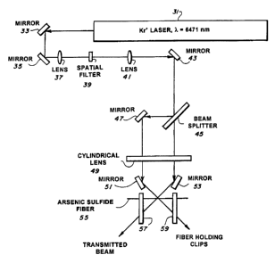
Referring now to Fig. 4, a schematic diagram of an experiment which
~s demonstrated the side-writing of a fibre Bragg grating in an arsenic
sulphide-based
chalcogenide infrared optical fibre is shown. As shown in Fig. 4, a krypton
ion laser 31
transmits a 40 mW CW beam at a wavelength ~=647.1 nm (or 0.6471 pm). The
transmitted beam is sequentially reflected by two mirrors 33 and 35 so that
the beam
can be focused down to a small point by a lens 37.
2o The focused beam from the lens 37 is passed through a spatial filter 39
which
basically is just a pinhole (not shown) in a piece of metal to clean up the
beam. The
pinhole can be about an exemplary 100 microns in diameter, depending on the
size
of the lens 37 being used. Any irregularities in the shape of the beam or
distortions
caused by, for example, dust will not focus to a nice fine point of light that
will readily
2s pass through the pinhole in the spatial filter 39 but will be blocked by
the spatial filter
39. The only light that comes through the pinhole in the spatial filter 39 is
basically a
perfect beam which starts to diverge as it exits the pinhole. The diverging
beam that
is exiting the pinhole in the spatial filter 39 is collimated by a lens 41.
The lenses 37
and 41 and the
CA 02271127 2003-09-22
- 1~ -
spatial filter 39 operate together to make the beam at the output of the lens
41 round
and clean-shaped.
The collimated beam from the lens 41 is reflected by a mirror 43 to a
beamsplitter 45 in the part of the experiment that actually writes the
grating. The
s beam splitter 45 reflects half of the power or 20 mW to another mirror 47
which, in
turn, reflects the light to a cylindrical lens 49. The beam splitter 45 passes
the other
half of the power or 20 mW therethrough to the cylindrical lens 49. Thus,
essentially
two parallel 20 mW light beams are applied to the cylindrical lens 49. The
cylindrical
lens 49 begins to focus each of the two beams in only one direction down to a
to relatively long and thin line.
As the beams are focusing, they are redirected toward each other by flat
mirrors 51 and 53 to cross at an angle A. The beams look like lines at the
point where
they cross in space at the focus. It is at that point in space where an
arsenic sulphide
fibre 55 is placed and held in position by fibre holding clips 57 and 59 while
at least
is one Bragg grating is being written into the fibre 55. In a useful device, a
single mode
fibre would preferably be used with the core size of the fibre being very
small, such as
an exemplary 10 microns in diameter.
The two beams cross at an angle 8 along the core of the arsenic sulphide fibre
55 so that a Bragg grating can be written into the fibre 55.
2o The arsenic sulphide fibre transmits most of the 0.6471 Nm light which is
incident on the side of the fibre 55. This light emerges as from a very strong
cylindrical lens in two opposing "arc" shaped patterns. Each beam also has a
visible
reflection from the surface of the fibre. To get the alignment correct, these
directions
of the "arc" shaped reflections off the fibre are matched with the
complementary input
2s beam to assure that the beams overlap in the fibre core.
It was determined that about 3 minutes of illumination with 20 mW in each
writing beam (for a 3mm long grating) was sufficient to saturate the amplitude
of the
photoinduced index change. The fact that a large amplitude Bragg grating was
written
in the fibre was verified by blocking one of the
CA 02271127 2003-09-22
- 11 -
writing beams after the beams were incident for several minutes. As one beam
is
blocked, a large portion of the other beam is diffracted into the blocked-
beam's
direction which was clearly visible to the naked eye with normal room lighting
present.
s ADVANTAGES AND NEW FEATURES OF THE INVENTION
There are two new features of the invention. The first key new feature is that
~B
is now in the IR region of 1.5 - 15 Nm. The second new key feature is that the
mechanism of making 0n does not depend on any dopant(s) to be present in the
glass material. Also, when light is sent down the core of a single-mode
sulphide fibre,
to it will be reflected by this Bragg grating. Unlike silica fibre Bragg
gratings, however,
the index-change amplitude of these gratings is larger by two orders of
magnitude,
allowing the possibility of constructing highly reflective, wide band
structures.
Also, since the writing wavelength is around 650 nm, the writing could be done
in principle with commercially available pulsed or continuous-wave laser
diodes,
is eliminating the need for an expensive and unwieldy excimer or krypton
laser.
ALTERNATIVES
The writing process depends only on the total number of photoinduced carriers
which subsequently recombine in the illuminated area. This suggests that the
fibres
2o may be written with short pulses which inject the same total number of
carriers. This
will allow very fast writing of a single grating, similar to the process
already in use with
silica fibres. See "Fibre Bragg Reflectors Prepared By A Single Excimer
Pulse", C. G.
Askins et al., Optics Letters, Vol. 17, No. 11, pp. 833-835, (June 1, 1992).
In addition, fibre Bragg gratings can be written via the same method and using
Zs the same physical process in other fibre compositions. This photodarkening
effect
occurs in any chalcogenide or chalcohalide based fibres, including fibre
compositions
containing the chalcogens sulphur, tellurium, and selenium, and mixtures of
the
aforementioned chalcogens with halides such as fluorine and chlorine.
CA 02271127 2003-09-22
-12-
Fibre Bragg gratings can also be written in chalcogenide fibres which are
doped with rare-earths such as erbium and praesodymium, which will allow
mirror
integration in laser and laser amplifier devices based on these materials.
Therefore, what has been described in a preferred embodiment of the
s invention is a method, and the resultant device, for forming at least one
reflective fibre
Bragg grating in the interior of an infrared transmitting glass fibre, such as
a
chalcogenide or chalcohalide-based infrared optical fibre, by side
illuminating the fibre
with two same-wavelength, laser writing beams which intersect at some angle in
the
fibre to form an intensity grating by way of interference along the length of
the fibre,
to maintaining the infrared transmitting glass fibre at the intersection of
the two writing
beams to produce a reflective Bragg grating in the core and cladding of the
glass
fibre, and repeating this operation for each reflective fibre Bragg grating
that is
desired.
It should therefore readily be understood that many modifications and
Is variations of the present invention are possible within the purview of the
claimed
invention. For example, the laser 31 could be replaced with a different laser
to
develop a different writing wavelength, such as a Nd:YAG laser which emits at
1064
nm, a doubled Nd:YAG laser which emits at 532 nm, or preferably with a helium
neon
laser which emits at 632 nm. The output power of the laser such be limited to,
for
2o example about 40 mW to avoid burning the fibre 55 that a Bragg grating is
being
written into. Similarly, the fibre 55 could be replaced with any chalcogenide
or
chalcohalide infrared transmitting fibre having a composition selected
according to
the discussion in relation Figs. 2A and 2B. Furthermore, it should be noted
that the
optical section of Fig. 4, which is shown being comprised of the exemplary
2s combination of mirrors 33, 35 and 43, lenses 37 and 41 and the spatial
filter 39, could
be simplified and/or replaced with any other combination of optical components
to
direct and split the output of the laser 31 into two substantially equal power
beams
befo re
CA 02271127 2003-09-22
-13-
applying those beams to the cylindrical lens 49. For example, the laser beam
from the
laser 31 could be directly applied to the beam splitter 45. It is therefore to
be
understood that the invention may be practiced otherwise than as specifically
described.