Note: Descriptions are shown in the official language in which they were submitted.
CA 02271137 1999-OS-06
WO 98/46422 PCT/US98/00586
IMPACT AND PUNCTURE RESISTANT PANELS
CROSS-REFERENCE TO RELATED APPLICATIONS
TECHNICAL FIELD AND
INDUSTRIAL APPLICABILITY OF THE INVENTION
The present invention relates to impact and puncture resistant panels and,
more particularly, to impact and puncture resistant panels formed from strand
material
which includes reinforcing fibers and polymeric material.
BACKGROUND OF THE INVENTION
Impact and puncture resistant panels are useful in many applications,
including as protective coverings for cash windows of financial institutions,
coverings for
kiosks and carts in open areas of shopping malls, side panels for tractor
trailers, boat hulls,
aircraft parts and other articles and parts for which impact resistance and/or
puncture
resistance are desired. By way of example only, the prior use of such panels
as shutters or
window covers shall now be described. Buildings and houses located in areas
prone to
severe weather conditions, such as hurricanes and tornados, are often exposed
to wind
borne debris during those severe weather conditions. Windows and doors,
especially
those made of glass, are most vulnerable to wind borne debris, such as tree
branches,
rocks and portions of surrounding structures.
Shutters made of aluminum and steel are currently used to protect
vulnerable portions of buildings and houses because shutters made from these
materials
can be manufactured to meet building and housing codes in regions which
experience
severe weather conditions. However, steel and even aluminum shutters undergo
pitting
and strength degradation associated with corrosion, particularly in regions
along the sea
coast, where the air contains a high concentration of corrosive salt. In
addition, metal
shutters can be somewhat heavy.
Accordingly, there is a particular need for an impact and puncture resistant
panel which can prevent the penetration of wind borne debris during severe
weather
conditions, is corrosion resistant and is relatively lightweight. There is
also a more
CA 02271137 1999-05-06
WO 98/46422 PCT/US98/00586
general need for an impact and puncture resistant panel that is relatively
inexpensive to
produce and readily adapted to various applications and strength requirements.
SUMMARY OF THE INVENTION
The present invention satisfies the current needs in the art by providing a
panel precursor which can be used to produce an impact and puncture resistant
panel,
having a fiber reinforced polymeric matrix, which is relatively resistant to
penetration,
inexpensive, corrosion resistant and lightweight.
The impact and puncture resistant panels of the present invention are
formed using a panel precursor comprising a plurality of laminae. Each of the
laminae
comprises a plurality of strands, with each strand comprising a plurality of
fibers,
including reinforcing fibers, and at least one polymeric material. The
polymeric material
forms all, substantially all, or at least part, of the matrix for the panel.
All of the matrix
refers to the polymeric material from the strands providing all of the matrix
except for that
formed by any chemical treatment that may have been applied to the reinforcing
fibers or
any fiber made from the polymeric material. Substantially all refers to the
polymeric
material from the strands being enough to provide a matrix for a11 of the
reinforcing fibers
of the panel. It does not preclude the use of additional matrix material from
a source other
than the strands. A portion of the polymeric material of each of the laminae
is fused to a
portion of the polymeric material of another of the laminae so as to join the
laminae
together.
In one embodiment, the plurality of laminae comprises a first lamina and a
second lamina. Each of the laminae has a first plurality of the strands
forming a first layer
of strands and a second plurality of the strands forming a second layer of
strands. A
portion of the polymeric material from the first plurality of the strands is
fused to a
portion of the polymeric material from the second plurality of the strands so
as to join the
first plurality of the strands in an angular relation to the second plurality
of the strands.
Additionally, a portion of the polymeric material from the first lamina is
fused to a
portion of the polymeric material from the second lamina so as to join the
first lamina at
an angle to the second lamina.
In another embodiment, the plurality of laminae comprises a first lamina
and a second lamina. Each of the laminae has a plurality of the strands woven
together.
-2-
CA 02271137 1999-OS-06
WO 98l46422 PCT/US98/00586
A portion of the polymeric material from the first lamina is fused to a
portion of the
polymeric material from the second lamina so as to join the strands of the
first lamina in
an angular relation to the strands of the second lamina. It may be desirable
for a panel of
the present invention to include lamina from each of the above two exemplary
S embodiments.
The invention is also directed to an impact and puncture resistant shutter
comprising a plurality of panels operatively adapted for being secured to the
exterior of a
building. Each of the panels is produced using the present panel precursors.
The objectives, features and advantages of the present invention will
become apparent upon consideration of the following detailed description,
accompanying
drawings and appended claims.
BRIEF DESCRIPTION OF THE DRAWINGS
Fig. 1 presents a cutaway view showing the laminae of a panel formed
according to one embodiment of this invention.
Fig. 2 presents a cutaway view showing the laminae of a panel formed
according to another embodiment of this invention.
Fig. 3 present a cutaway view of a modification of the panel of Fig. 2.
Fig. 4 presents a perspective view of a plurality of panels of this invention
in the form of a shutter.
Fig. 4A presents a sectional view of the shutter shown in Fig. 4, taken
along lines 4A-4A.
Fig. S presents a perspective view of a plurality of panels of this invention
in the form of an alternate shutter.
Fig. SA presents a sectional view of the shutter of Fig. 5, taken along lines
SA-SA.
Fig. 6 presents a perspective view of a plurality of panels of this invention
in the form of a window covering.
Fig. 6A presents an enlarged view of a portion of Fig. 6 showing the
manner in which the window covering of Fig. 6 can be attached to a wall.
Fig. 6B presents a sectional side view of a latch mechanism that can be
used to attach the window covering of Fig. 6 to a wall.
-3-
CA 02271137 1999-OS-06
WO 98/46422 PCT/US98/00586
Fig. 7 presents a perspective view of a plurality of panels of this invention
in the form of another alternate shutter.
Fig. 7A presents a sectional view of the shutter shown in Fig. 7, taken
along lines 7A-7A.
Fig. 8 presents a perspective view of a plurality of panels of this invention
in the form of an additional alternate shutter.
Fig. 8A presents a sectional view of the shutter shown in Fig. 8, taken
along lines 8A-8A.
DETAILED DESCRIPTION AND
PREFERRED EMBODIMENTS OF THE INVENTION
The present invention is directed to an impact and puncture resistant panel
10. The present panel 10 is a lamination comprising a plurality of laminae 12,
each of
which is formed from a plurality of reinforcement strands 16. Each strand 16
includes a
plurality of reinforcing fibers 17 and at least one polymeric material 19.
Useful
reinforcing fibers can be any suitable reinforcing fiber including those
selected from the
group consisting of E-glass fibers, S-glass fibers, graphite fibers, aramid
fibers, silicon
carbide fibers, other fibers having suitable reinforcing characteristics and
various
combinations thereof. The polymeric material 19 can be any suitable polymeric
material
including a thermoplastic polymeric material selected from the group
consisting of
polyamides, polypropylenes, polyesters, polyethylenes, polyphenylene sulfides
and other
like thermoplastic materials.
The polymeric material 19 may be in the form of polymeric fibers which
are commingled or combined with one or more reinforcing fibers 17 to form the
strands
16. Methods for making commingled reinforcing and polymer fiber strands are
disclosed
in detail in copending U.S. Patent Application Serial No. 08/31 l,817 filed
September 26,
1994 (Attorney Docket 23422A) and entitled "METHOD AND APPARATUS FOR
FORMING COMPOSITE STRANDS," by Andrew B. Woodside et al. The applicants
hereby incorporate by reference the '817 application in its entirety. If
commingled
reinforcing-polymer fibers are used, it is desirable, though not required, for
the weight
ratio of reinforcing fibers to polymer fibers to range from about 40/60 to
about 60/40. It
-4~
CA 02271137 1999-OS-06
WO 98/46422 PCT/US98/00586
can be more desirable for the weight ratio of reinforcing fibers to polymer
fibers to be
about 50:50.
Alternatively, the strands 16 may comprise a plurality of the reinforcing
fibers 17 with the polymeric material 19 wire-coating or otherwise forming a
layer around
the reinforcing fibers 17 of each strand 16. These coated strands 16 may also
include
fibers made of the polymeric material 19 that are commingled with the
reinforcing fibers
17. In addition, it may be desirable to use any combination of the above
described strands
16 in making a panel 10 according to the present invention. Examples of such
strands 16
are disclosed in copending U.S. Patent Application Serial No. 08/695,909,
filed
August 12, 1996, and entitled "CHEMICAL TREATMENTS FOR FIBERS AND WIRE-
COATED COMPOSITE STRANDS FOR MOLDING FIBER-REINFORCED
THERMOPLASTIC COMPOSITE ARTICLES," by Andrew B. Woodside, and in
copending U.S. Patent Application Serial No. 08/695,504, filed August 12,
1996, and
entitled "CHEMICAL TREATMENTS FOR FIBERS AND WIRE-COATED
COMPOSITE STRANDS FOR MOLDING FIBER-REINFORCED THERMOPLASTIC
COMPOSITE ARTICLES," by Andrew B. Woodside, the disclosures of which are
hereby
incorporated by reference.
Whether the strands 16 are formed by wire coating, commingling
reinforcing and polymer fibers, or a combination thereof, it may or may not be
desirable
for the resulting strands 16 to be sized, impregnated or preimpregnated with a
suitable
chemical treatment. The cohesiveness of the fibers forming each of the strands
16 may be
maintained by means of a suitable aqueous, nonaqueous, or solvent free
chemical .
treatment. The chemical treatment can be applied so as to size the fibers
before they are
formed into a strand 16. However, to insure the cohesiveness of the fibers, it
is desirable
for the chemical treatment to be applied to the fibers in a sufficient amount
to also at least
partially, if not fully, preimpregnate the resulting strand 16. As an
alternative, the
chemical treatment can be partially or fully impregnated into a formed strand
16.
One chemical treatment that has been applied to maintain the cohesiveness
of the fibers in the strand 16 is an aqueous based urethane chemical treatment
available
from Reichhold Chemicals of Raleigh-Durham, North Carolina, under the product
identification number 97903. Another chemical treatment that has been used
with the
-5-
CA 02271137 1999-OS-06
WO 98/46422 PCT/US98/00586
strands 16 is a non-aqueous based polyester chemical treatment. This polyester
chemical
treatment is a polyester resin available from Alpha/Owens-Corning of
Collierville,
Tennessee, under the product identification number E830. To produce this
polyester
chemical treatment, 1 % by weight of benzoyl peroxide powder is mixed into 5%
by
weight styrene. This styrene/benzoyl peroxide mixture is then mixed with 2% by
weight
of the silane gamma-methacryloxypropyltrimethoxysilane (A 174), available from
Witco
Chemical Company of Chicago, Illinois, and 92% by weight of the polyester
resin E830.
For the present panels 10, a suitable chemical treatment is one which is
compatible with the polymeric material 19. In general, for a composite article
to exhibit
satisfactory mechanical properties between its reinforcing fibers and matrix
material, it is
desirable for any chemical treatment applied to the reinforcing fibers to be
compatible
with the matrix material. Likewise, for the panel 10, it is desirable for any
chemical
treatment being used in the strands 16 to be compatible with the polymeric
material 19,
which forms at least part of the matrix for the reinforcing fibers 17 of each
panel 10. In
general, a chemical treatment is considered compatible with the polymeric
material if it is
capable of interacting with and/or reacting with the polymeric material. In
addition, a
chemical treatment can be considered compatible if stress loads (static or
dynamic),
applied to a panel 10 formed using such a chemical treatment, are transferable
from the
polymeric material 19 to the reinforcing fibers 17 or from the fibers 17 to
the polymeric
material 19 through the chemical treatment formed as an interface
therebetween. The
applied chemical treatment may comprise the same type of material as the
polymeric
material. In addition, the compatible chemical treatments may be miscible in
the
polymeric material, in whole or in part, and/or may form a separate phase from
the
polymeric material.
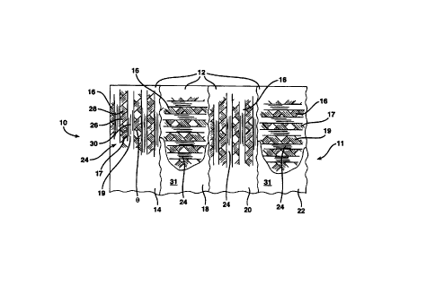
Referring to Fig. 1, one embodiment 11 of the panel 10 comprises a
plurality of laminae 12, four of which are shown in Fig. 1 for illustration
purposes. The
panel 11 includes a first lamina 14, a second lamina 18, a third lamina 20 and
a fourth
lamina 22. Each lamina 14, 18, 20 and 22 comprises a plurality of strands 16
which each
comprises a plurality of reinforcing fibers 17 and at least one polymeric
material 19. The
laminae 14, 18, 20, and 22 are joined together by fusing a portion of the
polymeric
material 19 of one lamina 12 with a portion of the polymeric material 19 of
another
-6-
CA 02271137 1999-OS-06
WO 98/46422 PCT/US98/00586
lamina 12. For example, polymeric material 19 from the strands 16 of the
lamina 14 fuses
with the polymeric material 19 from the strands 16 of the lamina 18; polymeric
material
19 from the strands 16 of the lamina 18 fuses with the polymeric material 19
from _the
strands 16 of the lamina 20; and polymeric material 19 from the strands 16 of
the lamina
20 fuses with the polymeric material 19 from the strands 16 of the lamina 22.
For any panel 10, the polymeric material 19 of the laminae 12 are
sufficiently melted and fused together to provide the panel 10 with the
mechanical
properties desired. The polymeric material 19 from each of the strands 16
forms all,
substantially all, or at least part, of the matrix for the reinforcing fibers
17 of each panel
10, according to the present invention. A11 of the matrix refers to the
polymeric material
19 from the strands 16 providing all of the matrix except for that formed by
any chemical
treatment that may have been applied to the reinforcing fibers 17 or any
fibers made of the
polymeric material 19. Substantially a11 of the matrix refers to the polymeric
material 19
from the strands 16 being enough to provide a matrix for all of the
reinforcing fibers 17 in
the panel 10. It does not preclude the use of additional matrix material from
a source
other than the strands 16.
In the exemplary panel 11, the various lamina 14, 18, 20 and 22 are
positioned angularly in relation to each other. The first lamina 14 is
arranged angularly to
the second lamina 18 which is arranged angularly to the third lamina 20. The
third lamina
20 is arranged angularly to the fourth lamina 22. By arranging the various
lamina in this
manner, the panel 11 is provided with reinforcement against loads applied
along both its
machine direction (i.e., length) and its cross machine direction (i.e.,
width). The strands
16 forming any lamina of a panel 11 can be positioned next to each other or
they can be
spaced apart. For some applications, a porous panel 11 is desirable. For
example, having
a porous panel 11 would allow air to flow through the panel 11 in order to
compensate for
air pressure differences on either side of the panel 11. For such an
application, the strands
16 in each lamina of a panel 11 can be sufficiently spaced apart to form
openings through
the panel 11. Laminae having strands spaced up to about 1 inch (2.54 cm) apart
have
been produced. It is believed that panels 11 with laminae having strands 16
spaced even
further apart can also be successfully produced.
_7_
CA 02271137 1999-OS-06
WO 98/46422 PCTNS98/00586
As shown in Fig. 1, each of the laminae 14, 18, 20 and 22 is in the form of
a reinforcement mat 24 which has a first layer 26 of the strands 16 and a
second layer 28
of the strands I6. The first and second layers 26 and 28 are positioned
relative to one
another so that their strands 16 of one layer 26 are at an angle 0 from the
strands 16 of the
other layer 28. It is desirable for the angle 8 to be in the range of from
about 6° to about
174°. It is more desirable for the angle 0 to be in the range of from
about 60° to about
120°. The first layer 26 of strands 16 is angularly positioned in
relation to the second
layer 28 of strands 16 so that each lamina 12 can more efficiently carry
loads.
During the formation process of mat 24, the first and second layers 26 and
28 are brought together and heated such that at least a portion of the
polymeric material
19 incorporated into the f rst and second layers 26 and 28 bond together so as
to join the
strands 16 of the first and second layers 26 and 28 to one another to form the
mat 24. In
other words, the polymeric material 19 of the layers 26 and 28 are
sufficiently fused
together to provide the lamina 12 with the mechanical properties desired. The
process for
forming such a mat 24 and a description of the mat 24 are set out in copending
United
States Patent Application Serial No. 08/713,319 (Attorney Docket No. 24084A)
entitled
"PROCESS AND APPARATUS FOR MAKING A REINFORCING MAT" and in
copending U.S. Patent Application Serial No. 08/7I3,318 (Attorney Docket No.
23689A)
entitled "A REINFORCEMENT MAT." Both of these applications are hereby
incorporated by reference in their entireties.
As an option, one or more of the mats 24 of the panel 1 I can further
include a third layer 30 of the strands 16. The strands 16 of the layer 30 run
lengthwise or
in the machine direction of the mat 24. The polymeric material 19 from the
layer 30 is
sufficiently fused with the polymeric material 19 from one or more of the
other layers 26
and 28. Each mat 24 may also include a layer or film 31 of polymeric material
sandwiched between and fused to any two of the layers 26, 28, and/or 30 to
serve as part
of the matrix for the reinforcing fibers 17.
As stated above, the laminae 12, which form the panel 11, or other of the
present panels 10, can be positioned in an angular relation to each other.
Particularly,
each of the laminae 12 can be positioned in an angular relation to the lamina
12 on one or
either side thereof. It is desirable for the angle between two adjacent
laminae 12 to be in
_g_
CA 02271137 1999-OS-06
WO 98146422 PCT/US98/00586
the range from about 30° and about 150°. It is more desirable
for the angle between
consecutive laminae 12 to be in the range of from about 60° and about
120°. It can be
even more desirable for the laminae 12 to be arranged approximately
perpendicular to
each other (i.e., at an angle of about 90°).
The panel 11 can be formed from two to sixteen of the laminae 12, such as
the reinforcement mats 24 described above, or possibly even more of the
laminae 12. It
can be desirable for the panel 11 to be formed from six to twelve, or even
from eight to
ten, of the laminae 12, such as the reinforcement mats 24 described above.
The panel 11, or other of the present panels 10, may be further reinforced
by means of additional reinforcing materials including those selected from the
group
consisting of glass fibers, graphite fibers, aramid fibers, silicon carbide
fibers and other
fibers having suitable reinforcing properties and combinations thereof. It can
be desirable
for these additional reinforcing materials to be formed into nonwoven or woven
mats 43
(see Figs. 2 and 3). By "nonwoven", it is meant that the reinforcing materials
in the mat
are not systematically woven together. One such reinforcing material is a
nonwoven glass
fiber mat, such as the continuous strand mats available from Owens Corning, of
Toledo,
Ohio, under the product designations M8608 and M8610. These types of mats are
made
of glass fibers laid in a continuous swirl pattern. Nonwoven glass fiber mats
can be
formed by air laying glass fibers into a mold and compressing the fibers
together in the
mold to form the mat. One nonwoven glass fiber mat 43 can be sandwiched
between one
or more pairs of adjacent laminae 12, the laminae 12 can be sandwiched between
a pair of
the nonwoven glass fiber mats 43 (see Figs. 2 and 3), or both.
The panel 11, or other of the panels 10, may also include a surface finish to
enhance the appearance and/or to further protect the panel. It is desirable
for the surface
finish to have good weatherability. Useful surface finishes include, for
example, plastic
films, ultraviolet protectants, water repellents, canvases (e.g., awning
material) and glass
mats such as those described above.
Referring to Fig. 2, another embodiment 41 of the panel 10 comprises
laminae 12 formed from strands 16 which are woven together by means of one or
more
threads 53 running at an angle (e.g., transversely) to the strands 16 to form
woven mats
54. The example of the panel 41 shown in Fig. 2 includes a first lamina 42, a
second
-9-
CA 02271137 1999-05-06
WO 98I46422 PCT/CJS98/00586
lamina 44, a third lamina 46, a fourth lamina 48 and a fifth lamina 50. Each
of the
laminae 44, 46, 48 and 50 comprises a plurality of strands 16 which each
comprise a
plurality of reinforcing fibers 17 and at least one polymeric material 19. The
laminae 44,
46, 48 and 50 are positioned between a pair of lamina 42 (one shown in Fig. 2)
which
each comprises additional reinforcing materials, such as that described above.
In the
embodiment shown, the additional reinforcing materials forming the lamina 42
are
nonwoven mats 43.
In the embodiment shown in Fig. 2, the first and second laminae 44 and 46
are arranged with their strands 16 parallel to each other and the third and
fourth laminae
48 and SO are arranged with their strands 16 parallel to each other. The first
and second
woven lamina 44 and 46 are arranged in an angular relation, here about
90°, to the third
and fourth woven lamina 48 and 50. The angular arrangement of the laminae 44,
46, 48
and 50, as shown or at any other angle, provides the panel 10 with
reinforcement in both
its machine direction and its cross machine direction, i.e., along both its
length and its
width.
In one modification of the panel 41, six laminae 12, formed from woven
mats such as mat 54, are arranged in pairs, with the strands i 6 in each pair
being oriented
in the same direction. A first pair of the woven mats 54 is sandwiched between
a second
pair and a third pair of the woven mats 54. The strands 16 of the first pair
of mats 54 are
positioned in an angular relation to the strands 16 of both the second and
third pairs of
mats 54. to form a laminated structure. This laminated structure is sandwiched
between a
pair of nonwoven fiber mats 43. The strands 16 of the panels 41 can be
woven together by means of a conventional weaving process known in the art to
weave
glass fibers into mats 54. Typically, the strands 16 are woven together by
threads 53
running transverse to the strands 16. These threads 53 can be made from any
suitable
thread fiber including those selected from the group consisting of glass
fibers, nylon
fibers, polyamide fibers, polypropylene fibers, polyester fibers, polyethylene
fibers, and
polyphenylene sulfide fibers. It can be desirable for the thread 53 to be
formed from the
same material as the polymeric material 19 used in the strands 16. Another
strand 16
could also be used for the thread 53.
-10-
CA 02271137 1999-OS-06
WO 98/46422 PCT/US98/00586
To maintain the strands 16 in position in the woven mat 54 and to prevent
fraying, the edges of the mat 54 can be stitched after the strands 16 have
been woven
together. The ends of the strands 16 can also be heated to at least partially
melt the_
polymeric material 19 and, thereby, prevent movement of individual fibers in
the strands
16. Such heating is particularly desirable with commingled strands 16.
The panel 41 can be formed from two to sixteen or even more laminae 12,
such as the woven mats 54, and additional reinforcing materials, such as
nonwoven fiber
mats 43. It is desirable for the panel 41 to be formed from four to twelve, or
even more,
of such laminae 12, depending on the diameter of the strands 16 and the
application for
which the panel 41 is being used.
Referring to Fig. 3, an alternative panel 41 comprises a first lamina 62
formed from an additional reinforcing material which, in the embodiment shown,
is a
nonwoven glass fiber mat 43; a second lamina 64 formed from a woven mat 54; a
third
lamina 66 formed from a woven mat 54; and a fourth lamina 68 formed from a
woven mat
54. The second lamina 64 is shown with its strands 16 oriented angularly, as
shown about
90°, in relation to the strands 16 of the third lamina 66. The strands
16 of the fourth
lamina 68 are shown as being positioned about parallel to the strands 16 of
the second
lamina 64 (i.e., about perpendicular to the strands 16 of the third lamina
66). However,
the laminae 62, 64, 66 and 68 can be oriented in any desired manner to
reinforce the
alternative panel 41. Again, by positioning the various woven laminae 64 and
66
angularly in relation to each other, the panel 41 is provided with
reinforcement against
loads applied along both its machine direction (i.e., length) and its cross
machine direction
(i.e., width).
In another modification of the panel 41, an additional reinforcing material,
such as a woven or nonwoven mat 43 made from aramid fibers, is positioned
between a
first lamina and a second lamina, both of which are formed from woven fiber
mats, such
as the mat 54. The first lamina is positioned with its strands 16 in an
angular relation to
those of the second woven lamina. A third lamina, formed from a woven fiber
mat, such
as the mat 54, is layered on the first lamina with its strands 16 in an
angular relation to
those of the first lamina. A fourth lamina, formed from a woven fiber mat,
such as the
mat 54, is layered on the second lamina with its strands 16 positioned in an
angular
-11-
CA 02271137 1999-OS-06
WO 98/46422 PCT/US98/00586
relation to the strands 16 of the second lamina to form a laminated structure.
This
laminated structure is sandwiched between two layers of additional reinforcing
materials,
such as the nonwoven fiber mats 43 described above.
The panel 10 can be formed by any suitable molding process such as, for
example, compression molding, transfer molding or injection molding. The
individual
laminae 12 can be formed by the process described in United States Patent
Application
Ser. No. 08/713,318, incorporated by reference above, by a conventional
weaving process,
or any other suitable process, depending upon which type of laminae 12 will be
used.
After the separate laminae 12 have been formed, they are positioned in a mold
cavity, for
example, of a compression molding, transfer molding or injection molding
apparatus.
During this time, the optional additional reinforcing materials, such as the
woven and/or
nonwoven fiber mats 43 and surface finishes, can be positioned in the mold.
The laminae
12 are then compressed, or pressure otherwise applied, to form a panel 10. As
the laminae
12 are being compressed, the mold is heated to cause portions of the polymeric
material
19 of the strands 16 from the separate lamina 12 to fully, or at least
partially, melt and
fuse or bond to each other and to bond to other polymeric material 19 in other
laminae 12.
After the panel 10 has been compressed to a desired thickness and density, it
is removed
from the mold and can be painted, coated with a protective coating and
processed further
if necessary. In addition, the final surface finish (e.g., a canvas) can be
incorporated as an
integral part of the panel 10 by including the surface finish in the molding
process.
Examples
Panels were formed according to the above described method and were
tested to determine their tensile stress, tensile modulus, flexural stress,
flexural modulus,
notched Izod and high rate impact strength. For comparison purposes, a glass
fiber mat
infiltrated with a thermoplastic material (GMT) was also tested. The panels
tested had the
following configurations:
Panel A - This panel was formed from 12 laminae. The individual lamina were
reinforcement mats formed by the process described in United States Patent
Application
Ser. No. 08/713,318, incorporated by reference above, using commingled glass
and
polypropylene fibers. First portions of the strands of each lamina were
arranged at a 90°
angle to second portions of the strands of each lamina to form a reinforcement
mat such as
-12-
CA 02271137 1999-OS-06
WO 98/46422 PCT/US98/00586
the mats 24 described above. The odd numbered lamina were positioned at a
90° angle to
even numbered lamina. In other words, alternating lamina were arranged at a
90° angle to
each of the other laminae.
Panel B - This panel had the same configuration as panel A with each side of
the panel
being covered with a layer of generic polypropylene film.
Panel C - This panel was formed using the laminae formed from woven mats such
as mat
54 described above. The woven mats were formed from strands comprising
commingled
glass reinforcing fibers and polypropylene fibers. In this panel, a first pair
of laminae was
positioned between a second pair of laminae and a third pair of laminae. The
strands in
I O laminae forming each pair were substantially parallel to each other. The
first pair of
laminae was positioned at a 90° angle to the second and third pair of
laminae. The entire
structure was then sandwiched between two nonwoven glass fiber mats.
Panel D - This panel was formed using laminae formed from woven mats, such as
mat 54
described above, comprising commingled glass-polypropylene fibers. In this
panel a
woven mat made of glass fibers, such as mat 54 described above, was positioned
between
first and second laminae formed from woven mats. The first and second laminae
were
positioned with their strands at a 90° angle to each other. The first
and second laminae
were then positioned between third and fourth lamina. The third lamina was
positioned
adjacent the first lamina at a 90° angle to the first lamina and at a
0° angle to the second
lamina. The fourth lamina was positioned adjacent the second lamina at a
90° angle to the
second lamina and at a 0° angle to the first lamina.
The above tests were performed according to the indicated ASTM testing
standards except for the "High Rate Impact" test which was performed on a
Rheometrics
Model RHIT-8000 High Rate Impact Tester. The test results were as follows:
PANEL A PANEL B PANEL C PANEL D
GMT MD/CD' MD/CD MD/CD MD/CD
Tensile Stressz 12.69 9.97 6.40 25.33 1 l.25
(103 psi) [MPa] [87.5] [68.7]/ [44.l]/ [174.6]/ [77.6]/
10.27 8.44 12.65 15.63
[70.8] [58.2] [87.2] [107.8]
-13-
CA 02271137 1999-OS-06
WO 98/46422 PCT/US98/00586
Tensile Modulus' 0.83 0.555 0.S28 l.096 0.853
(106 psi) [l03 MPa] [5.723] [3.827]/[3.640]/[7.557]/ [5.881]/
0.655 0.857 0.639 1.02
[4.5l6] [5.909] [4.406] [7.033]
.
Flexural Stress4 18.16 6.72 15.00 18.l7
6.59
(l03 psi) [MPa] [125.2] [45.4]/ [46.3]/ [103.4]/ [I25.3]/
8.27 8.70 6.72 10.13
[57.0] [60.0] [46.3] [69.8]
Flexural Modulus5 0.78 0.386 0.309 1.252 0.828
(106 psi) [103 MPa] [5.378] [2.66l]/[2.l30]/[8.632]/ [5.709]/
0.49l 0.364 0.269 0.507
[3.385] [2.510] [1.855) [3.496]
Notched Izodb 4.8 31.38/ 34.79/ 35.22/ 23.46/
(ft-lb) 26.b4 39.17 25.10 21.33
High Rate Impact 235 662 620 374 373
(in-lb)
Notes:
1 - Machine Direction/Cross Machine
Direction
2 - ASTM D 638
3 - ASTM D 638
4 - ASTM D 790
5 - ASTM D 790
6 - ASTM D 256
These tests demonstrate that these
panels have an improved strength
for
both impact resistance and puncture
resistance.
The panel 10 of this invention ake storm
can be used to m shutters
either
individually or by combining a The panels10 are
plurality of panels. also useful
to make
protective coverings for cash windowsinstitutions, coveringskiosks
of financial for and
carts in open areas of shopping s, aircraft
malls, side panels for tractor
trailers, boat hull
parts and other articles and partsresistance resistance
for which impact and/or
puncture
are desired.
-14-
CA 02271137 1999-05-06
WO 98/46422 PCT/US98/00586
Fig. 4 presents a perspective view of the panels of this invention being
combined to form a shutter or window covering 100. The shutter 100 comprises a
series
of panels l02 each having interlocking lips 104 as shown in Fig. 4A. The
panels 102
remain hidden behind a shutter facade 106 until they are needed to protect the
window
108. To move the panels 102 into position to protect window 108, the panels
are pulled
from behind facade 10b and slid along a track 110. As they are pulled, their
lips 104
interlock to pull successive panels from behind facade l06. The interlocking
lips 104 also
help to prevent penetration of airborne debris and precipitation through
shutter 100 to
window 108.
Fig. 5 presents a perspective view of the panels of this invention being
combined to form another shutter 200. The shutter 200 comprises a plurality of
panels
202, each having a first lip 204 and a second lip 206, as shown in Fig. SA.
The panels
202 are stored in a box 208 under the window 210. The panels 202 are moved
into
position to protect window 210 by means of an interiorly or exteriorly mounted
crank or
pull cord. The first lip 204 of the first panel 212 is mounted on a slide bar
214 which
pulls the panels 202 into position. As the panels 202 are raised, the second
lip 206 on one
panel engages the first lip 204 on the panel beneath it to raise that panels
to cover the
window 2l0. Again, the interlocking nature of the panels 202 helps to protect
the window
210 from the penetration of airborne debris and precipitation through shutter
200 to
window 210.
Fig. 6 presents a perspective view of the panels of this invention being
employed as another type of window covering. In this embodiment, a series of
panels 300
are separately mounted to protect a window 302. The panels 300 each include
interlocking lips or edges (not shown) to help prevent the penetration of
airborne debris
and precipitation to the window 302. The upper portion of each panel 300
includes an
edge portion 304 which engages a bracket 306 mounted over the top of the
window 302,
as shown in Fig. 6A. Bracket 306 may also include a rubber gasket 308 to
further prevent
the penetration of water through panel 300 to window 302. Fig. 6B presents a
cross
sectional view of one of the panels 300. Each panel 300 includes a latch
mechanism 310
which is used to attach the panel 300 to a mount 312 on a wall 314 surrounding
the
window 302. Thus, each panel 300 is secured in position over the window 302 by
means
-15-
' CA 02271137 1999-OS-06
WO 98/46422 PCT/US98/00586
of the engagement of edge portion 304 with bracket 306 and the engagement of
latch
mechanism 310 with mount 312 on wall 314.
Fig. 7 presents a perspective view of the panels of this invention being
used to form an alternate shutter 350 which simulates roofing tile. The
shutter 350
comprises a series of panels 352 which are rotatably mounted over a window
354. Each
panel 352 includes lips 356, shown in Fig. 7A, which engage each other to
prevent the
separate panels 3 52 from being extended past the point of engagement of each
panel and
to help prevent the penetration of precipitation and wind borne debris from
contacting the
window 354.
Fig. 8 presents a perspective view of the panels of this invention being
used to form another alternate shutter 400 which simulates roofing tile. In
this
embodiment, the shutter 400 includes a facade section 402, a first section 404
and a
second section 406. Rather than sliding into position to cover a window 408,
the shutter
400 is hinged so that first section 404 and second section 406 unfold from
beneath facade
section 402 to cover window 408. Second section 406 can be held in a closed
position by
securing clips 412 which can be rotatably mounted beneath window 408. When
folded
into a position at which it is not covering window 408, shutter 400 includes
an arm 410
which can be used to brace shutter 400 in an open position.
While certain representative embodiments and details have been shown for
the purpose of illustrating the invention, it will be apparent to those
skilled in the art that
various changes in the product and method described herein may be made without
departing from the scope of the invention, which is defined in the appended
claims.
- I 6-