Note: Descriptions are shown in the official language in which they were submitted.
CA 02271409 1999-OS-10
PATENT
ATTORNEY DOCKET NO.: SCH-26
UTILITY METER INTERFACE UNIT
Background of the Invention
The present invention relates to automatic and
remote meter reading systems of the type used in the
utility industry. In particular, the invention
relates to radio frequency ("RF") systems used to
communicate with metering devices so that utility
consumption can be determined from a remote location.
As is well known, utility industries (such as
gas, electricity and water) typically install a meter
to indicate consumption by a particular customer. The
consumption indicated by the meter forms the basis of
the bill sent to the customer each month (or over
another predetermined period of time). To read
consumption from the meter, the utility industries
have often utilized personnel whose job has been to
physically inspect meters at each customer location.
In order to reduce the need for meter-reading
personnel to inspect every meter, many utilities have
begun using various automatic meter reading ("AMR")
and remote meter reading ("RMR") systems. These
systems simplify the meter-reading process, by reading
usage information from the individual meters through
RF transmission. Toward this end, each of the meters
will include a meter interface unit ("MIU") that
controls transmission of usage information read from
the meter. At a predetermined scheduled time or upon
receipt of an electronic request, the MIU will send
CA 02271409 1999-OS-10
2
the usage information via a predetermined RF format.
Examples of MIU devices of the prior art are shown,
for example, in U.S. Patent Nos. 5,553,094 and
4,839,642. Each of these patents is incorporated
herein by reference.
In the past, it has often been necessary to
provide a dedicated MIU device for the particular
meter encoder with which it will be utilized. For
example, water meters may be equipped with one of a
.number of different types of meter encoders. In
addition, a particular usage location may contain
several meter encoders networked together to provide
compound, or multiple, registers. Thus, it was often
necessary to determine which of any number of MIU
devices was required in a particular application.
In addition, certain older meter encoders have
been considered to be generally incompatible with
newer electronics technology. For example, older
meter encoders often require voltage levels of 5 volts
or greater in order to read usage information. In
contrast, modern integrated circuits operate
effectively at lower voltage levels, typically 3.6
volts or less. In addition, to limit the need for
battery replacement, it is desirable to conserve
battery power whenever possible.
Summary of the Invention
The present invention recognizes various
disadvantages of prior art constructions and methods.
Accordingly, it is an object of the present invention
CA 02271409 1999-OS-10
3
to provide novel arrangements for the construction of
a utility meter interface unit.
It is a further object of the present invention
to provide a meter interface unit that can be used
with a variety of meter encoder types.
It is a further object of the present invention
to provide a meter interface unit operating at a lower
voltage level than the meter encoder, while employing
a lower voltage power source.
. It is a further object of the present invention
to provide a meter interface unit which effectively
conserves power during times when usage information is
not being determined.
It is a further object of the present invention
to provide a meter interface unit which can supply a
selected clock signal depending on the type of
encoder.
Some of these objects are achieved by a utility
meter interface unit for use with a meter encoder.
The unit comprises a transmitter operative to send
usage information obtained from the meter encoder to a
remote location. A processor is operative to initiate
reading of usage information from the meter encoder
and to control transmission thereof. Power management
circuitry responsive to the processor is also
provided. The power management circuitry is operative
to direct power from a power source to the meter
encoder only at selected times such that power is
conserved during periods when the usage information is
CA 02271409 1999-OS-10
4
not being read.
In some exemplary embodiments, voltage from the
power source is modulated by the power management
circuitry and supplied to the meter encoder at a
S predetermined frequency. Preferably, the processor
may be operative to identify the meter encoder and
responsively adjust the predetermined frequency based
thereon. For example, the processor may be operative
to read the usage information from both single and
1~0 .compound register encoders.
In addition, the device may read usage
information from networks of multiple meter encoders.
In such applications, multiple encoders may read using
a multiplicity of data lines while employing a common
15 clock signal.
Often, the power management circuitry will
include step-up circuitry operative to step-up a
source voltage supplied by the power source to a
predetermined higher voltage level. In some exemplary
20 embodiments, the step-up circuitry may include a
storage capacitor for maintaining the predetermined
higher voltage level. A selectively conducting
arrangement, such as at least one transistor, may be
connected in circuit with the storage capacitor. In
25 such embodiments, the selectively conducting
arrangement is controlled to switch at the
predetermined frequency. Often, it will be desirable
for the step-up circuitry to include an inductor
connected in circuit with a diode to supply charging
CA 02271409 1999-OS-10
current to the storage capacitor.
Other objects of the present invention are
achieved by a utility meter interface unit for use
with a meter encoder which comprises a transmitter
5 operative to send usage information obtained from the
meter encoder to a remote location. A processor is
operative to initiate reading of the usage information
from the meter encoder and store data representative
thereof in a memory. The processor is further
.operative during reading of the usage information to
identify the meter encoder from among at least two
known encoder types. The processor is also operative
to control transmission of the usage information
utilizing a predetermined transmission protocol.
In some exemplary embodiments, the processor is
operative to effect a different clock frequency to be
supplied to the meter encoder depending on which type
of known encoder is identified. For example, a first
of the known encoder types may be a single register
encoder and a second of the known encoder types may be
a compound register encoder. Depending on the type,
the predetermined frequency may be either
approximately 1200 hertz or approximately 19.2
kilohertz in some exemplary embodiments.
Often, the meter interface unit may comprise a
battery and power management circuitry responsive to
the processor. In such embodiments, the power
management circuitry is operative to direct power from
the battery to the meter encoder only at selected
CA 02271409 1999-OS-10
6
times such that battery power is conserved during
periods when the usage information is not being read.
Often, the power management circuitry will be
operative to modulate voltage from the battery and
supply the modulated voltage to the meter encoder at
the predetermined frequency. In addition, the power
management circuitry may include step-up circuitry
operative to step-up a battery voltage supplied by the
battery to a predetermined higher voltage level.
. Still further objects of the present invention
are achieved by a meter interface unit for use with a
meter encoder requiring a predetermined encoder
voltage level. The unit comprises a power source
supplying a source voltage level less than the encoder
voltage level. A transmitter is operative to send
usage information obtained from the meter encoder to a
remote location. A processor is also provided,
operative to initiate reading of the usage information
from the meter encoder and to control transmission
thereof. Power management circuitry responsive to the
processor is also provided. The power management
circuitry includes step-up circuitry operative to
step-up the voltage level supplied by the power source
to at least the encoder voltage level.
Additional objects of the present invention are
achieved by a method of reading usage information from
a utility meter encoder. One step of the method
involves supplying power to the encoder at a first
predetermined frequency. Based on information
CA 02271409 1999-OS-10
7
responsively supplied by the encoder, it is verified
whether the encoder is of a first known type. If the
encoder is not of the first known type, power is
supplied to the encoder at a second predetermined
frequency. Based on information responsively supplied
by the encoder, it is then verified whether the
encoder is of a second known type. Usage information
from the encoder is read and appropriately stored.
The usage information is then transmitted to a remote
.location for further use as necessary.
Often, the first known type of encoder may be a
single register encoder, and the second known type of
encoder may be a multiple register encoder. When the
encoder is of the second known type, usage information
from each of the multiple registers may be
successively read and stored. According to exemplary
methodology, the first predetermined frequency may be
approximately 1200 hertz and the second predetermined
frequency may be approximately 19.2 kilohertz. Often,
it will be desirable to convert usage information
received from the meter encoder in a first format to a
second format prior to transmission thereof.
Other objects, features and aspects of the
present invention are provided by various combinations
and subcombinations of the disclosed elements, as well
as methods of practicing same, which are discussed in
greater detail below.
Brief Description of the DrawincLs
A full and enabling disclosure of the present
CA 02271409 1999-OS-10
8
invention, including the best mode thereof, to one of
ordinary skill in the art, is set forth more
particularly in the remainder of the specification,
including reference to the accompanying drawings, in
which:
Figure 1 is a diagrammatic representation of a
meter interface unit ("MIU") constructed in accordance
with the present invention;
Figure 2 is a schematic diagram of power
.management circuitry in accordance with a preferred
embodiment of the present invention;
Figures 3A, 3B and 3C are respective waveforms
showing operation of the step-up and modulated
switching circuitry included within the power
management circuitry of Figure 2;
Figure 4 is a diagrammatic representation of an
encoder system having compound registers, with which
the MIU of Figure 1 may be utilized; and
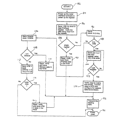
Figure 5 is a flow chart showing operation of the
processor to determine the type of meter encoder and
thereafter read usage information therefrom.
Repeat use of reference characters in the present
specification and drawings is intended to represent
same or analogous features or elements of the
invention.
Detailed Description of Preferred Embodiments
It is to be understood by one of skill in the art
that the present discussion is a description of
exemplary embodiments only, and is not intended as
CA 02271409 1999-OS-10
9
limiting the broader aspects of the present invention,
which broader aspects are embodied in the exemplary
constructions.
Figure 1 illustrates a meter interface unit (MIU)
S 10 of the present invention utilized in conjunction
with a meter encoder 12. Typically, meter encoder 12
will function to read usage information from a
metering apparatus, such as a mechanical flowmeter.
As an example, a water flowmeter will generally have
mechanical wheels on which water consumption is
displayed. Meter encoder 12 functions to convert the
mechanical display into electronic information which
is then stored in a local register.
Depending on the type, meter encoder 12 may have
one register or multiple registers for temporarily
storing usage information. For example, a water meter
having a single flowmeter apparatus may be equipped
with a single register. Certain meters, such as those
including devices for measuring both high and low
levels of flow, may be equipped with multiple storage
registers. In the past, it has generally been
necessary to provide a unique MIU depending on the
specific type of meter encoder being used in a
particular situation.
As will be described more fully below, MIU 10 is
capable of recognizing which type of meter encoder
with which it is being used, and to vary its operating
characteristics accordingly. As such, MIU 10
overcomes the need frequently seen in the prior art to
CA 02271409 1999-OS-10
provide a unique MIU for each meter encoder.
Like the prior art, MIU 10 functions to transmit
usage information obtained from meter encoder 12 to a
remote location for further processing. Because the
5 illustrated embodiment utilizes RF transmission, MIU
10 is equipped with an antenna 14 and a suitable
transmitter 16. Other embodiments, however, may
utilize telephone or transmission of another type to
send the usage information. Typically, MIU 10 may
10 initiate reading of usage information from meter
encoder 12 on a scheduled basis. Preferably, the
scheduled time at which reading occurs may be
programmable.
As can be seen, MIU 10 includes a microcontroller
18 which is operative to control transmission of usage
information obtained from meter encoder 12.
Microcontroller 18 includes a processor 20 that
implements firmware instructions stored in a suitable
non-volatile memory, such as read-only memory (ROM)
22. A random access memory (RAM) 24 may also be
provided to permit temporary storage of usage
information and the like. MIU 10 further includes
power management circuitry 26 functionally interposing
microcontroller 18 and meter encoder 12 as shown.
Often, MIU 10 will be located remote from a
source of constant electricity. In this case, MIU 10
is equipped with a battery functional to supply a
predetermined battery voltage level, UHAT~ Preferably,
the integrated circuits and other components of MIU 10
CA 02271409 1999-OS-10
11
are fabricated according to newer technology to
effectively operate at relatively low voltage levels.
For example, modern integrated circuits can often
operate effectively at voltage levels of less than 3.6
volts. A battery comprising three cells of 1.2 volts
each may thus be used for this purpose.
Unlike the components of MIU 10, many meter
encoders are designed to operate at higher voltage
levels. For example, it is not unusual for meter
encoders to require voltage levels of 5 volts or more
in order to accurately read and store usage
information. Thus, power management circuitry 26 is
configured to step-up the voltage level VeAT to the
higher voltage level needed by encoder 12. In
addition, power management circuitry 26 is operative
to supply power to meter encoder 12 only at selected
times when usage information needs to be obtained. As
such, battery life is greatly extended over what would
be the case if power were supplied to meter encoder 12
at all times. In addition, power management circuitry
26 functions to provide power to meter encoder 12 at a
predetermined frequency which may be varied under the
control of microprocessor 20 depending on the type of
meter encoder.
Figure 2 illustrates a schematic of power
management circuitry 26 in one preferred
implementation. As can be seen, circuitry 26 is
connected to processor 20 through three lines
collectively indicated at 30. The three lines are
CA 02271409 1999-OS-10
12
respectively labeled "ENABLE," "CLOCK1" and "READ."
Likewise, power management circuitry 26 is connected
to meter encoder 12 through three lines collectively
indicated at 32. As can be seen, these three lines
are respectively labeled "CLOCK2," "GND" and "DATA."
The ENABLE input from processor 20 instructs
power management circuitry 26 to allow power to be
supplied to meter encoder 12. In this case, the
ENABLE signal is a "low" signal which causes
transistor 34 to conduct. As a result, a voltage
USWITCH will be produced at the collector of transistor
34. It will be appreciated that the voltage VSWrTCx is
the voltage V~,,T reduced by the voltage drop across
transistor 34. (The resistance value of resistor 36
will be small in relation to that of resistor 38.)
When the ENABLE input is high, transistor 34 will be
maintained in a non-conducting state by the voltage
supplied to its base through resistors 40 and 42.
The voltage VSWITCH activates step-up circuitry 44
which supplies the higher voltage level necessary to
operate meter encoder 12. Toward this end, step-up
circuitry 44 includes an integrated circuit (IC) 46
which receives the voltage VSWITCx as a power input at
its pin 1. When power is received, IC 46 operates to
supply a DC output from pin 2. A high frequency
output (shown in Figure 3A) having a peak voltage
level VSWIT~ is supplied from pin 5. Preferably, the
frequency of the pin 5 output will be many times the
clock frequency used to read usage information from
CA 02271409 1999-OS-10
13
the meter encoder. For example, the output of pin 5
may have a frequency of approximately 300 kilohertz or
greater. A suitable integrated circuit for use as IC
46 is available under Part No. ISC8321 from Vishay.
It can be seen that the DC output from pin 2 of
IC 46 is applied to one terminal of a capacitor 48.
As a result, capacitor 48 will be charged up to at
least this voltage level. In addition, the output of
pin 5 is applied to a terminal interconnecting a diode
'S0 and an inductor 52. Inductor 52 is, in turn,
connected to voltage VHAT. In presently preferred
embodiments, a pulse width modulated (PWM) signal is
supplied as an output from pin S of IC 46. It should
be appreciated, however, that other suitable output
signals, such as frequency modulated or pulse
frequency modulated signals, may also be supplied.
As a result of the pulse applied from pin 5 of IC
46, a charging current will be produced in inductor
52. When the pulse is off, this current flows through
diode 50, increasing the charge across capacitor 48.
The resulting voltage of 5 volts or more that appears
on capacitor 48 (shown in Figure 3B) is produced from
charging current passing through diode 50. Diode 50
will prevent backfeed of current through inductor 52.
Meter encoders are typically configured to
receive operational power as a pulse width input
having a predetermined frequency and duty cycle. For
example, many meter encoders are configured to operate
at a frequency of 1200 hertz and 50°s duty cycle.
CA 02271409 1999-OS-10
14
Other meter encoders, such as those having multiple
registers, are often designed to operate at higher
frequencies. For example, some encoders having
compound registers are designed to operate from a 19.2
kilohertz input signal of 50% duty cycle. In addition
to supplying power to the meter encoder, the square
wave input provides a clock signal against which
output of the encoder's register is synchronized.
As will be described more fully below, processor
~20 is operative to identify meter encoder 12 from
among several known types. Depending on the type of
meter encoder that is identified, the clock frequency
that is output by microprocessor 20 may be varied
accordingly. This clock signal is received by power
management circuitry 26 along the CLOCKl input. The
clock signal is then applied to switching circuitry 54
which modulates the voltage across capacitor 48.
Figure 3C illustrates the modulated output of
switching circuitry 54. In this case, switching
circuitry 54 is "chopping" the DC voltage on capacitor
48 at a frequency of 19.2 kHz. Because 19.2 kHz is
about 15.63 times lower in frequency than the 300 kHz
output from pin 5 of IC 46, the time scale in Figure
3C has been compressed by a like amount. Otherwise,
each pulse in Figure 3C would extend beyond the period
shown in Figures 3A and 3B.
Switching circuitry 54 includes a pair of field
effect transistors (FETs) 56 and 58 arranged in series
as shown. A biasing resistor 60 is connected across
CA 02271409 1999-OS-10
FETs 56 and 58 to limit current flowing through FET
58. Through the operation of switching circuitry 54,
power is applied to the clock output of power
management circuitry 26 at the desired voltage and
5 frequency for reading usage information from meter
encoder 12. As shown, a resistor 62 is provided to
limit current flowing into meter encoder 12. A
resistor 64 is provided to "pull down" the CLOCK2
input of meter encoder 12 when power is not being
10 .applied.
Usage information is read from meter encoder 12
at its DATA output. The information is detected by
processor 20 along the READ line of power management
circuitry 26. A pair of grounded capacitors 68 and 70
15 are connected on respective sides of diode 66 to
filter noise that may be present in the data signal.
This is particularly advantageous in view of the
relatively long distance that may separate MIU 10 and
meter encoder 12. Often, even if a higher frequency
signal (e. g., 19.2 kHz) is used to power the meter
encoder, the data will still be read out at a lower
f requency ( a . g . , 12 0 0 Hz ) .
Voltage level VSWZTCx is applied to the READ line
through a resistor 72 for reducing the voltage of the
data fed from meter encoder 12 to the lower voltage
level at which components of MIU 10 operate. A common
ground, as indicated by the GND line extending between
power management circuitry 26 and meter encoder 12,
provides a common ground level for reference purposes.
CA 02271409 1999-OS-10
16
Referring to Figure 4, certain additional aspects
of meter encoder 12 will be explained. In this case,
meter encoder 12 includes a pair of reader circuits 74
and 76 associated with a respective mechanical
consumption meter. For example, the meter associated
with circuit 74 may indicate consumption of water at
low levels of flow. The meter associated with circuit
76 may be configured to indicate consumption of water
at higher flow levels. Each of the meters will
typically include mechanical wheels which are read,
and converted to electronic data. The electronic
data, in turn, is stored in respective registers 78
and 80.
As shown, the CLOCK2, GND and DATA lines extend
to register 78, which has three like lines extending
to register 80. Power is fed to meter encoder 12 by
the CLOCK2 output of power management circuitry 26.
The frequency of the clock signal is utilized as a
basis for synchronizing the output of electronic
information along the DATA line. The power signal
passes is also used to charge a capacitor inside of
register 78. The frequency and duty cycle of the
clock signal is chosen so that the capacitor will stay
charged sufficiently to allow data to be read from the
encoder.
As stated above, MIU 10 includes appropriate
firmware permitting it to recognize meter encoder 12
from several possible alternatives. Figure 5
illustrates exemplary method steps that may be
CA 02271409 1999-OS-10
17
implemented by processor 20 to perform this function.
As shown, block 82 represents the start of the
program. Once processor 20 is powered up, the program
starts executing from the beginning. The program then
moves to the next function, indicated by block 84. At
this point, initialization and power up configuration
tasks are performed. The program initializes the I/O
ports, timers and registers of processor 20 to the
correct stage. At the end of the initialization, the
.program starts the main loop to read, verify and
transmit the usage information via RF protocol.
At block 86, an ENABLE signal is sent to power
management circuitry 26. Processor 20 configures
itself to accept data from the encoder register. A
predetermined clock of a first frequency, such as 1200
hertz, is begun to cause reading a first type of
encoder. For example, a 1200 hertz clock can be
initiated to read data from a "ProRead" encoder
marketed by Schlumberger RMS. Next, the program moves
to decision block 88, where it verifies that the data
being received from the meter encoder is of the
ProRead type. If the data is of the ProRead type, the
program moves to block 90. At block 90, the data is
verified for undesirable opens ("-") or shorts ("H").
The term "open" means that there is no electrical
contact with one or more of the mechanical wheels in
the consumption meter. The term "short" means that
two digits are being shorted together to give an
invalid reading.
CA 02271409 1999-OS-10
18
Once the data is verified for opens and shorts,
it is saved in RAM 24. Often, this function will
convert the data to a BCD format, where it is saved in
the RAM buffer. The converted data is then saved in a
predefined transmit buffer for transmission. At 92,
processor 20 causes the transmit function to transmit
the data with the correct ID and account number.
After the data has been transmitted, the
microprocessor is again powered down, as indicated at
~ 94 .
Referring again to block 88, the program moves to
block 90 if the data does not identify the first
expected type of meter encoder. Processor 20 may then
send power of a second predetermined frequency to
meter encoder 12. For example, to check for compound
registers of the ProRead type, a 19.2 kilohertz signal
may be sent. As indicated at decision block 98, the
program determines whether any data is being received
from meter encoder 12. For example, the program may
wait at least 300 milliseconds for ProRead network
data. If the data starts coming within 300
milliseconds, then the program may move to block 100.
If the program is at the stage indicated by block
100, it looks for the network number. Usage
information from each available register will be
pulled and saved until all of the registers are read,
as indicated at decision block 102.
After the last register has been read, the
program moves to block 104. This function verifies
CA 02271409 1999-OS-10
19
the data for opens and shorts, and adjusts the
transmit interval time in ROM 22 to transmit the
network data one register data at a time at a shorter
interval time with proper ID and account numbers.
This function converts the data to a HCD format. A
number is loaded in the flag byte which indicates the
number of registers' data that needs to be transmitted
from the last read. The main module is forced to
retrieve the data from ROM 22 for transmission with a
.shorter interval, which will preferably be the same
for each register. At this point, the program
proceeds to block 92 for transmission and block 94 for
power down as described above.
If no data is sensed at decision block 98, the
program moves to block 106. The program will now
check to determine whether meter encoder 12 is of
another known type. For example, a 1200 hertz clock
signal may be sent to meter encoder 12 to determine
whether a Sensus meter encoder is present. At
decision block 108, the program verifies whether the
data received from meter encoder 12 appears to be of
the Sensus type. If so, the program moves to block
110. At block 110, the data is converted to a BCD
format and placed in the transmit buffer for
transmission at block 92.
If the data is not of the Sensus type, the
program moves to block 112 where it begins checking
for another known type of meter encoder. For example,
the program may send a 1200 hertz clock to meter
CA 02271409 1999-OS-10
encoder 12 to determine whether a ARB V encoder is
present. The data is read twice from the ARB V
encoder so that the two readings can be compared
(since there is no checksum in this case). At
5 decision block 114, the program determines whether
valid data is being received. If data is present in
the "DATA" line, then the program moves to block 116.
At this point, the program checks for opens and
shorts, and converts the data to a BCD format. The
10 .converted data is then placed in the transmit buffer
for transmission, as indicated at block 92.
If no data is detected at decision block 114, the
program moves to block 94 for power down. At this
point, MIU 10 waits for the next scheduled read to
15 occur.
It can be seen that the present invention
provides a novel meter interface unit in furtherance
of the noted objects. While various constructions are
described above, one skilled in the art will
20 appreciate that variations and modifications may be
made without departing from the invention. In
addition, aspects of the various embodiments may also
be interchanged both in whole or in part.
Furthermore, those of ordinary skill in the art will
appreciate that the foregoing description is by way of
example only, and is not intended to be limitative of
the invention so further described in such appended
claims.