Note: Descriptions are shown in the official language in which they were submitted.
CA 02271491 1999-OS-10
STACKABLE, FOLDABLE FOOD CONTAINER
FIELD OF THE INVENTION
This invention relates to an improved food container
assembled from a foldable blank and designed specifically
for transport of a food product such as pizza or other
food items.
BACKGROUND OF THE INVENTION
Many food containers are known which are
preassembled and preglued to a defined three-dimensional
shape. Such containers, however, are bulky for both
shipment and storage, and thus are not desired in many
use applications, such as for carry-out pizza.
Various types of foldable blanks are also known
which are used to create a box or other suitable support
for packaging and carrying food products such as pizza.
Prepared ready-to-eat pizza and other food items for
take-out or delivery are often packaged in a square box
formed from such a foldable blank, which boxes typically
have an attached openable lid or cover. Use of flat
blanks which are easily assembled without glue or
adhesive, which can be easily and compactly stored, and
which can be easily assembled at the use site, is thus
highly preferred in many use situations.
Many take-out or pizza establishments pre-fold or
set up food boxes prior to usage in order to save time
during busy periods. As a result, a typical pizzeria can
have a large number of set up boxes within the store,
which consumes considerable storage space. As such,
boxes which are capable of being nested one within the
other and stacked are known, such as those disclosed in
U.S. Patent Nos. 1 725 524 and 5 713 509. For- example,
the box illustrated in U.S. Patent No. 1 725 524 has side
walls which, when assembled, have a tapered configuration
for permitting vertical stacking of the boxes within one
another. These known arrangements, however, either do
1
CA 02271491 1999-OS-10
not possess a structure which provides the necessary
rigidity and structural integrity when assembled and
subsequently transported and/or possess a structure more
complex and hence more expensive than desired.
More specifically, many food containers which are
formed and folded from flat blanks utilize blanks which
are of thin paperboard and thus are quite flexible, and
hence can be partially prefolded and still partially nest
when stacked due to the flexibility of the board. These
containers, however, are relatively weak, possess less
than desired rigidity, and do not possess desired thermal
or moisture absorbing properties for optimum use with hot
food products. Because of these disadvantages, many food
containers and particularly pizza boxes are formed and
folded from flat blanks of corrugated cardboard,
typically double faced corrugated cardboard, because of
the strength, rigidity and other desired physical
properties thereof. The stiffness of these corrugated
blanks, however, has prevented most such containers from
being nested in an assembled condition, thereby requiring
a large storage space for the preassembled containers.
Accordingly, it is an object of the invention to
provide an improved food container for supporting a food
product such as pizza, which food container is formed by
being folded from a corrugated cardboard flat blank and
when partially folded or assembled is capable of being
nested so as to conserve space during storage thereof,
and which container is stable and has improved rigidity
to allow for safe handling and transport of the food
product therein.
More specifically, the improved food container, in
accordance with one aspect of the invention, includes
upper and lower portions joined to one another such that
the upper portion is pivotable away from and toward the
lower portion to respectively define open and closed
configurations of the container. The lower portion
2
CA 02271491 1999-OS-10
includes a generally horizontally enlarged and planar
bottom wall having a pair of generally parallel first
side edges and a pair of second side edges extending
generally perpendicularly relative to the first side
edges. First and second elongate side walls are
integrally joined to the bottom wall and fold upwardly
about the first side edges, and angle outwardly relative
to the bottom wall. A front flap extends outwardly from
a front end of each side wall, and a rear flap extends
outwardly from a rear end of each side wall. Each front
and rear flap is folded about respective front and rear
fold lines which form an angle greater than 90° relative
to a corresponding one of the first side edges to define
front and rear corners of the bottom portion. A rear
slot is disposed adjacent each rear corner, and a front
slot is disposed adjacent each front corner. The lower
portion includes front and rear side walls which are
integrally joined to the bottom wall and fold upwardly
about the second side edges. The front and rear side
walls are angled outwardly relative to the bottom wall.
The upper portion includes a generally planar top wall
having a pair of generally parallel first side edges and
a pair of generally parallel second side edges extending
generally perpendicularly relative to the first top wall
side edges. Upper portion also includes first and second
elongate side walls integrally joined to the top wall and
folded therefrom about fold lines which extend along the
top wall first side edges. Each first and second top
wall side wall has a locking tab which extends outwardly
from an end thereof adjacent the rear side wall, each for
engagement within a corresponding one of the rear slots
in the closed configuration of the container. The top
wall is integrally joined to the rear side wall and
pivotable with respect thereto. Upper portion further
includes a third elongate side wall integrally joined to
the top wall and folded therefrom about a fold line which
3
CA 02271491 1999-OS-10
extends along the other of the top wall second side
edges. The third side wall has a pair of locking tabs
extending outwardly from opposite ends thereof, each for
engagement within a corresponding one of the front slots.
Another aspect of the invention resides in a food
container having upper and lower portions whereby the
lower portion includes a planar bottom wall having a pair
of generally parallel first side edges and a pair of
generally parallel second side edges extending generally
perpendicular relative to the first side edges, and first
and second elongate side walls integrally joined to the
bottom wall and folded upwardly therefrom about fold
lines which extend along the first side edges. The lower
portion also includes front and rear side walls
integrally joined to the bottom wall and folded upwardly
therefrom about fold lines which extend along a
respective one of the second side edges. The first and
second side walls and also the front and rear side walls
are oriented at an interior angle greater than 90° with
respect to the bottom wall to enable vertical stacking of
a plurality of assembled but open containers one atop the
other. Further, opposite ends of the rear side wall,
along with adjacent rear ends of each of the first and
second side walls form a pair of rear corners of the
container, and opposite ends of the front side wall along
with adjacent front ends of the first and second side
walls form a pair of front corners of the container.
The lower portion additionally includes a pair of
upwardly opening slots, each disposed adjacent a
respective one of the front corners. The upper portion
of the container includes a generally planar top wall
having a first pair of parallel side edges and a second
pair of generally parallel side edges extending generally
perpendicularly relative to the first pair of top wall
side edges. The top wall is integrally joined to the
rear side wall about a fold line which extends along one
4
CA 02271491 1999-OS-10
of the first top wall side edges, and an elongate side
wall is integrally joined to the top wall and folded
therefrom about a fold line which extends along the other
of the first top wall side edges. The top wall side wall
has a pair of locking tabs extending outwardly from
opposite ends thereof each for engagement within one of
the slots in the closed configuration of the container.
Other objects and purposes of the invention will be
apparent to persons familiar with arrangements of this
general type upon reading the following specification and
inspecting the accompanying drawings.
BRIEF DESCRIPTION OF THE DRAVrINGS
Figure 1 is a plan view of an unfolded flat blank
according to the present invention;
Figure 2 is an overhead perspective view of an
assembled container formed from the blank of Figure 1 in
an open configuration.
Figure 3 shows a plurality of open, assembled
containers in a nested or vertically stacked
configuration;
Figure 4 is an overhead perspective view of the
container in a closed configuration;
Figure 5 is a right side view of the closed
container;
Figure 6 is a front view of the closed container;
Figure 7 is a rear view of the closed container;
Figure 8 is a fragmentary view similar to Figure 5;
Figure 9 is a fragmentary view similar to Figure 6;
and
Figure 10 is an enlarged, fragmentary bottom view of
the container.
Certain terminology will be used in the following
description for convenience in reference only, and will
not be limiting. For example, the words "upwardly",
"downwardly", "rightwardly" and "leftwardly" will refer
to directions in the drawings to which reference is made.
5
CA 02271491 1999-OS-10
The words "inwardly" and "outwardly" will refer to
directions toward and away from, respectively, the
geometric center of the container or blank and designated
parts thereof. Said terminology will include the words
specifically mentioned, derivatives thereof, and words of
similar import.
DETAILED DESCRIPTION
Referring to Figure 1, the present invention is
directed to a flat blank 10 preferably constructed from
stiff double-sided corrugated cardboard having a
corrugated interior layer bonded between a pair of flat
facing layers, which layers are all of rather thin paper.
However, the blank 10 may also be constructed of single-
sided corrugated cardboard having a corrugated layer
bonded to a single flat facing layer, with the corrugated
layer facing inwardly toward the food product. The blank
10 is prepared using techniques which are conventional
and well known in the box forming industry.
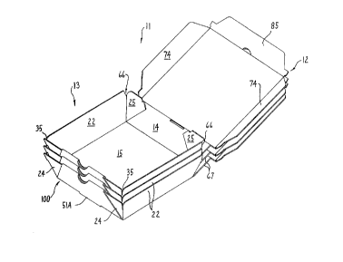
The blank 10 is foldable into the shape of a box or
container 11 (Figure 4) suitable for carrying a food
product, such as pizza. The container 11 includes upper
and lower portions 12 and 13 (Figure 2) which are joined
together by a rear base portion 14 so as to permit
closure of the container 11 and creation of a closed
compartment therein.
The blank 10 (Figure 1) is a flat and generally
planar, monolithic, one-piece element and defines a
bottom wall 15 which forms part of the lower portion 13
and has the general shape of a square. The bottom wall
15 and includes a pair of generally parallel first side
edges 20 and a pair of generally parallel second side
edges 21, the latter extending generally perpendicularly
between the side edges 20. All of the side edges 20 and
21 are defined by fold lines shown in dotted lines in
Figure 1.
6
CA 02271491 1999-OS-10
The blank 10 also includes a pair of elongate side
wall parts 22 which join to opposite side edges 20 at the
fold lines thereof. A free edge 23 of each side wall
part 22 extends generally parallel with the side edge or
fold line 20, the latter defining the inner or lower edge
of the side wall part 22. The blank 10 further includes
a pair of additional front and rear wall parts 24 and 25
which effectively function as flaps and which project or
extend outwardly in cantilevered relationship from
opposite ends of a respective side wall part 22. Each
flap 24 and 25 is joined to an end of the respective side
wall part 22 through fold lines 30 and 31, respectively.
Each fold line 30 and 31 extends substantially throughout
the width of the side wall part 22 and intersects the
fold line 20 at an angle a greater than 90°. Angle a is
preferably between about 100° and about 120°, and in the
illustrated embodiment has a value of about 110°. The
fold lines 30 and 31 intersect at the point of
intersection of the fold lines 20 and 21, and in the
assembled condition of container 11, the fold lines 30
and 31 respectively define front and rear corners of
container 11.
The flap 24 is defined by a pair of generally
parallel outer and inner free edges 32 and 33, both of
which are substantially perpendicular to fold line 30 and
angle inwardly towards a reference plane 32A which
perpendicularly intersects bottom wall 15 in parallel
relationship with side edges 20. A cut line 34, adjacent
outer free edge 32, partially separates flap 24 from the
respective side wall part 22. The cut line 34, along
with recessed or tapered edges 36 and 37 of the flap 24
and side wall part 22 as defined at the adjacent outer
corners of the flaps 24 and the respective side wall part
22, define an upwardly opening slot 35 (Figure 2) when
the lower portion 13 of blank 10 is assembled.
7
CA 02271491 1999-OS-10
Flap 24 is further defined by forward free edges 43
and 44. Free edge 43 extends substantially parallel to
side edges 21, and free edge 44 is substantially parallel
to fold line 30.
Blank 10 further includes a front flap 50 generally
having the shape of a truncated triangle. Flap 50 joins
to the front side of bottom wall 15 at the fold line 21.
A cut line 51 in the shape of a partial rectangle is
located approximately centrally along front side edge 21,
and when front flap 50 is folded upwardly along fold line
21 as discussed below, cut line 51 results in formation
of a tab 51A and a slot 51B adjacent front fold line 21.
Front flap 50 includes a circular cut-out or opening 52,
and a fold line 53 generally bisects opening 52 and
extends generally parallel to side edges 21 and divides
flap 50 into inner and outer flap portions 50A and 50B.
Flap 50 has a periphery defined by a forward free edge 54
oriented substantially parallel to side edge 21, and a
pair of side edges 55. Each side edge 55 is partially
defined by a cut line which separates front flap 50 from
the respective flap 24 and defines the innermost free
edges 33 thereof. Forward free edge 54 preferably has a
width similar to the length of cut line 51.
Rear flaps 25 are defined by an outermost or top
free edge 60 which angles inwardly toward reference plane
32A, and an inner or bottom free edge 61. A cut line 63
partially separates flap 25 from side wall part 22, and
along with tapered or recessed edges 64 and 65 of flap 25
and side wall part 22, forms an upwardly operating slot
66 (Figure 2) similar to slot 35 when the blank 10 is
assembled. Bottom free edge 61 is defined by a cut line
which separates the respective flap 25 from base portion
14 and also defines the free edge 67 thereof (Figures 2
and 7 ) .
8
CA 02271491 1999-OS-10
Rear base portion 14 is preferably rectangular in
configuration and adjoins bottom wall 15 through rear
fold line 21.
The upper portion 12 of blank 10 is embodied by a
top wall 70 having a generally square configuration. Top
wall 70 is somewhat larger than bottom wall 15 and
includes a pair of generally parallel first side edges 71
and a pair of generally parallel second side edges 72,
the latter extending generally perpendicularly between
the side edges 71. Side edges 71 and 72 are defined by
fold lines shown in dotted lines in Figure 1 and are
generally parallel to the respective side edges 20 and 21
of bottom wall 15. Rear base portion 14 adjoins top wall
70 through side edge (i.e. fold line) 72, and a cut line
73 in the form of a partial rectangle is disposed within
rear base portion 14 approximately centrally along fold
line 72. When the top portion 12 is folded along fold
line 72 adjacent base portion 14, cut line 73 results in
a tab 73A and an elongate slot-like opening 73B (Figure
7) .
Blank 10 additionally includes a pair of elongate
side wall parts 74 which form part of upper portion 12
and which join to opposite side edges 71 at the fold
lines thereof. A substantial portion of each free edge
75 of side wall parts 74 is generally parallel with the
side edge or fold line 71, the latter defining the inner
edge of the side wall part 74. Free edge 75 angles
inwardly towards reference plane 32A at each end of the
respective side wall part 74. At the end of the side
wall part 74 adjacent the base portion 14, a nonlinear
cut line separates side wall part 74 and top wall 70 from
rear flap 25, and substantially defines a locking tab 81
on side wall part 74. Locking tab 81 projects outwardly
toward the corner flap 25 and includes inner and outer
edges 82 and 83, both of which are substantially parallel
9
CA 02271491 1999-OS-10
to side edge 71, and a forward edge 84 which extends
angularly between edges 82 and 83.
Blank 10 includes an additional side wall part 85
which joins to side edge 72 of top wall 70 through the
fold line thereof. A semi-circular cut line 90 is formed
within side wall part 85 and forms a semi-circular tab
90A which extends outwardly from side edge 72 when the
blank 10 is assembled (Figure 6). Side wall part 85 has
an outer free edge 91 oriented generally parallel to side
edges 72. Free edge 91 angles outwardly and away from
reference plane 32A at each end of side wall part 85, and
terminates at a locking tab 92 formed at each end
thereof. The locking tab 92 is defined by a pair of
generally perpendicular and adjoining edges 93 and 94,
with edge 94 being generally parallel to side edges 71.
Tab 92 also includes a shoulder 95 which angles inwardly
from edge 94 towards reference plane 32A and adjoins wall
part 85 adjacent side edge 72.
Locking tabs 81 and 92 are sized so as to fit within
slots 66 and 35, respectively, as discussed below.
The blank 10 will normally be maintained in the flat
condition illustrated by Figure 1, which facilitates
compact shipping and storage thereof. When use is
desired, the blank 10 may be assembled for the purpose of
stacking and nesting a number of containers 11 atop one
another in readiness for use as discussed below, and then
folded into a closed position for storage and transport
of a food product placed therewithin.
To partially assemble the container 11 for purposes
of stacking a plurality of such containers 11 in the
nested relationship, the side wall parts 22 are initially
manually folded upwardly about fold lines 20, and at
about the same time the flaps 24 and 25 are folded
inwardly and towards one another about the respective
fold lines 30 and 31. The flaps 24 are then folded
further inwardly until the edges 33 thereof lie
CA 02271491 1999-OS-10
substantially along and engage front side edge 21 and
edges 44 thereof substantially meet and abut one another.
The front flap 50 is then folded upwardly about fold line
21 and towards the respective flaps 24. The outer
portion 50B of flap 50 is then folded downwardly about
fold line 53 and the edge 54 thereof tucked into the slot
51B (Figure 10) formed by cut line 51. Thus, the flap 50
wraps around flaps 24, and along therewith forms a rigid
front wall 100 of the container 11 (Figures 2 and 6).
The container 11 is now in a partially assembled
condition as shown in Figure 2, and due to the angled
arrangement of the flaps 24 and 25 with respect to the
respective side wall parts 22, the side walls 22 and
front wall 100 in their assembled positions taper
outwardly and upwardly from bottom wall 15, and therefore
enable a number of containers 11 to be stacked in a
vertically nested manner one atop the other (Figure 3).
In this regard, front wall 100 is oriented substantially
at angle a with respect to bottom wall 15 (Figure 5).
Further, side wall parts 22 are oriented at an angle a
with respect to bottom wall 15 (Figure 6).
In this partially assembled condition, a food
product may be placed on the bottom wall 15 of the
uppermost container 11, and the container 11 may then be
removed to a more convenient location for further
assembly, or alternatively left atop the stack and
further assembled thereat.
To complete assembly or closure of the container 11,
with flaps 25 in a partially folded configuration, the
base portion 14 is folded upwardly about fold line 21
which serves to push flaps 25 further inwardly. As the
base portion 14 is folded upwardly, the upper portion 12
is swung upwardly and is folded about the fold line 72,
and substantially simultaneously therewith side wall
parts 74 are folded inwardly about their fold lines 71
until rear locking tabs 81 are aligned with the
11
CA 02271491 1999-OS-10
respective slots 66. Continued downward swinging
movement of the upper portion 12 orients base portion 14
approximately at angle a with respect to bottom wall 15,
and rear locking tabs 81 are pushed further into the
respective slots 66, with the side wall parts 74
simultaneously sliding against the inner surfaces of the
respective side wall parts 22 of lower portion 13.
To completely close the container 11, the side wall
part 85 of upper portion 12 is folded downwardly or
inwardly about the fold line 72, and the free edge 91
thereof is tucked inside the front wall 100 to align
front locking tabs 92 with the respective slots 35.
Continued movement of the upper portion 12 downwardly
pushes rear locking tabs 81 completely within slots 66
until the edge 83 of each locking tab 81 abuts the bottom
of the respective slot 66. Shortly thereafter, locking
tabs 92 are pushed into slots 35 until the edge 93
thereof abuts the bottom of the respective slot 35.
Figures 4-7 illustrate the container 11 in the fully
closed condition, and ready for transport.
The engagement of the locking tabs 81 and 92 in the
respective slots 66 and 35 provide the assembled
container 11 with a rigid configuration which enables
safe transport of the food items stored therein. As
such, the containers 11 may be safely stacked vertically
upon one another in the fully assembled and closed
condition for storage of food items prior to delivery,
and also during delivery.
As best shown in Figure 6, the opening 52 of front
flap 50, in the assembled configuration, forms a semi-
circular recess 101 in front wall 100. Further, tab 90A
aligns with recess 101 and facilitates easy opening of
the container 11 which is achieved by placing a finger
within recess 101 and pulling upwardly on the tab 90A.
The container of this invention can thus be shipped
and stored as a flat blank, can then be partially
12
CA 02271491 1999-OS-10
assembled without glue or adhesive at the use site to
permit compact stackable nesting in an open condition so
that such containers occupy very little space and yet are
in a condition for use, and then are readily useable by
permitting placement of a pizza or food product therein,
followed by easily manual closure of the container.
Although a particular preferred embodiment of the
invention has been disclosed in detail for illustrative
purposes, it will be recognized that variations or
l0 modifications of the disclosed apparatus, including the
rearrangement of parts, lie within the scope of the
present invention.
13