Note: Descriptions are shown in the official language in which they were submitted.
CA 02271579 2000-02-24
SURFACE ELEMENT FOR A HEATABLE FLOOR WITH HOLLOW SPACES
The invention concerns a surface element for a heatable
floor with hollow spaces, in which a spacer plate lies on a
sub-floor with spacer elements distributed over its surface
and in which heating elements of a surface heating arrangement
are located between the upper floor and the spacer plate.
In a floor with hollow spaces of the previously mentioned
type, known from DE-PS 32 17 498, the spacer plate consists of
two plastic sheets between which closed nubs forming air
cushions are arranged as spacer elements. After the transfer
of this spacer plate to the sub-floor, the surface so formed is
treated as a customary sub-floor with regard to the placement
of the in-floor heating. The mentioned spacer plate has the
disadvantage that it possesses no great carrying capacity.
With the conduction of warm air through the hollow spaces
formed between the spacer elements together with a simultaneous
high loading of the floor, there exists the danger that
the walls of the air cushions will be deformed or indeed torn
and that the upper floor will then sink. This is particularly
true of the floor's behavior in the case of a fire.
Consequently, the installation of such a heatable hollow space
- 1 -
CA 02271579 1999-OS-19
floor requirements a double work effort, since first the spacer
plates are set and subsequently the heating arrangement must be
installed.
The invention has as its object, the provision of a
simple to install surface element of the initially mentioned type
that has a high carrying capacity and which also does not allow the
upper floor to sink under a condition of high heating.
This obj ect is solved in accordance with the invention in
that the spacer plate comprises a plastic sheet wherein the spacer
elements are formed as deep drawn protuberances, which are
strengthened by ceramic supporting bodies, and in that the plastic
sheet is connected on its flat side facing away from the
protuberances with a carrier plate for the heating elements. The
ceramic supporting bodies can be inserted in the recesses formed by
the protuberances either as massive elements or as cup-shaped
elements, or the ceramic supporting bodies can be hollow bodies
placed over the protuberances. The insertion of the supporting
bodies into the recesses of the protuberances has the advantage
that the supporting bodies can be held fast and accordingly pre-
assembled by the carrier plate fastened to the sheet. In both
cases, nevertheless, the supporting bodies constitute the
supporting elements of the spacer plate, with the ceramic material
withstanding high temperatures as well as a high pressure loading.
- 2 -
CA 02271579 1999-OS-19
During the connection of the carrier plate with the spacer plate
both can be placed in accordance with such a work process that the
required work is no greater than in the case of the placement of a
customary in-floor heating arrangement.
With respect to manufacturing techniques, it is practical
for the protuberances and for the supporting bodies to have the
shape of truncated cones.
According to a preferred embodiment of the invention, the
support plate is formed of a second plastic sheet in which clamping
dogs are formed for holding the heating elements. In this case,
the two plastic sheets can be directly welded or glued to one
another. There exists also the possibility that a heat insulating
layer can be arranged between the two plastic sheets, if it is
strived for that the heating elements are to be isolated from the
hollow space, as described in DE-PS 32 17 498. In place of the
second plastic sheet, a heat insulation plate laminated with a
holding sheet can also be provided to which the heating elements,
such as for example hot water conducting heating pipes, are
fastened with holding clamps.
Instead of a plastic sheet including the spacer elements
and another plastic sheet including the clamping dogs for the
heating elements, there can also be provided a single plastic sheet
in which the spacer elements are formed outwardly from
- 3 -
CA 02271579 2000-02-24
one side in the form of protuberances and in which the
clamping dogs are formed outwardly from the other side by deep
forming. In this case, also, the spacer elements can be
strengthened by ceramic supporting bodies as in the previously
described solution. Instead of a strengthening by ceramic
supporting bodies, however, a liquid finish can be applied to
the side of the sheet containing the clamping dogs after the
insertion of the heating tubes, which finish fills the
recesses formed by the protuberances and after hardening not
only embeds the heating tubes but also forms the spacer
elements. The plastic sheet requires, in this case, to be
only so strong that it can serve on one hand as a mold for the
casting of the spacer elements and, on the other hand, to hold
the heating tubes in place until the finish is hardened.
The following description explains the invention in
connection with the accompanying drawings by way of exemplary
embodiments. The drawings show:
Fig. 1 - A schematic cross-section through a hollow space
floor with a surface element according to a first embodiment
of the invention.
Fig. 2 - A perspective partial illustration of a surface
element according to a second embodiment of the invention.
- 4 -
CA 02271579 2000-02-24
Fig. 3 - A perspective view of the manufacture of the
spacer plate providing plastic sheet according to a third
embodiment of the invention.
Fig. 4 - A section corresponding to Fig. 1 through a
hollow space floor using the plastic sheet of Fig. 3.
In Fig. 1, a spacer plate 12 is arranged on a sub-floor
12 and consists of a plastic sheet 14 in which protuberances
16 of truncated cone shape are formed by deep drawing, which
protuberances are distributed with regular spacing over the
entire surface of the spacer plate 12. In the recess formed
by each protuberance 16, is inserted a ceramic supporting body
18 having a shape suiting that of the protuberance, which
supporting body can be made as a solid piece of material or
can also be made as a cup-shaped hollow body, as indicated in
the middle of one spacer element by the broken lines. On the
upper side of the plastic sheet 14 is arranged a further
plastic sheet 20 which is welded, glued or connected in some
other way to the first plastic sheet. In the plastic sheet 20
are clamping dogs 22, formed by deep drawing, between which
the heating tubes 24 of an in-floor heating arrangement are
placed. The plastic sheet 20 carries a finish 26 which embeds
the heating tubes 24 and which is covered by a floor layer 28.
The surface element consisting of the spacer plate 12 and of
the carrier plate formed by plastic sheet 20 can be laid in
- 5 -
CA 02271579 2000-02-24
its entirety on the sub-floor 10 and can be connected with
neighboring surface elements, for example by use of
compression fasteners or in other ways.
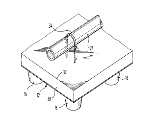
In the case of the embodiment illustrated in Fig. 2, the
spacer plate 12 is formed in the same way as has been
described in connection with Fig. 1. The carrier plate, lying
on the spacer plate 12, consists of a heat insulating layer
30, which for example, consists of polyurethane rigid foam
laminated with a supporting sheet 32. To this carrier plate,
the heating tubes 24 are securely fastened with the help of
clamps 34 sticking through the supporting sheet 32, as is in
itself known. In this case, the carrier plate can also be
glued to the spacer plate so that the surface element so
formed can be installed as a single unit.
As is known, a surface element so formed has a high
carrying capacity which is not lost in the case of a fire. A
heatable hollow space floor can be constructed wherein,
because of the formation of the surface element either with an
isolation layer between the carrier plate and the spacer plate
or without an isolation layer between the two plates,
different possibilities for a combination of in-floor heating
with a ventilating or warm air apparatus are possible.
Whereas, in the embodiment of Fig. 1, two plastic sheets
14 and 20 are used for holding the ceramic supporting bodies
- 6 -
CA 02271579 2000-02-24
and for holding the heating tubes, in the case of the
embodiment of Fig. 3 only a single plastic sheet 36 is
provided in which from one side the truncated cone recesses or
protuberances 38 are provided by deep forming and on the other
side clamping dogs 40 are formed by deep forming for holding
the heating tubes. This sheet can be used in the same way as
the two sheets of Fig. 1. That is, ceramic supporting bodies
can be inserted in the recesses 38 as described in connection
with Fig. 1. In accordance with the solutions of Figs. 3 and
4, one can also, however, spare the insertion of the ceramic
supporting bodies since the heating tube 24 embedding finish
42 upon application will also enter the recesses 38 and
completely fill them. After hardening, the finish then forms
the actual spacer elements, the protuberances 38 of the sheet
36 serving only as molds for the casting of the spacer
elements.