Note: Descriptions are shown in the official language in which they were submitted.
CA 02271624 1999-O1-15
WO 98I03130 PCT/US97/12673
ABUTMENT-MOUNT SYSTEM FOR DENTAL IMPLANTS
BACKGROUND OF THE INVENTION
1. Field of the Invention
The present invention relates to skeletal implants (such as dental implants)
and
more particularly to a dental implant kit that provides an abutment that also
acts as a
mount.
2. Description of the Prior Art
Dental implants are used to provide a platform to which a dental prosthesis
may
be secured to underlying bone in the mandible or maxilla of a dental patient.
A typical
root form dental implant system employs a dental implant that is placed in a
prepared
site in the underlying bone. A disposable mount is used to provide a
connection to an
insertion tool used to place the implant into the bone. If the implant is a
threaded
implant, the mount is typically a removable extension of the implant that
provides a hex
nut-type suface for engagement with a socket used for screwing the implant
into the
prepared site. Once the implant is engaged in the site, the mount is removed
and
discarded. A cover screw is axed to the top of the implant and the bone
surrounding
the prepared site is allowed to grow into the implant for several months,
thereby
securing the implant to the bone.
Once the surrounding bone has sufl'lciently engaged the implant, the cover
screw
is removed and an impression coping is affxed to the implant. An impression of
the
implant and the surrounding teeth is taken and a dental prosthesis is
constructed using
the impression as a model of the area of the patient's mouth surrounding the
implant
site. The dental prosthesis is then affixed to the abutment with cement, or
other affixing
means. Thus, the abutment acts as a platform for securing a dental prosthesis
to the
implant.
CA 02271624 1999-O1-15
WO 98I03130 PCTlUS97/12673
-2-
The current method is wastefi~l and costly because the mount is discarded and
a
separate abutment must be procured.
SUMMARY OF THE INVENTION
The present invention is an abutment-mount for a dental implant, having a
longitudinally extending axis with a first end, an opposite second end and a
peripheral
surface. The abutment-mount is used for delivering the dental implant to a
prepared site
of a jawbone with an implant drive tool and is also used as a device for
securing a dental
prosthesis to the dental implant. The abutment-mount includes a screw, or
other
fastener, for securing the abutment-mount to the implant. A surface is
provided for
attaching the dental prosthesis to the abutment-mount adjacent the first end.
A structure
is provided for transferring rotational force from the implant drive tool to
the implant
through the abutment-mount.
In another aspect of the invention a groove, defined by the peripheral surface
of
the abutment-mount, is disposed circumferentially about the peripheral surface
of the
abutment-mount, thereby providing an attachment surface for cement used to
affix the
dental prosthesis to the abutment-mount adjacent the first end.
Yet another aspect of the invention is a dental implant kit for use with an
implant
drive tool. The kit includes a dental implant having a crestal end defining a
first
engagement surface. The kit also includes an abutment-mount, having a first
end and an
opposite second end, and a peripheral surface, the second end defining a
second
engagement surface matingly engageable with the first engagement surface, the
peripheral surface defining a surface for engagement with the implant drive
tool. The kit
also includes a surface for securing the abutment-mount to the dental implant,
thereby
providing a platform for attachment of a dental prosthesis to the implant.
An additional aspect of the invention provides a method of deploying and using
a
dental implant in prepared site of a bone. The dental implant, having an
abutment-
CA 02271624 1999-O1-15
WO 98I03130 PCT/US97/12673
-3-
mount coupled to the dental implant that transfers any rotational force
received by the
abutment-mount to the dental implant, is placed into the prepared site.
Rotational force
is applied to the abutment-mount with an implant drive tool, thereby rotating
the dental
implant into the prepared site. The abutment-mount is removed from the dental
implant
for a preselected period to allow bone growth into the dental implant, thereby
affixing
the dental implant to the bone. The abutment-mount is re-coupled to the
implant and is
then secured to the dental implant. A dental prosthesis is then affixed to the
abutment-
mount.
In yet another aspect of the invention, longitudinal force is applied to the
abutment-mount with an implant drive tool, thereby driving the dental implant
into the
prepared site.
One advantage of the invention is that the mount used to drive the implant
into
the prepared site is also used as an abutment for securing the prosthesis to
the implant,
thereby reducing the cost of implantation.
Another advantage of the invention is that it provides an abutment that can be
secured in an impression material as part of a direct or indirect impression
technique.
These and other advantages will become apparent from the following description
of the preferred embodiment taken in conjunction with the following drawings,
although
variations and modifications may be effected without departing from the spirit
and scope
of the novel concepts of the disclosure.
BRIEF DESCRIPTION OF THE FIGURES OF THE DRAWINGS
FIG. 1 is an exploded elevational view of an implant, an abutment-mount, an
abutment screw and a socket for engaging the abutment-mount.
FIG. 2 is a top front perspective view of an abutment-mount and a socket.
CA 02271624 1999-O1-15
WO 98I03130 . PCT/ITS97/12673
-4-
FIG. 3 is a cross-sectional view of an implant kit packaged in a vial.
FIG. 4A is a partial cut-away elevational view of a first embodiment of a
socket
for use with a dental hand piece.
FIG. 4B is an elevational view of the socket of FIG. 4A engaged with an
abutment-mount affixed to an implant.
FIG. 5 is a front elevational view of a second embodiment of a socket for use
with a ratchet.
FIG. 6 is a top front perspective view of an implant and an abutment-mount
using an elongated screw as part of a direct impression technique.
DETAILED DESCRIPTION OF THE PREFERRED EMBODIMENTS
A preferred embodiment of the invention is now described in detail. Refernng
to
the drawings, like numbers indicate like parts throughout the views. As used
in the
description herein and throughout the claims that follow, "a," "an," and "the"
includes
plural reference unless the context clearly dictates otherwise. Also, as used
in the
description herein and throughout the claims that follow, the meaning of "in"
includes
"in" and "on" unless the context clearly dictates otherwise. Also,
"complimentary in
shape" means generally having compatible dimensions, without necessarily
having an
identical shape.
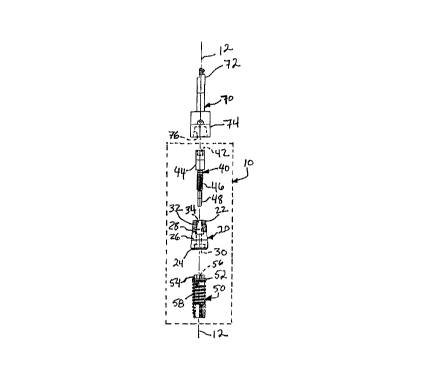
As shown in FIGS. 1 and 2, the implant kit 10 of the present invention
comprises
a dental implant 50, an abutment-mount 20 and an abutment screw 40. The dental
implant 50 may be one of several types, including the screw-type root-form
dental
implant shown. As show, the dental implant 50, the abutment-mount 20 and the
...._ ,~ _. ..r
CA 02271624 1999-O1-15
WO 98I03130 PCT/US97/12673
-5-
abutment screw 40 are all aligned along a common axis 12. The implant 50, the
abutment-mount 20 and abutment screw 40 would be made from a material suitable
for
implant applications, such as ASTM F-136 titanium alloy using a CNC machining
process. As would be obvious to one skilled in the art, other materials and
manufacturing processes may be employed without departing from the scope of
the
invention.
The abutment-mount 20 has a first end 22, an opposite second end 24 and a
peripheral surface 26. At least one drive tool engagement surface 28 is
provided for
engagement with an implant drive tool 70, such as a socket. The engagement
surface 28
could be a flat chordal surface, as shown, or any other of the many types of
drive tool
engagement surfaces that are commonly known to the arts of fastener design and
implantology (for example, an internal hex could be employed for engagement
with an
Allen wrench as a drive tool).
The implant 50 includes a crestal end 52 and a first rotational engagement
surface 54 adj acent the crestal end 52. The crestal end 52 defines a first
longitudinal
opening 56 with internal threads for receiving the abutment screw 40 therein.
The
abutment-mount 20 includes a second rotational engagement surface 30 that is
complimentary in shape to the first rotational engagement surface 54. The
first
rotational engagement surface 54 may be a male polygonal surface (such as a
hexagonal
protrusion) extending from the crestal end 52, with the second rotational
engagement
surface 30 being a corresponding female engagement surface defined by the
second end
24. Similarly, the first rotational engagement surface 54 could be a female
polygonal
surface, while the second rotational engagement surface 30 is a corresponding
male
polygonal surface. As would be obvious, many other types of engagement
surfaces
(including non-polygonal surfaces) could be employed with satisfactory
results.
The abutment-mount 20 may be provided with one or more grooves 32 defined
by the peripheral surface 26 to provide additional surface area on the
abutment-mount
i
CA 02271624 1999-O1-15
WO 98I03130 PCT/US97/12673
-6-
20 for cementing a dental prosthesis (not shown) thereto and for retention of
impression
material. Because the abutment-mount 20 performs both the fi~nction of an
abutment,
for securing a prosthesis to the implant 50, and the fi~nction of a mount, for
driving the
implant 50 into a prepared bone site, the present invention avoids the cost of
supplying
an additional, non-reusable mount.
The abutment-mount 20 is fastened to the implant 50 with the abutment screw
40. The abutment screw 40 may include a head portion 44, a threaded portion 46
and a
non-threaded alignment portion 48 for aligning the threads of the threaded
portion 46
with the threads in the first longitudinal opening 56 of the implant 50. The
head portion
44 defines an internal hex opening 42 for receiving a hex driver for screwing
the
abutment screw 40 into the first longitudinal opening 56 implant 50. The
abutment-
mount 20 defines a second longitudinal opening 34 passing therethrough, for
receiving
the abutment screw 40 therein. The second longitudinal opening 34 includes an
enlarged top part 36 opening to the first end 22 and a narrowed part 38
opening to the
second rotational engagement surface 30. The enlarged top part 36 has a
diameter
sufficient to receive the head portion 44 of the abutment screw 40, while the
narrowed
part 38 has a diameter sufficient to receive the threaded portion 46 of the
abutment
screw 40. The length of the enlarged part 36 is such that the head portion 44
is
substantially flush with the first end 22 of the abutment-mount 20 when the
abutment
screw 40 and the abutment-mount 20 are properly affixed to the implant 50.
As shown in FIG. 3, the implant kit 10, including the implant 50, the abutment-
mount 20 and cover screw 40 may be shipped together in a package 80 comprising
a
vial 82 and a cap 84. The vial 82 may be made of a plastic polymer, such as
polyethylene, or any other suitable material commonly known to the art. At
least one
tab 90 extends outwardly from the cap 84 to prevent rolling of the package 80
when
placed on a flat surface.
CA 02271624 1999-O1-15
WO 98I03130 PCT/LTS97112673
_7_
A detente 88 extends from the center of the inside surface of the cap 84. The
detente 88 is shaped to fit into the second longitudinal opening 34 of the
abutment-
mount 20, so that the detentes 88 holds the kit 10 and prevents the threads 58
of the
implant 50 from touching the inner surface of the vial 82. This is especially
important,
because the threads may be coated with a coating, such as an apatite compound,
that
could flake is touched by the vial 82. The abutment screw 40 is held in place
by a plastic
holder 92 that is polygonally-shaped (e.g. having a hexagonal shape) to
prevent rolling
of the holder and the abutment screw 40 when they are placed on a flat
surface.
As shown in FIGS. 4A & 4B, in one embodiment designed for use with a
standard dental handpiece (not shown), the drive tool 70 used to drive the
implant 50
includes a socket 74 defining an opening 76 that is complimentary in shape to,
and fits
over, the abutment-mount 20. Extending upwardly from the socket 74 is a
fitting 72
that couples to the dental handpiece. The fitting 72 shown herein is designed
to be
coupled to an ISO 1791-1 standard dental handpiece.
In an alternate embodiment, shown in FIG. 5, a drive tool 170 for use with a
ratchet (not shown) may also be used. The drive tool 170 comprises a body
portion
184, for engaging the ratchet, with a socket Z 74 extending downwardly
therefrom and a
finger knurl 182 extending upwardly therefrom. A recess 180 is defined by the
body
portion 184 for receiving therein an O-ring 186. The finger knurl 182 may be
supplied
to give the implantologist the ability to start the implant by hand. The
socket 174
defines a recess 176 that is complimentary in shape to the abutment-mount. The
recess
I76 may be provided with an o-ring 178 that acts as a spacer to allow the
abutment-
mount to be easily disengaged from the socket 174.
As shown in FIG. 6, an elongated screw 190 may be supplied for use as an
impression pin in the direct impression technique. The elongated screw 190
fits into the
second longitudinal opening 34 of the abutment-mount 20 and has a drive
structure 192,
such as an internal hex, for tightening and loosening the elongated screw 190.
In taking
i
CA 02271624 1999-O1-15
WO 98/03130 PCT/US97112673
_g_
an impression using the elongated screw 190, impression material {not shown)
is placed
around the abutment-mount 20 and the elongated screw 190 after the implant 50
has
been driven into the bone. The elongated screw i90 goes through the impression
material and tray so that the drive structure 192 is not covered by the
impression
material. Once the impression material has set, the elongated screw 190 is
removed
from the implant 50 and the impression material and the emplaced abutment-
mount 20 is
removed from the patient's mouth. The grooves 32 on the abutment-mount 20
provide
a surface which improves holding by the impression material. A healing screw
(not
shown) is afl<lxed to the implant 50.
While the bone is affixing the implant, a cast of the area around the implant
50 is
made from the impression material. The abutment-mount 20 may fit into the
cast,
thereby allowing a dental prosthesis to be constructed with the abutment-mount
20
providing a base with the same relationship to the patient's mouth as it will
eventually
have when it is permanently affixed to the implant 50. The drive tool
engagement
surface 28 provides a means of ensuring that the orientation of the abutment-
mount 20
remains the same with respect to the implant 50 at all times. This function
could also be
accomplished by machining a marking onto the abutment-mount 20 to be used as a
reference point. This ensures a near exact fit between the prosthesis, the
abutment-
mount 20 and the patients surrounding teeth.
The above embodiments are given as illustrative examples and are not intended
to impose any limitations on the invention. It will be readily appreciated
that many
deviations may be made from the specific embodiments disclosed in this
specification
without departing from the invention. Accordingly it is intended to cover all
such
modifications as within the scope of this invention.