Note: Descriptions are shown in the official language in which they were submitted.
r
CA 02271803 1999-OS-13
WO 98/Z1420 PCT/N097100~99
1
APPARATUS FOR THE DISTRIBUTION OF WATER OR OTxBR LIQUIDS
The present invention relates to an apparatus for the
distribution of water or other liquids, comprising a tank
with at least one inlet and two or more outlets adapted to
deliver equal amounts of liquid.
This invention in a practical embodiment, concerns a
distribution shaft or tank for water, in particular water
either for infiltration in the soil or for irrigation of
agricultural areas, where it is often desirable to
distribute the water evenly over large areas. Normally the
distribution shaft will be connected to an external water
source, which distributes the water evenly to one or more
outlets. After the setting up of the distribution shaft, its
outlets must be adjusted with accuracy so that the water
flux to the outgoing pipes/channels is distributed
approximately evenly between these. This adjustment is not
easy, as the outlets are usually to be found in the bottom
of a narrow shaft, often two or three meters below ground
level. The adjustment must be carried out, not only at the
setting up of the shaft, but continually through the years
because the least level difference between the lowest point
of the water outlets, where water starts running out to the
outlet pipes from the distribution shaft, entails large
differences in the water volume from the outlet of the
distribution shaft. There are distribution shafts that can
be adjusted from ground level, but this is a time consuming
process Where one has to use tools with long handles, good
lighting and adequate measuring devices. Furthermore,
movable parts have a tendency to jamming, as they are
exposed to influx of sludge to the areas about to be
repaired.
A distribution shaft or tank for infiltration,
involving drawbacks as explained immediately above, is
i
described in Norwegian patent specification No. 151.051.
Also No. 176.976 shows a valve design of some interest in
this connection. Other prior art, being of still less
relevance, is represented by US patents 1.591.453 and
2.518.292.
CA 02271803 1999-OS-13
WO 98121420 PCT/N097100a99
2
There are many reasons why distribution shafts change
their position across'time. It often happens because of
movements in the ground by loose fillers, generally unstable
masses, for example by passage of a tractor nearby. In °'
countries where the ground is normally frozen during certain
periods, this is considered to be the main reason for the
necessary frequent adjustments of distribution shafts.
To overcome the existing drawbacks of distribution
shafts it is therefore an objects of this invention to
l0 provide a new and improved solution which, among other
things, results in automatic adjustment in a distribution
tank, so that there is normally no need for later manual
resetting or adjustment in order to obtain a long-term equal
amount or flow of water in all outlets form the tank.
According to the invention this is obtained primarily by
means of a float body adapted to float on a water reservoir
in the tank and provided with a distribution basin for
receiving liquid from said inlet(s), said distribution basin
having a number of outlet openings corresponding to said
outlets and located at the same level in the distribution
basin and being each adapted to discharge liquid to a
separate outlet.
In other words influxed water or other liquids is
distributed over a stably floating watertight body,
centrally situated and equipped with a basin for reception
and distribution of water.
In a practical embodiment features and functions may be
included as follows: The water volume in the basin varies
with the influx, and entails that the sides of the basin are
kept free from possible sludge. The water then, runs down
through the desired number of outlet openings (distribution
holes) which can be equipped with a known type of V-
overflows. Thereafter the water runs out through elbows of
the outlets, which are connected with other installations.
If the distribution shaft, and therewith also the in- and
outlet devices, are put out of level, the floating body with
its distribution holes will always keep a levelled stable
position on the water phase of the shaft, as it is without
contact with the fixedly installed devices for in- and
CA 02271803 1999-OS-13
WO 9~214Z0 PCT/N097/002l9
3
outlet. The bottom of the water distributing basin is formed
so that it can compensate hydrologically for slantingly
installed inlets, which takes place when the distribution
shaft becomes subject to greater angle deviations. Thus,
preferably the basin bottom has a downward concave shape.
Also, the bottom of the distribution shaft is formed so that
it creates an evenly distributed "splash-effect", resulting
in an improved effect of infiltration pipes and ditches.
This distribution shaft with its floating body compensates
1o for as much as Z5 degrees of angle deviation of the shaft or
tank in all direction.
The invention will he explained more cosely in the
following description with reference to an exemplary
embodiment illustrated in the drawings.
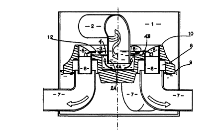
Figure 1 shows the distribution shaft in vertical cross
section after the line a-b on figure 2. The arrows indicate
the direction in which the water runs. Figure 2 shows the
water distribution shaft seen from above. Dotted lines
indicate pipes and cavities, invisible from the top; the
arrows illustrate the direction in which the water runs. The
process of the operation is explained by reference to the
numbers which are noted on the drawing.
The water is fed to the shaft 1 through the inlet 2
which is sunk into th water distribution basin 4 of the
floating body 3 The number 12 shows the water level in the
water distribution basin. From basin 4 water runs radially
out to, and down through, the distribution holes 5. These
have a pipe connection 6 which is situated internally in the
elbow of the outlet pipe 7 and ensures that the water is led
further down into the elbow. Around the pipe connection 6
there are in the horiaontal plane larger circular recesses
or openings 8, so that the inlet to the elbow 7 of the
outlet pipe can extend up within the floating body 3. Thus,
the water level in the shaft J. is determined by the lower-
most elbow 7 or the outlet pipe. Together with the
"headroom" in the circular openings 8, the elbow determines
which position the floating body 3 can occupy before it
touches the ceiling in one or more of the circular openings
8 and thereby losing its capacity for automatic water
a
CA 02271803 1999-OS-13
WO 98121420 PCT/N097/OOZ99
4
distribution. These parameters determine the capacity for
angle deviations, with the limitation that the floating body
3 ought to be very stable, and to obtain that the limitation
has to be larger than heigh:width approx. 1:2.
The distribution holes 5 can in their lower edge have
an approximate V-shaped inlet cross section, as known per
se. The floating body should be smaller than the inner
diameter of the shaft 1. Likewise, there must be sufficient
clearance to the pipe connections to secure free movement.
The circular surrounding wall or elevation 10 ensures that
the water is led to the distribution holes 5. If desired,
the inlet 2 and the floating body 3 can be lifted from their
assembled positions as shown, after removal of a cover (not
shown) on top of the shaft or tank 1. Condensation of water
on the inside of the shaft provides sufficient water for the
movement of the floating body 3. For reasons of balance an
extra circular opening 8 below the inlet .2 is connected
with a ventilation opening 11. This leads out through the
circular elevation 10 to avoid variations in pressure. The
water level 12 in the water distribution basin 4 varies
somewhat with the volume of the induced water, and ensures
rinsing of the slanting sides in the floating body 3.
Although the above description refers to a particular
embodiment according to the invention, it will be understood
that various modifications and specific solutions are
possible. Whereas, e.g., water has been mentioned as the
liquid or liquids involved, also liquids different from
water may be of interest in connection with the distribution
shaft or tank. This not only relates to the liquid flowing
through the tank, but also the reservoir contained in the
tank for supporting the float body, may be some other
specific liquid than water. The particular field of use will
determine what sort of liquid will be involved, such as for '
installations in industrial processing plants.
As regards the relative dimensions and positions of
components incorporated in the tank, a primary concern is
that the float body shall be able to float freely on the
surface of the reservoir liquid, so as to automatically
assume a level or horisontal position at any time. Thus the
CA 02271803 1999-OS-13
wo nni4zo rcrn~o9~ro~
float body preferably has an outer contour running at a
small distance from, but with sufficient clearance in
relation to adjacent inner walls of the tank. Another
- feature related to the freedom of movement of the float body
5 in relation to the stationary tank walls and other fixed
components therein, will be seen in the relatively deep
central part ,4A' of the distribution basin 4 , in which
the inlet pipe '.2 is immersed, as illustrated in fig. 1.
This solution besides will provide for a water lock effect.
At this point it is noted that the bottom of the central
part 4A is shown to be more or less planar in fig. 1. As
indicated above a more hydrologically favourable shape may
be contemplated, in particular by having a downward
curvature of this bottom, so that any skewing of inlet pipe
2 with respect thereto will not result in an undesired flow
pattern in this central part of the distribution basin. In
figs. 1 a,ad 2 five outlets are shown, these being in the
principle regularly distributed around the circumference.
The balanced arrangement thereby established, will be
obtained in a corresponding manner when a different number
of outlets are provided for, e.g. tbree outlets having a
mutual angular spacing of 120°.