Note: Descriptions are shown in the official language in which they were submitted.
CA 02271807 1999-OS-13
CONVEYOR SYSTEM
The present invention relates to conveyor systems.
There are many previously known conveyor systems. In one type of conveyor
system, rollers engage work pieces supported on the conveyor system in order
to
propel the work pieces from one end of the conveyor system and toward the
other
end. In many cases, one or more work stations are positioned along the
conveyor line
in order to perform work of one sort or another upon the work pieces.
These previously known roller conveyor systems typically propel the work
pieces along a generally horizontal plane. In some instances, such as the
assembly
of an automotive body, it is desirable or even necessary to elevate the work
piece
above the plane of the conveyor line at a particular work station and before
the work
is performed on the work piece.
In order to accomplish the elevation of the work piece at a particular work
station, it has been the previously known practice to provide a lifter
assembly beneath
the conveyor line at the work station. Thus, once the work piece is conveyed
to the
work station, activation of the lifter assembly elevates the work piece from a
lower
and to a raised position. These previously known lifter assemblies typically
engage
preset location points on the work piece.
While these previously known lifter assemblies have proven adequate where
the work pieces are identical to each other, and thus have identical location
points for
CA 02271807 1999-OS-13
the lifter assembly, in some cases, different types of work pieces having
different
location points for the lifter assembly are conveyed on a common conveyor
line.
One such example of this latter case is in the assembly of the body for
automotive vehicles. In such conveyor lines, the automotive bodies are
initially
S supported on a skid which is conveyed down the conveyor line. However, since
different automotive bodies may be conveyed by a common conveyor line, it is
oftentimes necessary to provide different lifter assemblies at a single work
station in
order to accommodate these different automotive bodies.
The present invention provides a conveyor system which overcomes all of the
above-mentioned disadvantages of the previously known conveyor systems.
In brief, the conveyor system of the present invention comprises an infeed
conveyor section, and outfeed conveyor section and a working conveyor section
disposed in between the infeed and outfeed sections.
I S The working conveyor section includes a base, a frame and means for
movably securing the frame to the base between a lower position and a raised
position. In the preferred embodiment of the invention, this lifting means
comprises
a driver rotatably mounted about a substantially horizontal axis to the base
and an
elongated drive link having one end pivotally connected to the frame and its
other end
pivotally connected to the driver at a position radially spaced from its axis.
Means
then selectively pivot the driver between a first and second position which
are
angularly spaced apart from each other by substantially 180 degrees and, in
doing so,
moves the frame between its raised and lower position.
2
CA 02271807 1999-OS-13
A primary advantage of applicant's invention is that, since the entire working
conveyor section, together with any work pieces supported by it, are moved
between
a raised and lower position, different types of work pieces can be effectively
conveyed by the conveyor system of the present invention. The present
invention,
however, has proven particularly effective for conveying automotive bodies on
skids.
A better understanding of the present invention will be had upon reference to
the following detailed description, when read in conjunction with the
accompanying
drawing, wherein like reference characters refer to like parts throughout the
several
views, and in which:
FIG. 1 is a side view illustrating a preferred embodiment of the present
invention;
FIG. 2 is a top view illustrating the preferred embodiment of the present
invention;
FIG. 3 is a front view illustrating the preferred embodiment of the present
invention;
FIG. 4 is a front view illustrating the lifting mechanism of the preferred
embodiment of the present invention in a lowered position;
FIG. 5 is a view similar to FIG. 4, but illustrating the lifting mechanism in
a
raised position; and
FIG. 6 is a view taken substantially along line 6-6 in FIG. 5.
3
CA 02271807 1999-OS-13
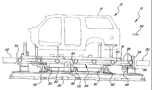
With reference first to FIGS. 1 and 2, a preferred embodiment of the conveyor
system 10 of the present invention is there shown for transporting work pieces
12,
such as an automotive body 14 supported on a skid 16. The conveyor system 10
includes an infeed conveyor section 20, an outfeed conveyor section 22 and a
working conveyor section 24 positioned in between the infeed and outfeed
conveyor
sections 20 and 22, respectively.
In a fashion which will be subsequently described in greater detail, the
working conveyor section 24 is movable between a raised and a lower position.
The
working conveyor section 24 is illustrated in its lower position in FIG. l
and, as such,
the working conveyor section 24 lies on generally the same horizontal plane as
both
the infeed and outfeed conveyor sections 20 and 22, respectively. As such, the
working conveyor 24 receives the work piece 12 from the infeed conveyor 20
and,
upon completion of a work operation, conveys the work piece 12 to the outfeed
conveyor 22.
Still referring to FIGS. 1 and 2, the working conveyor section 24 includes a
base 26 which is mounted to a ground support surface and a frame 28 which is
vertically movably mounted relative to the base 26 by vertical bearings 30
(FIG. 1).
The vertical bearings 30 are conventional in construction and permit vertical
movement of the frame 28 relative to its base 26 but prevent either lateral or
longitudinal movement of the frame 28 relative to its base 26.
Any conventional means can be employed to convey the work piece 12 along
the working conveyor section 24. However, in the preferred embodiment of the
4
CA 02271807 1999-OS-13
invention, the frame 28 includes a pair of elongated and spaced apart rails 32
which
are secured together by end cross supports 34. A plurality of longitudinally
spaced
apart roller assemblies 36 are rotatably mounted by individual axles 38 to the
rails 32
such that each roller assembly 36 includes one roller 40 extending laterally
outwardly
S from each rail 32. These rollers 40 engage and support the bottom of the
skid 16
(FIG. 1 ).
A motor 44 (FIG. 2) is drivingly connected to one of the roller assemblies 36'
via a drive belt 46. Additional drive belts 48 then extend between the roller
assembly
36' and the other roller assemblies 36 such that, upon activation of the motor
44 by
a control system 50, the rollers 40 are rotatably driven in synchronism with
each
other. In doing so, the rollers 40 propel the work piece 12 (FIG. 1) supported
by the
rollers 40 in the direction of arrow 52 (FIG. 1).
In the preferred embodiment, the rollers 40 include a polyurethane outer
coating which contacts and supports the work piece 12 and/or skid 16. The
polyurethane coating on the rollers enhances the frictional engagement between
the
work piece 12 and the rollers 40 to permit rapid acceleration and deceleration
of the
work piece 12 by the motor 44. It will be understood, of course, that during
the
actual operation of the working conveyor section 24, the work pieces 12 are
typically
moved from the infeed conveyor section 20 to the working conveyor section 24
and
then stopped during a work operation. Following completion of the work
operation,
the motor 44 is again actuated thus propelling the work piece 12 onto the
outfeed
conveyor section 22.
5
CA 02271807 1999-OS-13
With reference now to FIGS. 4-6, a lifting assembly 60 is there shown for
lifting the frame between a lower position, illustrated in FIG. 4 and in solid
line in
FIG. 6 and a raised position, illustrated in FIG. 5 and in phantom line in
FIG. 6. The
lifting assembly 60 includes a pair of drive assemblies 62 such that one drive
assembly 62 is positioned adjacent each end of the working conveyor section
24.
Each drive assembly 62 comprises a pair of drivers 64 which are secured to
opposite ends of a shaft 66. The shaft 66, in turn, is rotatably mounted by
spaced
bearing assemblies 68 to the base 26 so that the shaft 66, and thus the
drivers 64, are
rotatable about a generally horizontal axis 70.
Still referring to FIGS. 4-6, an elongated drive link 72 is associated with
each
driver 64. The drive link 72 has one end 74 pivotally connected to its
associated
driver 64 at a position parallel to but radially spaced from the driver
rotational axis
70. The other end 74 of the drive link 72 is pivotally connected to the frame
28.
With reference now to FIGS. 1 and 5, any conventional means 80 can be
utilized for selectively pivoting the shaft 66, and thus the drivers 64,
between a first
and second position which are angularly spaced from each other by
substantially 180
degrees. However, as shown in the preferred embodiment, a controllable motor
82
is driveably connected by a belt 84 to drive the shaft 66.
Actuation of the motor 82 to drive the drivers 64 between their first
position,
illustrated in FIG. 4 and in solid line in FIG. 6, and their second position,
illustrated
in FIG. 5 and in phantom line in FIG. 6, simultaneously moves the frame 28
from its
lower and to its upper position. Following conclusion of the work operation,
the
motor 82 is again actuated to return the drivers 64 to their first position
again
6
CA 02271807 1999-OS-13
lowering the frame 28 to its lower position to enable the working conveyor
section
24 to transfer the work piece 12 to the outfeed conveyor section 22.
Even though the working conveyor section 24 is preferably used to selectively
raise the work piece during a work operation and then lower the work piece to
be
coplanar with the outfeed conveyor section, it will be understood, of course,
that the
working conveyor section 24 can alternatively be used to raise the work piece
12
from a lower plane of the infeed conveyor section 22 to a higher plane for the
outfeed
conveyor section 22.
Having described my invention, however, many modifications thereto will
become apparent to those skilled in the art to which it pertains without
deviation from
the spirit of the invention as defined by the scope of the appended claims.
7