Language selection

Search

Patent 2272171 Summary

Third-party information liability

Some of the information on this Web page has been provided by external sources. The Government of Canada is not responsible for the accuracy, reliability or currency of the information supplied by external sources. Users wishing to rely upon this information should consult directly with the source of the information. Content provided by external sources is not subject to official languages, privacy and accessibility requirements.

Claims and Abstract availability

Any discrepancies in the text and image of the Claims and Abstract are due to differing posting times. Text of the Claims and Abstract are posted:

  • At the time the application is open to public inspection;
  • At the time of issue of the patent (grant).
(12) Patent: (11) CA 2272171
(54) English Title: SEAL ARRANGEMENT
(54) French Title: DISPOSITIF D'ETANCHEITE
Status: Term Expired - Post Grant Beyond Limit
Bibliographic Data
(51) International Patent Classification (IPC):
  • F16J 15/34 (2006.01)
  • F04B 53/00 (2006.01)
  • F04D 29/12 (2006.01)
(72) Inventors :
  • BRATTHALL, JOHAN (Sweden)
(73) Owners :
  • ITT MANUFACTURING ENTERPRISES, INC.
(71) Applicants :
  • ITT MANUFACTURING ENTERPRISES, INC. (United States of America)
(74) Agent: SMART & BIGGAR LP
(74) Associate agent:
(45) Issued: 2004-01-20
(22) Filed Date: 1999-05-17
(41) Open to Public Inspection: 1999-11-18
Examination requested: 1999-05-17
Availability of licence: N/A
Dedicated to the Public: N/A
(25) Language of filing: English

Patent Cooperation Treaty (PCT): No

(30) Application Priority Data:
Application No. Country/Territory Date
9801731-2 (Sweden) 1998-05-18

Abstracts

English Abstract

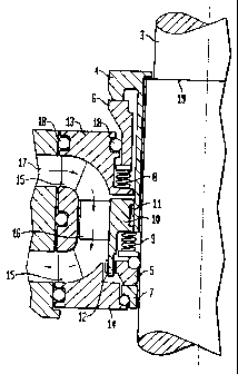
The invention concerns a seal device for a submersible machine, such as a pump or a mixer. The seal device is designed as an easily replaceable unit comprising two mechanical face seals (4,6) and (5,7) resp. with an intermediate room for a barrier liquid in which a pump for circulation of said liquid is arranged. A spring housing (10) which serves as a uniting means for the seal device is provided with connecting means for the rotary seal rings (4) and (5) resp. and acts as a hub for impeller vanes (16) in said circulation pump.


French Abstract

L'invention concerne un dispositif de joint d'étanchéité pour une machine submersible, telle qu'une pompe ou un mélangeur. Le dispositif de joint d'étanchéité est conçu sous la forme d'une unité facilement remplaçable comprenant deux joints faciaux mécaniques (4, 6) et (5, 7) respectivement avec un espace intermédiaire pour un liquide barrière dans lequel est agencée une pompe pour la circulation dudit liquide. Un logement de ressort (10) qui sert de moyen d'unification pour le dispositif d'étanchéité est muni de moyens de raccordement pour les anneaux d'étanchéité rotatifs (4) et (5) respectivement et agit comme un moyeu pour des pales d'hélice (16) dans ladite pompe de circulation.

Claims

Note: Claims are shown in the official language in which they were submitted.

5
CLAIMS:
1. A seal device in the form of an easily exchangable
unit for a rotary driving shaft between an electric motor
and a hydraulic unit, the seal device comprising:
first and second mechanical face seals having an
intermediate room for a barrier liquid, the first mechanical
face seal including a first stationary seal ring and a first
rotary seal ring, the second mechanical face seal including
a second stationary seal ring and a second rotary seal ring;
a pump for circulating the barrier liquid, the
pump having an outer pump housing wall;
a cylindric spring housing that rotates with the
shaft when the seal device is associated therewith, the
spring housing connected to the first rotary seal ring with
a first driver, the spring housing including a second driver
for driving the second rotary seal ring, the spring housing
operating as a seat for a biasing element that urges the
second rotary seal ring towards the second stationary seal
ring, the spring housing further operating as a hub for
vanes in the pump for circulation of the barrier liquid, the
outer pump housing wall of the pump formed by first and
second holders which are respectively for the first and
second stationary seal rings.
2. The seal device according to claim 1, where the
hydraulic unit comprises a submersible pump.
3. The seal device according to claim 2, wherein the
submersible pump includes one of an impeller and a
propeller.

6
4. The seal device according to claim 1, wherein the
hydraulic unit comprises a mixer.
5. The seal device according to claim 4, wherein the
mixer includes one of an impeller and a propeller.

Description

Note: Descriptions are shown in the official language in which they were submitted.


CA 02272171 1999-OS-17
w BRATTHALL-4
SEAL ARRALVGEMENT
The present invention concerns a device for a submersible machine, such as a
pump, a turbine or a mixer.
A machine of this type normally includes an electrically driven motor and a
hydraulic
unit with an impeller connected to the motor via a rotary driving shaft.
In order to prevent the medium within the hydraulic unit from flowing along
the shaft
and penetrate the electric motor and cause damage, one or several seals are
arranged between the motor and the hydraulic unit. A common type of seal is
the
so-called mechanical face seal, which comprises one seal ring rotating with
the shaft
and one stationary seal ring mounted in the surrounding housing. The two rings
are
pressed together by spring force thus preventing medium from penetrating
between
them.
If the medium within the hydraulic unit contains pollutants, a special problem
occurs.
As the pressure within the hydraulic unit is higher, pollutants may penetrate
between
the seal surfaces an cause damage, meaning that the seal result deteriorates
or fails
totally.
In order to solve this problem it is common to arrange two mechanical seals
with an
intermediate room filled with a barrier liquid such as oil, which lubricates
and cools
the surfaces. By this the seal adjacent the electric motor will always operate
with a
clean medium and thus the risks for damages will decrease drastically. If the
seal
adjacent the hydraulic unit should be damaged, medium from said unit may enter
the
barrier liquid room, but by controlling said liquid at regular intervals, the
seal could be
repaired or replaced before any serious damage has accured. An example on such
a
design is shown in the Swedish patent No 381 318.

CA 02272171 2003-03-17
74156-15
2
If it has been noted that the barrier liquid has
been too diluted by the medium in the hydraulic unit, the
seal adjacent said unit must be replaced. If the dilution
has been considerable, there is a risk that also the other
seal has been damaged and therefore it might be preferable
to replace both seals at the same time.
In order to make such a replacement easier, it has
been suggested to arrange them in one single unit which
makes service easier and increases the reliability.
Examples on such designs are shown in the Swedish patents
200 144 and 466 925.
In order to obtain a good circulation of the
barrier liquid within the seal unit, it has been suggested
to arrange a pump within the latter. Especially in a case
where it has been chosen to use a closed cooling system for
the electric motor using the barrier liquid as a coolant, a
pump is necessary if a sufficent flow should be obtained.
Known designs such as those shown in the Swedish
patent 327 904 have however certain disadvantages concerning
space demand and efficiency. This invention concerns a
device which in an effective and secure way obtains the
necessary circulation even at a low rotation speed and which
has a very limited space demand.
In one broad aspect of the invention, there is
provided a seal device in the form of an easily exchangeable
unit for a rotary driving shaft between an electric motor
and a hydraulic unit, the seal device comprising: first and
second mechanical face seals having an intermediate room for
a barrier liquid, the first mechanical face seal including a
first stationary seal ring and a first rotary seal ring, the

CA 02272171 2003-03-17
74156-15
2a
second mechanical face seal including a second stationary seal
ring and a second rotary seal ring; a pump for circulating the
barrier liquid, the pump having an outer pump housing wall; a
cylindric spring housing that rotates with the shaft when the
seal device is associated therewith, the spring housing
connected to the first rotary seal ring with a first driver,
the spring housing including a second driver for driving the
second rotary seal ring, the spring housing operating as a
seat for a biasing element that urges the second rotary seal
ring towards the second stationary seal ring, the spring
housing further operating as a hub for vanes in the pump for
circulation of the barrier liquid, the outer pump housing wall
of the pump formed by the first and second holders which are
respectively for the first and second stationary seal rings.
The invention is disclosed more closely below with
reference to the enclosed drawings. Fig 1 shows a cut
through a pump unit provided with a seal arrangement
according to the invention, while Fig 2 is a principle
sketch of the seal device with an integrated pump.
In the drawings 1 stands for a motor unit, 2 a
hydraulic unit and 3 a driving shaft between the two. 4 and
5 stand for rotary seal rings, 6 and 7 stationary seal
rings. 8 and 9 stand for springs, 10 a spring housing, 11
and 12 drivers, 13 and 14 holders for the stationary seal
rings 6 and 7. 15 stands for stationary vanes, 16 an
impeller vane, 17 a channel for medium, 18 o-rings and 19 a
shoulder on the shaft 3.
The driving shaft 3 between the motor 1 and the
hydraulic unit 2 is thus sealed-off by two mechanical face
seals, 4, 6 and 5, 7 resp. The first, called the outer
seal, is

CA 02272171 1999-OS-17
'' ' 3
located close to the hydraulic unit, while the second, called the inner seal,
is located
close to the motor.
The seal rings 4 and 5 rotate with the shaft and are presed towards the
stationary
seal rings 6 and 7 resp. by spring force. In this way the medium within the
hydraulic
unit is effectively prevented from passing the seal area and penetrate the
motor.
As previously mentioned, the seal device is designed as an easily replaceable
unit.
Said unit is slid onto the shaft 3 until it reaches a position decided by a
shoulder 19
on the shaft, which shoulder supports the rotary seal ring 4 of the outer
seal. Said
replaceable unit includes the seals 4,6 and 5, 7, a uniting spring housing 10
and
holders 13 and 14 for the stationary seal rings 6 and 7.
The spring housing 10 is attached to the rotary seal ring 4 of the outer seal
by help of
snap-in means 11. As the seal ring 4 is in alignment with the shoulder 19 on
the
shaft 3, the spring housing will also be locked on the shaft and is prevented
from
moving in the direction of the motor 1. Said spring housing is also provided
with a
driver 12 for the rotary seal ring 5 of the inner seal and provides a seat for
the spring
means 9 which urges said ring towards the stationary ring 7 of said inner
seal.
Thanks to this design of the spring housing, a compact unit is obtained which
has a
minimum axial extension.
As previously mensioned, the seal unit also includes means for providing a
circulation of the barrier medium, which medium also may be used as a coolant
for
the motor. In order to obtain this circulation, the spring housing 10
constitutes a hub
for a number of impeller vanes 16 which rotate in an axial pump housing
created by
the holders 13 and 14 for the stationary seal rings 6 and 7 resp. Said holders
being
connected by means 15 which simultanously act as stationary vanes in said pump
housing.
According to the invention, a seal device designed as a compact unit is
obtained,
which is easy to exchange in the machine where it is operating and which is
easy to

CA 02272171 1999-OS-17
'' ' 4
mount to a well-defined position on the driving shaft thanks to the shoulder
mentioned. The unit includes a pump for circulation of the barrier medium
within the
seal, which medium also may serve as a coolant for the motor.

Representative Drawing
A single figure which represents the drawing illustrating the invention.
Administrative Status

2024-08-01:As part of the Next Generation Patents (NGP) transition, the Canadian Patents Database (CPD) now contains a more detailed Event History, which replicates the Event Log of our new back-office solution.

Please note that "Inactive:" events refers to events no longer in use in our new back-office solution.

For a clearer understanding of the status of the application/patent presented on this page, the site Disclaimer , as well as the definitions for Patent , Event History , Maintenance Fee  and Payment History  should be consulted.

Event History

Description Date
Inactive: Expired (new Act pat) 2019-05-17
Change of Address or Method of Correspondence Request Received 2018-03-28
Grant by Issuance 2004-01-20
Inactive: Cover page published 2004-01-19
Inactive: Final fee received 2003-11-04
Pre-grant 2003-11-04
Notice of Allowance is Issued 2003-10-08
Letter Sent 2003-10-08
Notice of Allowance is Issued 2003-10-08
Inactive: Office letter 2003-10-07
Inactive: Delete abandonment 2003-10-07
Inactive: Correspondence - Prosecution 2003-09-25
Inactive: Abandoned - No reply to s.30(2) Rules requisition 2003-07-08
Inactive: Approved for allowance (AFA) 2003-04-30
Amendment Received - Voluntary Amendment 2003-03-17
Inactive: S.30(2) Rules - Examiner requisition 2003-01-08
Amendment Received - Voluntary Amendment 2002-06-10
Application Published (Open to Public Inspection) 1999-11-18
Inactive: Cover page published 1999-11-17
Inactive: IPC assigned 1999-07-02
Inactive: First IPC assigned 1999-07-02
Inactive: IPC assigned 1999-07-02
Inactive: Filing certificate - RFE (English) 1999-06-16
Filing Requirements Determined Compliant 1999-06-16
Letter Sent 1999-06-16
Application Received - Regular National 1999-06-16
Request for Examination Requirements Determined Compliant 1999-05-17
All Requirements for Examination Determined Compliant 1999-05-17

Abandonment History

There is no abandonment history.

Maintenance Fee

The last payment was received on 2003-01-30

Note : If the full payment has not been received on or before the date indicated, a further fee may be required which may be one of the following

  • the reinstatement fee;
  • the late payment fee; or
  • additional fee to reverse deemed expiry.

Please refer to the CIPO Patent Fees web page to see all current fee amounts.

Owners on Record

Note: Records showing the ownership history in alphabetical order.

Current Owners on Record
ITT MANUFACTURING ENTERPRISES, INC.
Past Owners on Record
JOHAN BRATTHALL
Past Owners that do not appear in the "Owners on Record" listing will appear in other documentation within the application.
Documents

To view selected files, please enter reCAPTCHA code :


To view images, click a link in the Document Description column. To download the documents, select one or more checkboxes in the first column and then click the "Download Selected in PDF format (Zip Archive)" or the "Download Selected as Single PDF" button.

List of published and non-published patent-specific documents on the CPD .

If you have any difficulty accessing content, you can call the Client Service Centre at 1-866-997-1936 or send them an e-mail at CIPO Client Service Centre.


Document
Description 
Date
(yyyy-mm-dd) 
Number of pages   Size of Image (KB) 
Representative drawing 1999-10-29 1 11
Description 2003-03-17 5 188
Claims 2003-03-17 2 46
Representative drawing 2003-12-18 1 11
Cover Page 2003-12-18 2 39
Description 1999-05-17 4 146
Abstract 1999-05-17 1 14
Claims 1999-05-17 1 28
Drawings 1999-05-17 2 34
Cover Page 1999-10-29 1 33
Drawings 2002-06-10 2 27
Courtesy - Certificate of registration (related document(s)) 1999-06-16 1 116
Filing Certificate (English) 1999-06-16 1 165
Reminder of maintenance fee due 2001-01-18 1 112
Commissioner's Notice - Application Found Allowable 2003-10-08 1 159
Correspondence 2003-10-07 1 12
Correspondence 2003-11-04 1 32