Sélection de la langue

Search

Sommaire du brevet 2272171 

Énoncé de désistement de responsabilité concernant l'information provenant de tiers

Une partie des informations de ce site Web a été fournie par des sources externes. Le gouvernement du Canada n'assume aucune responsabilité concernant la précision, l'actualité ou la fiabilité des informations fournies par les sources externes. Les utilisateurs qui désirent employer cette information devraient consulter directement la source des informations. Le contenu fourni par les sources externes n'est pas assujetti aux exigences sur les langues officielles, la protection des renseignements personnels et l'accessibilité.

Disponibilité de l'Abrégé et des Revendications

L'apparition de différences dans le texte et l'image des Revendications et de l'Abrégé dépend du moment auquel le document est publié. Les textes des Revendications et de l'Abrégé sont affichés :

  • lorsque la demande peut être examinée par le public;
  • lorsque le brevet est émis (délivrance).
(12) Brevet: (11) CA 2272171
(54) Titre français: DISPOSITIF D'ETANCHEITE
(54) Titre anglais: SEAL ARRANGEMENT
Statut: Durée expirée - au-delà du délai suivant l'octroi
Données bibliographiques
(51) Classification internationale des brevets (CIB):
  • F16J 15/34 (2006.01)
  • F04B 53/00 (2006.01)
  • F04D 29/12 (2006.01)
(72) Inventeurs :
  • BRATTHALL, JOHAN (Suède)
(73) Titulaires :
  • ITT MANUFACTURING ENTERPRISES, INC.
(71) Demandeurs :
  • ITT MANUFACTURING ENTERPRISES, INC. (Etats-Unis d'Amérique)
(74) Agent: SMART & BIGGAR LP
(74) Co-agent:
(45) Délivré: 2004-01-20
(22) Date de dépôt: 1999-05-17
(41) Mise à la disponibilité du public: 1999-11-18
Requête d'examen: 1999-05-17
Licence disponible: S.O.
Cédé au domaine public: S.O.
(25) Langue des documents déposés: Anglais

Traité de coopération en matière de brevets (PCT): Non

(30) Données de priorité de la demande:
Numéro de la demande Pays / territoire Date
9801731-2 (Suède) 1998-05-18

Abrégés

Abrégé français

L'invention concerne un dispositif de joint d'étanchéité pour une machine submersible, telle qu'une pompe ou un mélangeur. Le dispositif de joint d'étanchéité est conçu sous la forme d'une unité facilement remplaçable comprenant deux joints faciaux mécaniques (4, 6) et (5, 7) respectivement avec un espace intermédiaire pour un liquide barrière dans lequel est agencée une pompe pour la circulation dudit liquide. Un logement de ressort (10) qui sert de moyen d'unification pour le dispositif d'étanchéité est muni de moyens de raccordement pour les anneaux d'étanchéité rotatifs (4) et (5) respectivement et agit comme un moyeu pour des pales d'hélice (16) dans ladite pompe de circulation.


Abrégé anglais

The invention concerns a seal device for a submersible machine, such as a pump or a mixer. The seal device is designed as an easily replaceable unit comprising two mechanical face seals (4,6) and (5,7) resp. with an intermediate room for a barrier liquid in which a pump for circulation of said liquid is arranged. A spring housing (10) which serves as a uniting means for the seal device is provided with connecting means for the rotary seal rings (4) and (5) resp. and acts as a hub for impeller vanes (16) in said circulation pump.

Revendications

Note : Les revendications sont présentées dans la langue officielle dans laquelle elles ont été soumises.


5
CLAIMS:
1. A seal device in the form of an easily exchangable
unit for a rotary driving shaft between an electric motor
and a hydraulic unit, the seal device comprising:
first and second mechanical face seals having an
intermediate room for a barrier liquid, the first mechanical
face seal including a first stationary seal ring and a first
rotary seal ring, the second mechanical face seal including
a second stationary seal ring and a second rotary seal ring;
a pump for circulating the barrier liquid, the
pump having an outer pump housing wall;
a cylindric spring housing that rotates with the
shaft when the seal device is associated therewith, the
spring housing connected to the first rotary seal ring with
a first driver, the spring housing including a second driver
for driving the second rotary seal ring, the spring housing
operating as a seat for a biasing element that urges the
second rotary seal ring towards the second stationary seal
ring, the spring housing further operating as a hub for
vanes in the pump for circulation of the barrier liquid, the
outer pump housing wall of the pump formed by first and
second holders which are respectively for the first and
second stationary seal rings.
2. The seal device according to claim 1, where the
hydraulic unit comprises a submersible pump.
3. The seal device according to claim 2, wherein the
submersible pump includes one of an impeller and a
propeller.

6
4. The seal device according to claim 1, wherein the
hydraulic unit comprises a mixer.
5. The seal device according to claim 4, wherein the
mixer includes one of an impeller and a propeller.

Description

Note : Les descriptions sont présentées dans la langue officielle dans laquelle elles ont été soumises.

CA 02272171 1999-OS-17
w BRATTHALL-4
SEAL ARRALVGEMENT
The present invention concerns a device for a submersible machine, such as a
pump, a turbine or a mixer.
A machine of this type normally includes an electrically driven motor and a
hydraulic
unit with an impeller connected to the motor via a rotary driving shaft.
In order to prevent the medium within the hydraulic unit from flowing along
the shaft
and penetrate the electric motor and cause damage, one or several seals are
arranged between the motor and the hydraulic unit. A common type of seal is
the
so-called mechanical face seal, which comprises one seal ring rotating with
the shaft
and one stationary seal ring mounted in the surrounding housing. The two rings
are
pressed together by spring force thus preventing medium from penetrating
between
them.
If the medium within the hydraulic unit contains pollutants, a special problem
occurs.
As the pressure within the hydraulic unit is higher, pollutants may penetrate
between
the seal surfaces an cause damage, meaning that the seal result deteriorates
or fails
totally.
In order to solve this problem it is common to arrange two mechanical seals
with an
intermediate room filled with a barrier liquid such as oil, which lubricates
and cools
the surfaces. By this the seal adjacent the electric motor will always operate
with a
clean medium and thus the risks for damages will decrease drastically. If the
seal
adjacent the hydraulic unit should be damaged, medium from said unit may enter
the
barrier liquid room, but by controlling said liquid at regular intervals, the
seal could be
repaired or replaced before any serious damage has accured. An example on such
a
design is shown in the Swedish patent No 381 318.

CA 02272171 2003-03-17
74156-15
2
If it has been noted that the barrier liquid has
been too diluted by the medium in the hydraulic unit, the
seal adjacent said unit must be replaced. If the dilution
has been considerable, there is a risk that also the other
seal has been damaged and therefore it might be preferable
to replace both seals at the same time.
In order to make such a replacement easier, it has
been suggested to arrange them in one single unit which
makes service easier and increases the reliability.
Examples on such designs are shown in the Swedish patents
200 144 and 466 925.
In order to obtain a good circulation of the
barrier liquid within the seal unit, it has been suggested
to arrange a pump within the latter. Especially in a case
where it has been chosen to use a closed cooling system for
the electric motor using the barrier liquid as a coolant, a
pump is necessary if a sufficent flow should be obtained.
Known designs such as those shown in the Swedish
patent 327 904 have however certain disadvantages concerning
space demand and efficiency. This invention concerns a
device which in an effective and secure way obtains the
necessary circulation even at a low rotation speed and which
has a very limited space demand.
In one broad aspect of the invention, there is
provided a seal device in the form of an easily exchangeable
unit for a rotary driving shaft between an electric motor
and a hydraulic unit, the seal device comprising: first and
second mechanical face seals having an intermediate room for
a barrier liquid, the first mechanical face seal including a
first stationary seal ring and a first rotary seal ring, the

CA 02272171 2003-03-17
74156-15
2a
second mechanical face seal including a second stationary seal
ring and a second rotary seal ring; a pump for circulating the
barrier liquid, the pump having an outer pump housing wall; a
cylindric spring housing that rotates with the shaft when the
seal device is associated therewith, the spring housing
connected to the first rotary seal ring with a first driver,
the spring housing including a second driver for driving the
second rotary seal ring, the spring housing operating as a
seat for a biasing element that urges the second rotary seal
ring towards the second stationary seal ring, the spring
housing further operating as a hub for vanes in the pump for
circulation of the barrier liquid, the outer pump housing wall
of the pump formed by the first and second holders which are
respectively for the first and second stationary seal rings.
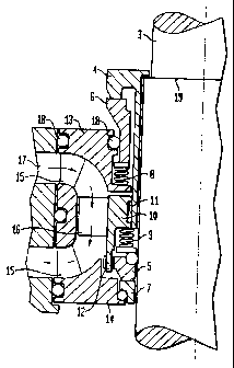
The invention is disclosed more closely below with
reference to the enclosed drawings. Fig 1 shows a cut
through a pump unit provided with a seal arrangement
according to the invention, while Fig 2 is a principle
sketch of the seal device with an integrated pump.
In the drawings 1 stands for a motor unit, 2 a
hydraulic unit and 3 a driving shaft between the two. 4 and
5 stand for rotary seal rings, 6 and 7 stationary seal
rings. 8 and 9 stand for springs, 10 a spring housing, 11
and 12 drivers, 13 and 14 holders for the stationary seal
rings 6 and 7. 15 stands for stationary vanes, 16 an
impeller vane, 17 a channel for medium, 18 o-rings and 19 a
shoulder on the shaft 3.
The driving shaft 3 between the motor 1 and the
hydraulic unit 2 is thus sealed-off by two mechanical face
seals, 4, 6 and 5, 7 resp. The first, called the outer
seal, is

CA 02272171 1999-OS-17
'' ' 3
located close to the hydraulic unit, while the second, called the inner seal,
is located
close to the motor.
The seal rings 4 and 5 rotate with the shaft and are presed towards the
stationary
seal rings 6 and 7 resp. by spring force. In this way the medium within the
hydraulic
unit is effectively prevented from passing the seal area and penetrate the
motor.
As previously mentioned, the seal device is designed as an easily replaceable
unit.
Said unit is slid onto the shaft 3 until it reaches a position decided by a
shoulder 19
on the shaft, which shoulder supports the rotary seal ring 4 of the outer
seal. Said
replaceable unit includes the seals 4,6 and 5, 7, a uniting spring housing 10
and
holders 13 and 14 for the stationary seal rings 6 and 7.
The spring housing 10 is attached to the rotary seal ring 4 of the outer seal
by help of
snap-in means 11. As the seal ring 4 is in alignment with the shoulder 19 on
the
shaft 3, the spring housing will also be locked on the shaft and is prevented
from
moving in the direction of the motor 1. Said spring housing is also provided
with a
driver 12 for the rotary seal ring 5 of the inner seal and provides a seat for
the spring
means 9 which urges said ring towards the stationary ring 7 of said inner
seal.
Thanks to this design of the spring housing, a compact unit is obtained which
has a
minimum axial extension.
As previously mensioned, the seal unit also includes means for providing a
circulation of the barrier medium, which medium also may be used as a coolant
for
the motor. In order to obtain this circulation, the spring housing 10
constitutes a hub
for a number of impeller vanes 16 which rotate in an axial pump housing
created by
the holders 13 and 14 for the stationary seal rings 6 and 7 resp. Said holders
being
connected by means 15 which simultanously act as stationary vanes in said pump
housing.
According to the invention, a seal device designed as a compact unit is
obtained,
which is easy to exchange in the machine where it is operating and which is
easy to

CA 02272171 1999-OS-17
'' ' 4
mount to a well-defined position on the driving shaft thanks to the shoulder
mentioned. The unit includes a pump for circulation of the barrier medium
within the
seal, which medium also may serve as a coolant for the motor.

Dessin représentatif
Une figure unique qui représente un dessin illustrant l'invention.
États administratifs

2024-08-01 : Dans le cadre de la transition vers les Brevets de nouvelle génération (BNG), la base de données sur les brevets canadiens (BDBC) contient désormais un Historique d'événement plus détaillé, qui reproduit le Journal des événements de notre nouvelle solution interne.

Veuillez noter que les événements débutant par « Inactive : » se réfèrent à des événements qui ne sont plus utilisés dans notre nouvelle solution interne.

Pour une meilleure compréhension de l'état de la demande ou brevet qui figure sur cette page, la rubrique Mise en garde , et les descriptions de Brevet , Historique d'événement , Taxes périodiques et Historique des paiements devraient être consultées.

Historique d'événement

Description Date
Inactive : Périmé (brevet - nouvelle loi) 2019-05-17
Requête pour le changement d'adresse ou de mode de correspondance reçue 2018-03-28
Accordé par délivrance 2004-01-20
Inactive : Page couverture publiée 2004-01-19
Inactive : Taxe finale reçue 2003-11-04
Préoctroi 2003-11-04
Un avis d'acceptation est envoyé 2003-10-08
Lettre envoyée 2003-10-08
Un avis d'acceptation est envoyé 2003-10-08
Inactive : Lettre officielle 2003-10-07
Inactive : Supprimer l'abandon 2003-10-07
Inactive : Correspondance - Poursuite 2003-09-25
Inactive : Abandon. - Aucune rép dem par.30(2) Règles 2003-07-08
Inactive : Approuvée aux fins d'acceptation (AFA) 2003-04-30
Modification reçue - modification volontaire 2003-03-17
Inactive : Dem. de l'examinateur par.30(2) Règles 2003-01-08
Modification reçue - modification volontaire 2002-06-10
Demande publiée (accessible au public) 1999-11-18
Inactive : Page couverture publiée 1999-11-17
Inactive : CIB attribuée 1999-07-02
Inactive : CIB en 1re position 1999-07-02
Inactive : CIB attribuée 1999-07-02
Inactive : Certificat de dépôt - RE (Anglais) 1999-06-16
Exigences de dépôt - jugé conforme 1999-06-16
Lettre envoyée 1999-06-16
Demande reçue - nationale ordinaire 1999-06-16
Exigences pour une requête d'examen - jugée conforme 1999-05-17
Toutes les exigences pour l'examen - jugée conforme 1999-05-17

Historique d'abandonnement

Il n'y a pas d'historique d'abandonnement

Taxes périodiques

Le dernier paiement a été reçu le 2003-01-30

Avis : Si le paiement en totalité n'a pas été reçu au plus tard à la date indiquée, une taxe supplémentaire peut être imposée, soit une des taxes suivantes :

  • taxe de rétablissement ;
  • taxe pour paiement en souffrance ; ou
  • taxe additionnelle pour le renversement d'une péremption réputée.

Veuillez vous référer à la page web des taxes sur les brevets de l'OPIC pour voir tous les montants actuels des taxes.

Titulaires au dossier

Les titulaires actuels et antérieures au dossier sont affichés en ordre alphabétique.

Titulaires actuels au dossier
ITT MANUFACTURING ENTERPRISES, INC.
Titulaires antérieures au dossier
JOHAN BRATTHALL
Les propriétaires antérieurs qui ne figurent pas dans la liste des « Propriétaires au dossier » apparaîtront dans d'autres documents au dossier.
Documents

Pour visionner les fichiers sélectionnés, entrer le code reCAPTCHA :


Pour visualiser une image, cliquer sur un lien dans la colonne description du document. Pour télécharger l'image (les images), cliquer l'une ou plusieurs cases à cocher dans la première colonne et ensuite cliquer sur le bouton "Télécharger sélection en format PDF (archive Zip)" ou le bouton "Télécharger sélection (en un fichier PDF fusionné)".

Liste des documents de brevet publiés et non publiés sur la BDBC .

Si vous avez des difficultés à accéder au contenu, veuillez communiquer avec le Centre de services à la clientèle au 1-866-997-1936, ou envoyer un courriel au Centre de service à la clientèle de l'OPIC.


Description du
Document 
Date
(aaaa-mm-jj) 
Nombre de pages   Taille de l'image (Ko) 
Dessin représentatif 1999-10-29 1 11
Description 2003-03-17 5 188
Revendications 2003-03-17 2 46
Dessin représentatif 2003-12-18 1 11
Page couverture 2003-12-18 2 39
Description 1999-05-17 4 146
Abrégé 1999-05-17 1 14
Revendications 1999-05-17 1 28
Dessins 1999-05-17 2 34
Page couverture 1999-10-29 1 33
Dessins 2002-06-10 2 27
Courtoisie - Certificat d'enregistrement (document(s) connexe(s)) 1999-06-16 1 116
Certificat de dépôt (anglais) 1999-06-16 1 165
Rappel de taxe de maintien due 2001-01-18 1 112
Avis du commissaire - Demande jugée acceptable 2003-10-08 1 159
Correspondance 2003-10-07 1 12
Correspondance 2003-11-04 1 32