Note: Descriptions are shown in the official language in which they were submitted.
CA 02272251 2005-11-18
63266-52
APPARATUS AND METHODS FOR ANCHORING
AUTOLOGOUS OR ARTIFICIAL TENDON GRAFTS IN BONE.
Background of the Invention
This invention pertains to surgical systems and, more particularly, apparatus
and
methods for attaching autologous or artificial tendon grafts to bone. The
invention has
application in, for example, repair of the anterior cruciate ligament (ACL) of
the knee. It
may also be used, for example, for repair of other ligaments, such as of the
elbow or
ankle.
It is not uncommon for ligaments and other soft tissue to tear or detach from
bone.
Athletes, for example, often suffer tears or other injuries to the anterior
cruciate ligament,
one of the ligaments connecting the femur (thigh bone) and the tibia (shin
bone) at the
center of the knee joint. The ACL, which limits hyperextension of the knee and
prevents
the backward sliding of the femur on the tibial plateau, may be injured when
the knee is
twisted beyond the normal range of motion, e.,~T., when the knee is twisted
while bending
and weaving during skiing and other sports activities. ACL injuries may take
the form of
total or partial tears.
Reconstruction is the most common form of surgery for injuries to the ACL and
involves replacing the ACL with a graft of autologous or artificial tendon. An
autologous
tendon graft may be "harvested" from the patient's patellar ligament, which is
part of the
common tendon of the quadriceps femoris, connecting the patella to the tibia.
An
alternative autologous tendon graft may be harvested from the semitendinosus
tendon,
which runs posteriorly and medially along the thigh and which connects the
upper femur
to the tibia.
Traditionally, patellar grafts are harvested with attacheu bone plugs that can
be
securely fixed at the ends of a bone tunnel drilled through the tibia and
femur using a
metallic interference screw, a metal screw and washer, or buttons. Drawbacks
associated
1
CA 02272251 1999-05-18
WO 98/22048 PCT1US97/22061
with the use of the patellar tendon include difficulties in harvesting the
tendon and post-
operative complications.
More recent success has been achieved using one or more strands of the triple-
stranded semitendinosus tendon, which can be harvested with minimal post-
operative
complications. The strands can be used alone or in combination with the
gracilis tendon,
which anatomically runs parallel along the thigh to the semitendinosus tendon.
Although
semitendinosus tendons are increasingly used in ACL repair, they are difficult
to attach to
bone, due in part to the absence of associated bone plugs.
The art suggests several techniques for attaching the semitendinosus tendon to
bone in ACL repair. One such technique involves suturing the tendon to a
button or
staple on the exterior of the bone. Drawbacks associated with this method
include
stretching or failure of the suture, which may be subjected to tensile forces
ranging from
30-50 pounds.
Another technique involves attaching a tendon graft to bone using metallic
screws. Although such metal screws demonstrate stable fixation and good
tensile
strength, they have a nurnber of drawbacks. These include distortion of post-
operative
radiological studies, an allergic or rejection reaction resulting from metal
sensitivity
associated with permanently implanted metal screws, and the potential need for
additional
operations for removal or replacement.
Another technique involves attaching a tendon graft to an anchor affixed
within a
tunnel drilled in the bone. One anchor intended for this use is the Mitek
Ligament
Anchor available from Mitek Surgical Products, Inc. That anchor includes
prongs that
lodge into the bone after the anchor has been pulled into position by a
suture. A
drawback of that anchor is that it must be lodged in the cortical layer near
the surface of
the femur and therefore necessitates the use of long tendon segments. In
addition, the
anchor's design necessitates that it be fabricated from metal to ensure
sufficient holding
strength.
An object of this invention is to provide improved surgical systems, and more
particularly, improved methods and apparatus for attaching autologous or
artificial tendon
grafts to bone.
Another object of this invention is to provide improved methods and apparatus
for
attachment of autologous or artificial tendon grafts (e.g., for ACL repair)
that are in
2
CA 02272251 2008-03-20
63266-52
which the attachment means can be fabricated from polymers or bioabsorbable
materials,
without the use of metals.
A related object of this invention is to provide methods and apparatus for
attachment of autologous and artificial tendons that minimize or elirninate
the risk of graft
~ pullout normally associated with ACL or other reconstructive orthopedic
surgery.
Summary of the Invention
The above objects are among,those met by the invention, which provides
improved apparatus and their use for attaching autologous or artificial
#endbngrafts to
1o bone, e.fi, during ligament and other.reconstructive surgery, including ACL
reconstruction. These allow anchoring the tendon graft in the bone, without
metal an.'
without placing undue load on sutures.
In one aspect, an assembly according to the invention comprises an insertion
element and a stabilizing element. The stabilizing element has an outer
surface adapted
15 for interference fit with a bone hole. The insertion element includes an
aperture through
which a graft may be threaded or attached, and a stem adapted to be inserted
into and
retained in a cavity in the stabilizing element, e.g., by an interference fit.
Additionally,
the insertion element may comprise an aperture, slot, or barb, preferably at
its distal end,
to facilitate.its insertion into the stabilizing element.
20 According to one aspect of the invention, the stabilizing element has a
threaded
outer surface that can be securely turned into the bone. In addition, the
stabilizing
element can have an inner bore that is smaller than the outer diameter of the
insertion
element, such that placement of the latter into the former causes the
stabilizing element to
deformably expand or otherwise obtain a still stronger pressure fit with the
bone hole.
25 In another aspect, the invention provides a stabilizing element that has a
flanged
head that rests on the surface of the bone, outside of the bone hole, and that
prevents the
element from entering the bone hole beyonda certain point.
In further aspects of the invention, the insertion and stabilizing elements
comprise
bio-compatible materials. These avoid adverse biological reactions to the
elements, as
30 well as thc need for a second surgical procedure to remove the elements.
3
CA 02272251 2008-03-20
63266-52
According to a preferred embodiment of the
invention, there is provided an assembly for anchoring soft
tissue grafts in bone, comprising: an insertion element
comprising a stem and an aperture-containing stem head
proximal to said stem, said stem head aperture being of a
size sufficiently large to receive a soft tissue graft; and
further comprising any one of an aperture, slot or barb
disposed at the distal end of the insertion element adapted
to accept a length of suture by which the insertion element
can be pulled into a bone hole; and a stabilizing element
adapted to be embedded in bone comprising a sleeve having a
cavity, said cavity being elongated and having an inner
diameter smaller than an outer diameter of said stem, such
that said sleeve is capable of holding said stem by a
compression fit in an operating position.
According to another embodiment of the invention,
there is provided an assembly for anchoring soft tissue
grafts in bone, comprising: an insertion element comprising
an elongated stem and an aperture-containing stem head
proximal to said stem, said stem head aperture suitably
sized for passage of a soft tissue graft therethrough; and
further comprising any one of an aperture, slot or barb
disposed at the distal end of the insertion element adapted
to accept a length of suture by which the insertion element
can be pulled into a bone hole; and a stabilizing element
capable of insertion into the bone hole and comprising an
elongated sleeve having an axial channel, said channel
having a diameter smaller than that of said elongated stem
of said insertion element such that said stabilizing element
will irreversibly expand upon insertion of said insertion
element into said channel.
A related aspect of the invention comprises a
system comprising two or more anchoring assemblies as
4
CA 02272251 2008-03-20
63266-52
described above. Such a system can be used with one or more
natural or artificial grafts to repair or strengthen a
skeletal bone or joint. In ACL repair, for example, one
stabilizing element can be placed at one end of a bone hole
drilled into the femur, and the other stabilizing element
can be placed in an aligned tunnel drilled into the tibia.
The first and second insertion elements can then be joined
by the graft and inserted into their respective stabilizing
elements. The stabilization element placed in the femur can
be of the type having a threaded outer surface, while that
emplaced in the tibia can be of the type having a flanged
head. Such a configuration exploits the strong cancellous
matter in the femur, which is well adapted to holding screw
threads, and relies on the surface of the tibia to ensure a
hold there.
Another aspect of the invention comprises use of
the invention for anchoring a graft in bone, for example for
the replacement of a torn ligament. In this use, a tunnel
or opening is drilled into the bone, and a stabilization
element of the type described above is placed therein. A
graft is looped through the head of an insertion element
which, in turn, is inserted into the stabilization element.
The insertion and stabilization elements may incorporate
various structures designed to more effectively dispose
and/or secure them in the bone tunnel, as described above.
For example, the stabilization element may comprise a
flanged head which prevents it from being pulled into the
bone tunnel when tension is applied to the tissue graft
after insertion of the insertion element.
In yet another aspect, the invention comprises a
system for securing a graft, e.g., for ACL replacement. The
system comprises two stabilization elements adapted to be
secured in bone. These can include, for example, a
5
CA 02272251 2008-03-20
63266-52
stabilization element adapted to be secured (e.g., in the
femur) by screw threads and a stabilization element adapted
to be secured (e.g., in the tibia) by a flange which
prevents the element from being pulled through a bone hole.
The system further comprises two insertion elements for
securing the graft to the stabilization elements. Each
insertion element is provided with an aperture at the head
whereby an autologous or artificial tissue graft may be
attached, as well as a stem adapted for insertion into a
cavity in a stabilization element. These insertion elements
may also comprise an aperture, slot, or barb, to facilitate
their being pulled into the corresponding stabilizing
element. The system may optionally include a graft, such as
a length of artificial tendon or a length of actual
semitendinosus tendon.
More generally, the invention also comprises a
system for connecting two or more bones with grafts, for
example, for replacing ligaments of the ankle or elbow. In
this aspect, the system comprises at least two stabilization
elements of the types described above of appropriate size
and anchoring configuration for the bones in which they are
intended to be emplaced. The system further comprises a
comparable number of insertion elements of the types
described above intended to be inserted into the
stabilization elements, each of which comprises an aperture
at the head suitable for affixing a graft. The system may
optionally include one or more lengths of artificial tissue,
or it may be intended to be used with one or more autologous
grafts.
According to a preferred embodiment of the
invention, there is provided a system for ligament
reconstruction, comprising: (a) at least two anchoring
assemblies as described herein; (b) a graft having at
6
CA 02272251 2008-03-20
63266-52
least two ends, at least one end having a filament extending
therefrom; (c) the graft being threaded through the aperture
of one of the anchoring assemblies; and (d) the filament
affixing the two ends of the graft to the aperture of the
other anchoring assembly.
According to another embodiment of the invention,
there is provided a system for ligament reconstruction,
comprising: (a) at least two anchoring assemblies as
described herein; (b) a graft having at least two ends, at
least one end having a filament extending therefrom; (c) the
graft being threaded through the aperture of one of the
anchoring assemblies; and (d) the filament affixing the two
ends of the graft to each other.
According to another embodiment of the invention,
there is provided a system for ligament reconstruction,
comprising: (a) at least two anchoring assemblies as
described herein; (b) a graft having at least two ends, at
least one having a filament extending therefrom; (c) the
graft being threaded through the aperture of the first
anchoring assembly; (d) the two ends of the graft being
threaded through the aperture of the second anchoring
assembly; and (e) the filament affixing the two ends of the
graft to the aperture of the first anchoring assembly.
According to another embodiment of the invention,
there is provided a system for ligament reconstruction,
comprising: (a) at least a first anchoring assembly as
described herein and a second anchoring assembly as
described herein; (b) at least a first graft and a second
graft, each having at least two ends, at least one end of
each graft having a filament extending therefrom; (c) the
first graft being threaded through the aperture of the first
anchoring assembly; (d) the filament of the first graft
6a
CA 02272251 2008-03-20
63266-52
affixing the two ends of the first graft to the aperture of
the second anchoring assembly; (e) the second graft being
threaded through the aperture of the first anchoring
assembly; and (f) the filament of the second graft affixing
the two ends of the second graft to the aperture of the
second anchoring assembly.
Apparatus and their use of the instant invention
overcome limitations of prior art systems for affixing
grafts to bone. The two-piece apertured design enables
construction of an anchor assembly to attach autologous or
artificial tendon grafts securely within bone without the
use of metal, and without placing the high loads on sutures
that are associated with sewing or tying grafts directly to
bone.
Yet other aspects of the invention comprise use of
the invention for ligament reconstruction, whereby various
configurations of grafts are used to connect bone anchors of
the types described above, or other anchors containing
apertures suitable for threading grafts. These uses employ
at least one graft having a filament extending from at least
one of its ends. By way of example, this filament may be a
suture which has been whip-stitched to the end of a tendon
graft.
The graft as emplaced according to this aspect of
the invention may connect the bone anchors with two or four
plies of graft material. In one two-ply configuration, a
single graft is used. The graft is threaded through the
aperture of one bone anchor, and folded to bring its ends
into proximity. The two ends are then affixed to the other
bone anchor, preferably by sewing with the attached
filament(s). The anchors can be affixed in bone before or
after threading of the grafts.
6b
CA 02272251 2008-03-20
63266-52
A related use according to the invention also
employs a single graft. The graft is threaded through the
apertures in both bone anchors, and the attached filament(s)
are used to connect the two ends of the graft to one
another. This is preferably done by sewing the filaments at
each end of the graft to the other end of the graft.
Another use according to the invention uses a
single graft to connect two bone anchors via four plies of
graft material, rather than by two plies as described in the
previous two uses. According to this use, the graft (with
at least one attached filament) is threaded through an
aperture of a first bone anchor, and folded so that its ends
are brought into proximity as described above. The two ends
are then threaded through an aperture of a second bone
anchor, and the graft is folded again, to bring its ends in
contact with the first anchor. The attached filament(s) are
used to connect the ends to the first anchor, preferably by
sewing.
Other uses of the invention for attaching the
grafts to bone anchors employ multiple grafts. These uses
can lend additional strength to the reconstructed ligament.
According to one such use, a graft with attached filament(s)
is threaded through an aperture of one anchor and its ends
are sewn to an aperture of another anchor, as described
above. In addition, a second graft is threaded through the
aperture of the anchor to which the first graft is sewn, and
is sewn to the aperture of the anchor through which the
first graft is threaded.
Another aspect of the invention provides multiple-
graft use for attachment of threads to grafts (each with at
least one attached filament) through the aperture of a bone
anchor. The two grafts are folded, and their ends are
6c
CA 02272251 2008-03-20
63266-52
attached to the aperture of a second bone anchor via the
filaments. Each of these multiple-graft methods connects
the anchors by four plies of graft material.
These and other aspects of the invention are
evident in the drawings and in the description that follows.
6d
CA 02272251 1999-05-18
WO 98/22048 PCT/US97/22061
Brief Description of the Drawings
A more complete understanding of the invention may be attained by reference to
the drawings, in which:
Figure l a depicts a frontal view of the bones of the knee and a partially
torn
anterior cruciate ligament (ACL);
Figure l b depicts a side view of a method for creating a stepped tunnel
through
the tibia and partially through the femur for insertion of an anchor assembly
according to
the invention;
Figure 2 depicts a frontal view of a method for affixing a tendon graft into
the
1 o tunnel of Figure 1 b in accord with the invention,
Figure 3 depicts a detailed side view of an embedded anchor assembly of the
present invention;
Figures 4a-d depict detailed views of an anchor assembly of the present
invention;
Figures 5a-5c depict detailed views of the insertion element of an anchor
assembly according to an alternate embodiment of the present invention;
Figure 6 depicts a detailed view of the insertion of an assembly according to
yet
another alternate embodiment of the present inverition, this embodiment
comprising the
use of two stabilizing elements and two insertion elements;
Figure 7 depicts a detailed view of a stabilizing element comprising a flange;
Figure 8 depicts a detailed view of a graft prepared for attachment to one or
more
bone anchors; and
Figures 9a-9f depict detailed views of graiis linking two bone anchors
according
to the methods of the invention.
Detailed Description of the Invention
Figure 1 a depicts a partially torn ligament of the knee, e.g., the anterior
cruciate
ligament (ACL) 1. In the illustration, the ACL is attached to a depression in
the anterior
intercondylar area (not shown) on the surface of the tibial plateau 5. This
tibial
attachment lies in front of the anterior intercondylar tubercle and is blended
with the
anterior extremity of the lateral meniscus (not shown). It passes upward,
backward, and
laterally to be fixed into the posterior part of the medial surface of the
lateral condyle (not
shown) of the femur 3. The tibia 2 and the patella 4 are also shown.
7
CA 02272251 1999-05-18
WO 98/22048 PCT/US97/22061
Figure lb depicts a method for creating a stepped tunnel 7 through the tibia 2
and
partially through the femur 3 for insertion of an anchor assembly of the
invention. In the
illustration, a drill 6 is used by the surgeon to drill a tunnel beginning at
the anterior
surface of the tibia 2 and ending within the cancellous region of the femur 3.
The drill
tunnel 7 preferably will enter the femur 3 at or near the isometric point (not
shown) close
to the anatomical ACL attachment site in accordance with the prior art. The
angle of the
drill tunnel is in accord with that practiced in the prior art for
semitendinosus-style ACL
repair. The stepped hole is formed by use of a stepped drill bit such that the
ledge
separating the wider and narrower diameter tunnels lies within the cancellous
portion of
the femur 3, e.g., within 10mm to 70 mm within the femur of the posterior part
of the
medial surface of the lateral condyle and, preferably, within approximately 45
mm of that
surface. The drill tunnel 7 may terminate within the cancellous portion of the
femur 3, or,
in the alternative, the surgeon may elect initially to fiilly penetrate the
femur 3 with a
guide wire (not shown), leaving a small exit aperture 9 on the opposing
surface of the
femur in accordance with the prior art covering ACL reconstructive surgery. It
will be
appreciated by those skilled in the art that the above-described invention is
not limited to
embedding an anchor assembly in the femur 3 but could also be practiced to
embed an
anchor in the tibia 2 or in bones comprising other joints, e.g., the ankle or
elbow region,
as well as in individual or groups of bones otherwise requiring repair or
support.
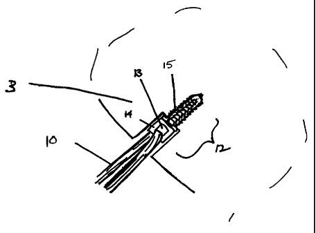
Figure 2 depicts shows a graft anchor assembly 12 of the instant invention
embedded in bone, for example in the cancellous layer of the femur 3. A tendon
graft 10
is looped through the aperture (see detailed drawing in Figure 3) in an anchor
assembly
12 with one or more free ends extending through other bone, for example,
through the
tibia 2.
Figure 3 depicts in more detail an anchor assembly 12 in operating position
embedded in the stepped bone tunnel. The autologous or artificial tendon graft
10 is
looped through aperture 13 in the head of the insertion element 14. The
stabilizing
element 15 is embedded in the bone tunnel, for example by screwing into the
stepped
tunnel. In another embodiment, the stabilizing element may be secured by means
of a
flange which opposes tension on the tendon graft, as shown in Figure 6. The
insertion
element 14 is held in the stabilizing element 15 for example by compression
fit, but could
also be held by other interference fit, e.g., screwing (though, preferably by
a thread) that
8
CA 02272251 2005-11-18
63266-52
requires twist, e.g~, of not more than 180 (so as to avoid twisting the
tendon) or by
ratcheting or by other attachment mechanism for holding one element in another
without
excessive twisting.
Figures 4a-d depict the anchor assembly in detail. Figure 4a depicts the
stabilizing element 15 which comprises ain elongated sleeve 19 containing
external
protrusions 16, for example, external threads. Stabilizing element 15 has a
cavity 17, for
example an elongated axial channel 17 extending at least partway from the
proximal end
of stabilizing element 15. For example, axial channel 17 could extend from the
proximal
to the distal end of stabilizing element 15. Stabilizing element has a flanged
head 18.
Stabilizing element 15 is comprised of a biocompatible material, for example,
implant
grade high density polyethylene, low density polyethylene (PE 6010 and PE
2030) and
polypropylene (13R9A and 23M2) all made by Rexene, Dallas, Texas or of a
bioabsorbable material, for example poly-l-lactide or such as a lactide-
glycolide
composition. It may also be comprised of a metal, such as surgical implant
grade steel.
Figure 4a also depicts insertion element 14. Insertion element 14 has an
aperture
13 containing head 21 for retaining a ligament replacement. Stem head 21 has
an
aperture 13 of a size suitable for receiving multiple strands of autologous
and/or artificial
tendon, but optimally for receiving two or more strands of semitendinosus
tendon. The
aperture 13 may have dimensions 0. 10 inches - 0.35 inches (height) by 0.05 -
0.30 inches
(width), and, preferably approximately 0.220 inches by 0. 160 inches.
Insertion element
14 has a stem 20, for example an elongated stem 20. The stem has protrusions
22
extending outwardly. Stem protrusions 22 may be inflexible. In the illustrated
embodiment, the diameter of stem 20 has a larger outer diameter than the inner
diameter
of axial channel 17, such that stabilizing element 15 is capable of holding
the insertion
element 14 by compression fit upon insertion of the insertion element 14 into
channel 17
of stabilizing element 15. The insertion element 14'can be tapped into the
stabilizing
element 15 with an emplacement device (not shown). Alternatively, the
insertion element
can be configured to be screwed, ratcheted or placed in other interference fit
within the
stabilizing element. The insertion element 14 is comprised of a biocompatible
material,
for examT',~ :mpiant grade high density polyethylene, low density polyethylene
(PE 6010
and PE 2030) and polypropylene (13R9A-and 23M2: all made by Rexene, Dallas,
Texas)
9
CA 02272251 2005-11-18
63266-52
or of a bioabsorbable material, for example poly-l-lactide
or such as a lactide-glycolide composition. It may also be
comprised of a metal, such as surgical implant grade steel.
Figure 4b depicts axial channel 17 which has a
non-cylindrical cross-section (not shown), optimally a
polygon such as a hexagon. Other non-cylindrical cross-
sections such as a square or pentagon or even oval
configurations are also envisioned. A non-cylindrical
cross-section of the axial channel 17 is designed such that
an emplacement device (not shown) such as a driver (not
shown) with a corresponding non-cylindrical diameter can be
inserted into an axial channel and turned such that the
external threads 16 of the stabilizing element 15 are
screwed into and grip the bone. One such driver is, e.g.,
an Allen wrench.
Figure 4c depicts insertion of the distal end of
an insertion element 14 into the axial channel 17 at the
proximal end of a stabilizing element 15. The diameter of
elongated stem 20 is slightly greater than the diameter of
the non-cylindrical axial channel 17 of the stabilizing
element. As a result as depicted in Figure 4d, an elongated
stem 20 of the insertion element 14 is held tightly in
stabilizing element 15, for example by compression fit into
stabilizing element 15 embedded in a stepped bone hole.
Figure 5a depicts an insertion element 510 that
can be pulled into the stabilizing element 15 (Figure 4).
As above, the insertion element 510 has an aperture 512
containing a head for retaining a ligament replacement and a
stem 514 with outwardly expanding protrusions. The diameter
of stem is greater than the diameter of axial channel such
that stabilizing element 515 is capable of holding the
insertion element by compression fit upon insertion of the
CA 02272251 2005-11-18
63266-52
insertion element into the channel of the stabilizing
element. Additionally, the insertion element 510 contains a
structure, e.g., aperture 516, suitable for receiving a
suture, a wire or other device that can be used to pull the
element 510 into the stabilizing element 515 instead of, or
in addition to, its being tapped into that element 515.
The aperture 516 or other such structure can be
located at any point on the insertion element 510 but is
preferably located at the distal end of the insertion
element. Thus, for example, in an embodiment in which the
stem of the insertion element is approximately 0.75 inches
long with a diameter of 0.16 inches, the aperture is located
0.05-0.20 inches from the end of the insertion element and
preferably 0.12 inches from the distal end.
The aperture 516 (or other such structure) is
sized sufficiently to accommodate a suture, wire or other
pulling device. Those of ordinary skill in the art will of
course appreciate that in lieu of an aperture, a slot, barb,
hook (as shown in Figures 5b and 5c) or any other structure
by which the insertion element can be pulled, can be
utilized.
An anchor assembly incorporating an insertion
element 510 of Figure 5a is generally implanted as described
above. In ACL reconstructive surgery, for example, a tunnel
is drilled at the anterior surface of the tibia and ending
with the cancellous region of the femur. The drill tunnel
preferably enters the femur at or near the isometric point
close to the anatomical ACL attachment site in accordance
with the prior art. The angle of the drill tunnel is in
accord with that practiced in the prior art for
semitendinosis-style ACL repair. A stepped hole is formed
by use of a stepped drill bit such that the ledge separating
11
CA 02272251 2005-11-18
63266-52
the wider and narrower diameter tunnels lies within the
cancellous portion of the femur, e.g., within at least 10 mm
to 70 mm within the femur of the posterior part of the
medical surface of the lateral condyle and, preferably,
approximately 45 mm of that surface.
Although the drill tunnel may terminate within the
cancellous portion of the femur, a guide wire or K-wire is
preferably used to fully penetrate the femur, leaving a
small exit aperture on the opposing surface on the femur.
The stabilizing element is then embedded in the drilled bone
tunnel, for example, by screwing it into the stepped tunnel.
At this point, the K-wire (which is preferably equipped with
an eyelet at its end) is used to thread a suture through the
skin, bone and through the channel of the stabilizing
element. The suture is then looped through the aperture,
hook, barb, or slot, or other such structure in the
insertion element. The insertion element is then pulled
into the stabilizing element using that suture. Those
skilled in the art will appreciate that a wire, hook or
other such apparatus can be used in place of the
aforementioned suture.
Figure 6 depicts yet another embodiment of the
invention, which employs two stabilizing elements and two
insertion elements. In this embodiment, a stepped tunnel is
drilled in the bone, beginning at the anterior surface of
the tibia 602 and ending within the cancellous region of the
femur 603, similar to the tunnel depicted in Figure lb. The
surgeon may elect initially to fully penetrate the femur 603
with a guide wire 626, leaving a small exit aperture 609 on
the opposing surface of the femur in accordance with the
prior art covering ACL reconstructive surgery.
12
CA 02272251 2005-11-18
63266-52
A first stabilizing element 615 is then inserted
in the femoral tunnel as has been described above.
Insertion elements 612 and 624 are joined by a length of
soft tissue 610, such as a tendon graft, and the first
insertion element 612 is inserted into the stabilizing
element 615, for example by pushing into the stabilizing
element 615, or by pulling with a suture, wire, or other
device 626 on a small aperture, slot, barb, or hook on the
insertion element 612. The second insertion element 624 is
pushed into the bone tunnel, and then the second stabilizing
element 628 is placed in the bone tunnel. In the preferred
embodiment depicted in Figure 6, the second stabilizing
element 628 comprises a flange 630 which limits the extent
to which the stabilizing element can be pulled into the bone
tunnel, e.g., by the tendon graft. This element is also
depicted in Figure 7 and is further discussed below. In
other embodiments, the second stabilizing element may be
secured by means of screw threads, an interference fit, or
other methods known in the art. Finally, the second
insertion element 624 is inserted into the second
stabilizing element 628. In the preferred embodiment
depicted in Figure 6, the second insertion element is
inserted into the second stabilizing element by pulling with
a suture, wire, or other device 632 on a small aperture,
slot, barb, or hook on the second insertion element 624.
In an embodiment for ACL replacement for an adult,
the first stabilizing element is typically of a length 20mm,
an outer diameter of 8mm, and an inner diameter of 3.5mm.
The first insertion element is typically of a length 40mm
and a diameter 8mm. If the insertion element is equipped
with an aperture whereby it may be pulled into the
stabilizing element, that aperture has a typical diameter of
lmm. The aperture for attachment of the tendon graft is
13
CA 02272251 2005-11-18
63266-52
typically about 5mm x 8mm. The length of the tendon graft
between the insertion elements is usually about 40mm. Those
skilled in the art will appreciate that the foregoing
dimensions are supplied merely by way of example and that
stabilization and insertion elements of sizes suited for
other bones, joints and grafts can be used as well.
The surgeon can adjust the tension on the tendon
graft by controlling the extent to which the insertion
elements are inserted into the stabilizing elements.
Insertion elements are typically designed so that full
strength hold of the insertion element in the stabilizing
element is obtained when the insertion element is inserted
at least halfway into the stabilizing element. Thus, the
depth of each insertion element is adjustable over a length
of 10mm for this preferred embodiment.
The second stabilizing element 628 of Figure 6 is
also illustrated in Figure 7. This element comprises an
elongated body 729, having a channel 731 for receiving an
insertion element. The stabilizing element also comprises a
flange 730, which prevents the element from being pulled
completely into the bone hole by tension on a graft attached
to an insertion element deployed in channel 731. The flange
730 may be perpendicular to the elongated body 729, or may
be at an oblique angle to the body 729, as depicted in
Figure 7. The flange 730 may also be contoured to
correspond to the shape of the outer surface of the bone in
which it is to be emplaced. The surgeon may also elect to
countersink the bone tunnel, so that the outer surface of
the emplaced flange 730 is flush with the surface of the
surrounding bone. In this embodiment, it may be desirable
for the flange 730 to be tapered, having a thicker cross-
section at the intersection of the flange 730 with the body
729 than at the outer edge of the flange 730.
14
CA 02272251 2005-11-18
63266-52
When this embodiment is used in ACL repair as
depicted in Figure 6, the second stabilizing element has a
typical length of 15mm, an outer diameter of 8mm, and an
inner diameter of 3.5mm. The flange has a typical outer
diameter of 12mm, and a typical thickness of lmm. The
second insertion element has a length 40mm and a diameter
8mm. If the second insertion element is equipped with an
aperture whereby it may be pulled into the stabilizing
element, that aperture has a typical diameter of imm. The
aperture for attachment of the tendon graft is typically
about 5mm x 8mm. Those skilled in the art will appreciate
that the foregoing dimensions are supplied merely by way of
example and that stabilization and insertion elements of
sizes suited for other bones, joints and grafts can be used
as well.
The second insertion element and second
stabilizing element, like the first elements, are comprised
of a biocompatible material, for example implant grade high
density polyethylene, low density polyethylene (PE 6010 and
PE 2030) and polypropylene (13R9A and 23M2) all made by
Rexene, Dallas, Texas or of a bioabsorbable material, for
example poly-l-lactide or such as a lactide-glycolide
composition. These elements may also be comprised of a
metal, such as surgical implant grade steel.
It will be apparent to those skilled in the art
that the above-described invention is not limited to
connecting the femur and tibia in an ACL reconstructive
procedure, but could also be practiced to support or repair
any bone or pair of bones with a length of soft tissue,
e.g., in the ankle or elbow region.
The invention further comprises methods for
CA 02272251 2005-11-18
63266-52
connecting at least two bone anchors, for example those
described above, with one or more lengths of graft material.
Figure 8 shows a graft 810 prepared according to a preferred
embodiment of this aspect. The graft 810 may be an
autologous tendon graft such as a length of semitendinosis
or gracillis tendon, or an artificial graft. The graft 810
has a filament 840 (such as a suture) attached to at least
one of its ends. In the preferred embodiment illustrated in
Figure 8, a suture 840 is whip-stitched to each end of the
graft.
The anchors may be connected with one or with
multiple grafts, in either a two-ply or four-ply
configuration. Some configurations according to the
invention are illustrated in Figures 9a-9f. In Figure 9a, a
single graft 910 is used to connect two anchors 942 and 944
in a two-ply configuration. A graft 910 prepared as
illustrated in Figure 8 is threaded through an aperture in
one anchor 944, and then folded so that the two ends of the
graft 910 can be tied and/or sewn to an aperture in the
other anchor 942 using the filament 940.
A related embodiment is illustrated in Figure 9b.
In this embodiment, the prepared graft 910 is threaded
through apertures in each of the two anchors 942 and 944.
The sutures 940 attached to the prepared graft are then
tied, or, preferably, sewn, to connect the ends of the graft
910. This embodiment is also a two-ply arrangement.
A four-ply connection between the anchors is
achieved using a single graft in the embodiment illustrated
in Figures 9c and 9d. A prepared graft 910 is first
threaded through one anchor 942, and folded to bring the
ends of the graft 910 into contact. These two ends are then
threaded through the other bone anchor 944. Figure 9c
16
CA 02272251 2005-11-18
63266-52
illustrates the configuration of the graft at this point in
its emplacement. The graft 910 is then folded in half
again, to bring the ends back to the first anchor 942, and
the ends are sewn and/or tied there with the attached
filaments 940, as illustrated in Figure 9d. Section A-A of
that figure shows the four plies of graft material 910 which
now connect the bone anchors.
Other embodiments which achieve a four-ply
connection between the anchors using multiple tendon grafts
are illustrated in Figures 9e and 9f. In the first of
these, one graft 910, prepared as shown in Figure 8, is
threaded through an aperture in a first anchor 944, and the
sutures 940 at the end of the graft are sewn and/or tied to
an aperture in a second anchor 942. A second graft 946 is
then passed through the aperture in the second anchor 942,
and sewn and/or tied to the aperture in the first anchor 944
with its attached sutures 948. In the second embodiment,
illustrated in Figure 9f, two grafts 910 and 946 are
threaded through an aperture in the first anchor 944, and
these two grafts are both sewn and/or tied to the aperture
in the second anchor 942 with their attached sutures 940 and
948.
It will be apparent to one skilled in the art of
ligament reconstruction that each of the embodiments
illustrated in Figures 9a-9f has different strengths, and
that the preferred configuration for a particular use of the
invention will depend on the ligament being replaced, the
location and type of the bone anchors, and on whether the
graft is attached to the anchors before or after they are
affixed to the bone.
Described above are apparatus and methods meeting
the objects set forth above. Those skilled in the art will
17
CA 02272251 2005-11-18
63266-52
appreciate that the illustrated embodiments are shown and
described by way of example only, and that other methods and
apparatus incorporation modifications therein fall within
the scope of the invention. For example, in addition to ACL
reconstruction, the invention can be beneficially applied in
connection with other soft tissue-to-bone attachments using
bone tunnels, such as (by way of non-limiting example)
repair of ligaments and tendons in other joints such as the
elbow and ankle. In view of the foregoing, what we claim
is:
18