Note: Descriptions are shown in the official language in which they were submitted.
CA 02272289 2007-07-31
72648-13
~
DESCRIPTION
Hvbrid One-Step ImmunochromatograDh.ic
Device and Method of Use
Backcrround of the Invention
This inven-tion relates to immunological methods and
devices for detecting analytes in biological samples.
Numerous approaches have been developed for detection
of a given analyte in a biological sample. Typical af
these methods are the so called "lateral flow" and "flow-
through" devices and methods. The flow-through device
generally uses a porous material with a reagent-Containing
matrix layered thereon or incorporated therein. Test
sample is applied to and flows through the porous
material, and analyte in the sample reacts with the
reagent(s) to produce a deteGtable signal on the porous
material. These devices are generally encased in a
nlastic housing or casing with calibrations to aid in the
detection of the particular analyte.
Lateral flow assays also utilize a porous membrane for
performing analyte detection. Instead of drawing the
sample through the membrane perpendicularly, the sample is
permitted to flow latera3.ly from an application zone to a
reaction zone on the membrane surface_ The capture
reagent is present in the reaction zone, and the captured
CA 02272289 1999-05-18
WO 98/22800 PCT/US97/21245
2
analyte can be detected by a variety of protocols,
including direct visualization of -visible moieties
associated with the captured analyte.
One-step lateral flow assays permit a user to add a
sample to a sample application region and obtain a
positive or negative signal signaling the presence or
absence of the test analyte in the sample.
One-step lateral flow devices contain a sample
application region to which the sample is applied. The
sample application region is in lateral flow contact with
the porous carrier material of the analyte detection
region. During lateral flow, the sample is brought into
contact with a mobile indicator reagent in a discrete zone
of the analyte detection region. The indicator reagent
contains both a binding moiety which specifically binds to
the target analyte and an indicator moiety, which is most
often a chromophore label. Target analyte molecules
moving in the lateral flow bind to the indicator reagent
and are ultimately immobilized in the capture zone,
usually by binding to a second reagent which binds
specifically to the analyte or to the analyte-indicator
reagent complex. The position of the immobilized
indicator reagent gives rise to a positive signal.
Additional signals may include a negative reaction
indicator, a test complete indicator, and a positive
control indicator.
One-step immunochromatographic devices containing the
indicator reagent in a discrete zone of the lateral flow
porous material, e.cr., at a discrete site on the test
strip,__have been described.
For example, Deutsch et al. describe a quantitative
chromatographic test strip device in U.S. Patent Nos.
4,094,647, 4,235,601 and 4,361,537. The device comprises
a strip of material capable of transporting a solution by
capillary action, i.e., wicking. Different areas or zones
in the strip contain the reagents needed to produce a
detectable signal as the analyte is transported to or
CA 02272289 1999-05-18
WO 98/22800 PCT/US97/21245
3
through such zones. A diffusible label which can bind to
the test analyte may be located in a discrete region of
the strip. The device is suited for both chemical assays
and binding assays which aria typified by the binding
reaction between an antigen and its complementary
antibody.
In addition, British App:lication No. 2,204,398 de-
scribes a lateral flow device: wherein sample applied to
the device picks up labeled reagent located at a discrete
site on the porous carrier of the strip and permeates into
a detection zone. .The indicat.or labels include gold sols
and colored particles.
Alternatively, devices containing the mobile indicator
reagent in a separate porous material or pad have been
disclosed.
For instance, European Publication No. 323,605
discloses an assay device using chromatographic material
wherein the test sample can travel from one end to the
other by capillary action. The chromatographic material
contains an immobilized capture reagent capable of binding
to the analyte. The application pad which receives the
test sample also contains a diffusible indicator reagent
capable of migrating from the application pad to the
chromatographic material. The indicator reagent is
capable of binding to the analyte. The binding of the
indicator reagent-analyte complex results in a detectable
signal at the capture situs.
PCT application No. WO 94/06013 also describes a
lateral flow assay in which the indicator reagent has been
placed in a separate indicator reagent region or pad
(referred to as "the third liquid permeable material") .
The sample is added to a separate sample application pad,
passes through a second permeable material, and mobilizes
the indicator reagent located in the third liquid
permeable material. The sample then enters the wicking
material containing the capture zone.
CA 02272289 2007-07-31
72648-13
4
Pdtent application WO 92/01226 describes a lateral
flow device in which the labeled specific binding reagent
is retained in the dry state either in a zone on the
carrier material or in a separate porous body through
which the sample passes en route to the porous carrier
matezial of the test strip.
U.S. Patent No. 5,712,172 and its
corresponding PCT application 96/04748 also describe
lateral flow assay devices in which the labeled reagent
for the analyte is located in a discrete zone of the
porous carrier material of the analyte detection region.
Other variations of test strip assays are disclosed in
U.S. Patent Nos. 4,298,688, 4,517,288 and 4,740,468, which
describe sheet-like diagnostic devices comprising one or
several strips, arranged behind one another, having zones
situated one behind another. Each zone is readily acCes-
sible from above and below for the addition of reagents.
Such devices.can guantitatively determine the amount of an
analyte_
Procedures using chrornogenic and fluorescent dyes as
labels in biological assay proceduze:s are also known.
Typical assay protocols call for direct or indirect
binding of a dye label to an analyte or analyte analog in
a biological sample, where the presence or absence of the
dye at a particular stage of the assay can be determined
visually and related to the amount of analyte initially
grtsent in the sample. A wide variety of specific assay
vrotocols exist.
A number of those assays utilize naturally colored or
dyed particles as a label, where the particles are bound
to an antibody or other specific binding substance.
suggested particles include dyed latex beads, dye imbibed
liposomes, erythrocytes, metal sols, and the like. The
colored particle in such complexes can serve as a visible
marker, where separation, capture, or aggregation of the
particles is mediated through binding of the antibody or
other specific binding substance. The amount of label
CA 02272289 1999-05-18
WO 98/22800 PCT/US97/21245
thus segregated in a particular assay step is related to
the amount of analyte initially present in the sample.
For example, U.S. Patent No. 4,943,522 describes a
solid phase lateral flow assay using erythrocytes as a
5 label. U.S. Patent No. 4,863,875 describes compositions
comprising at least ten dye molecules or monomers
covalently attached to an antibody through an isocyanate
group on the dye. U.S. Patent No. 4,703,017 describes a
solid phase assay device which relies on specific binding
of a ligand-label conjugate or.i a solid support, where the
label is disclosed as a particle, such as a liposome, or
polymer microcapsule. U.S. Patent No. 4,608,246 describes
assays for typing blood whic:h employ erythrocytes as a
labeling agent. U.S. Patent No. 4,452,886 describes the
covalent attachment of phot:on absorbing or emitting
polymers to proteins, such as antibodies and antigens.
U.S. Patent No. 4,373,932 describes labeling of a ligand
with an aqueous dispersion of a hydrophobic dye or
pigment, or a polymer nuclei coated with such a dye or
pigment. U.S. Patent No. 4,313,734 describes methods of
detecting sample analytes by the determination of the
metallic label content in the sample. U.S. Patent No.
4,169,138 describes immunoassays which employ visible
particles including undyed microorganisms, bound to
polymers which may be of microbial origin.
Other lateral flow protocols include U.S. Patent
4,943,522 directed to a lateral flow device which relies
on a nonbibulous support to conduct liquids from one
portion of the device to another. PCT Publication WO
92/12428, which is related to the above patent, represents
an improvement on that method and device wherein
nonbibulous lateral flow is used to conduct visible
moieties, especially labeled particles, e.g., dyed latex,
red blood cells or liposome,s capable of reacting with
analyte or a competitor thereto into a capture zone for
detection, using a bibulous support made nonbibulous by
treatment with a blocking agent. The result is a one-step
CA 02272289 1999-05-18
WO 98/22800 PCT/US97/21245
6
assay which can be conducted in a very short period of
time (typically, within 60 seconds), and wherein the
readout is usually available instantaneously upon the
sample contacting a capture zone.
These one-step assays are complex devices containing
a number of immunoassay reagents. Because the ability to
manipulate the sample is restricted, it is desirable to
develop other design variations that increase the range of
sensitivity of the assay without increasing either the
time necessary to perform the assay or the number of false
positive results.
None of the references described herein is admitted to
be prior art.
Summary of the Invention
This invention relates to an immunoassay device with
an increased range of assay sensitivity. Changes in the
concentration of labeling reagents, buffer composition of
the labeling reagents, and arrangement of the labeling
reagents can alter the sensitivity of the assay, the
occurrence of false positive reactions, and the time
required to obtain clearance of unbound indicator labeling
reagents through the device.
The immunoassay devices of this invention increase the
range of assay sensitivity without increasing the time
needed to perform the assay or the occurrence of false
positive reactions. The increased range of assay
sensitivity is accomplished by providing at least two
indicator labeling reagents which have different lateral
flow characteristics.
The lateral flow characteristics of a given indicator
labeling reagent may be altered, for example, by placing
the indicator labeling reagent in two regions of the
lateral flow device which have different lateral flow
rates, or by altering the composition of the indicator
labeling reagent solution applied to the lateral flow
device. In addition, both the location and the
CA 02272289 1999-05-18
WO 98/22800 PCT/US97/21245
7
composition of the two solutions containing the indicator
labeling reagent may be altered.
Preferably the device contains two indicator labeling
reagents differing in their lateral flow properties, i.e.,
a first indicator labeling reagent and a second indicator
labeling reagent. Although the labeling reagents are
designated as the first, second, . . . nth indicator
labeling reagents to denote the different lateral flow
properties of the first through nth indicator labeling
reagent, the actual analyte binding molecule of the
indicator labeling reagents may be the same or different,
as long as the lateral flow properties of the indicator
labeling reagents differ.
For instance, the lateral flow properties of a given
indicator labeling reagent may be altered by placing an
indicator labeling reagent for the analyte in two distinct
areas of the device--both in a discrete zone of the
lateral flow porous carrier material of the analyte
detection region, and in a separate porous region through
which the sample must flow to the capture zone. In this
example the indicator labeling reagent in the discrete
zone of the lateral flow porous carrier may be termed the
first indicator labeling reagent, while the indicator
labeling reagent located in the separate porous zone may
be designated as the second inidicator labeling reagent, or
vice versa.
Alternatively, or in addition, two solutions
containing an indicator label:i.ng reagent may be applied to
different zones of the device. The composition of the
indicator labeling solution naay be altered, for example,
= by altering the concentration of solutes in the solution.
Different solutions of indicator labeling reagent
containing different concen'tration of solutes can be
applied to different zones of the device and then dried,
resulting in changes in the viscosity of the sample as it
passes through these different zones of the device, or
changes in the rehydration rate of the indicator labeling
CA 02272289 1999-05-18
WO 98/22800 PCT/US97/21245
8
reagent. The differences in the viscosity of the sample
solution as it laterally flows through these zones, or in
the rehydration rate of the indicator labeling reagent,
will impart different lateral flow properties as the
sample flows through these two zones. These zones may be
on the same porous region of the device, or on separate
porous regions.
Previously described one-step devices contained the
indicator labeling reagent for the analyte in only one of
two locations--either in the lateral flow porous carrier
material of the test strip or in a separate porous
material, for example, a pad of porous material.
Moreover, previously described devices did not contain two
or more different zones of indicator labeling reagents
containing different compositions of dried solutes.
One-step devices which contain the indicator labeling
reagent located in a discrete region in the lateral flow
porous material, e.g., in a label zone on the test strip,
have the advantage that the indicator labeling reagent is
rehydrated, or mobilized quickly, leading to a quicker
clearance time. That is, the time that it takes for
unbound indicator labeling reagent to pass through the
capture zone is shorter. However, because the analyte
indicator labeling reagent complex has less time to
incubate with and bind to the indicator capture reagent in
the capture zone, and because the time for the indicator
labeling reagent to bind to the analyte is shorter, these
types of devices have a lower range of sensitivity than
devices containing the indicator reagent in a separate
labeling reagent region, or labeling pad. Moreover,
increasing the level of indicator labeling reagent
contained in the porous carrier in order to increase
sensitivity increases the maximum concentration of
indicator labeling reagent passing through the capture
zone, which increases the possible number of false
positive results.
CA 02272289 2007-07-31
72648-13
9
On the other hand, placement of the indicator
labeling reagent in a separate region, e.g., a porous pad,
permits a more sustained release of indicator labeling
reagent over a longer period of time. This results in a
longer time period for incubation of the indicator labeling
reagent with the analyte and a longer time period for
movement of both bound and unbound indicator labeling
reagent to pass the capture zone. This in turn gives rise
to greater sensitivity, but also results in slower clearance
times. Increasing the amount of indicator labeling reagent
in the separate pad can further increase the low-end
sensitivity, i.e., increase the ability to detect low
concentrations of analyte, but results in even greater
clearance times. Thus, rather than increase the amount of
indicator labeling reagent in either a separate porous
indicator labeling reagent region, or in a discrete zone of
the material of the lateral flow porous carrier of the
analyte detection region, the devices of this invention
contain at least two zones of indicator labeling reagent
having different lateral flow properties.
Thus, in one aspect, this invention describes an
immunochromatographic assay device for detection of the
presence or absence of an analyte in a liquid sample,
wherein said immunochromatographic assay device comprises:
(a) a sample receiving region comprising a porous material
which conducts lateral flow of a liquid sample, in lateral
flow contact with (b) an analyte detection region comprising
a porous material which conducts lateral flow of said liquid
sample, wherein said analyte detection region comprises an
immobile indicator capture reagent at a discrete indicator
capture reagent situs, wherein said immunochromatographic
device also comprises: a first indicator labeling reagent
zone comprising a first mobile indicator labeling reagent,
CA 02272289 2007-07-31
72648-13
and a second indicator labeling reagent zone comprising a
second mobile indicator labeling reagent wherein the lateral
flow characteristics of the indicator labeling reagent in
the first zone differ from the lateral flow characteristics
5 of the indicator labeling reagent in the second zone,
wherein said first mobile indicator labeling reagent forms a
complex binding with said analyte, and wherein said second
mobile indicator labeling reagent forms a complex binding
with said analyte, and wherein said zones are in lateral
10 flow contact with said sample receiving region and said
analyte detection region, and wherein said liquid sample
laterally flows from said sample receiving region towards
said analyte detection region, and mixes with said first and
second indicator labeling reagents to move said first and
second indicator labeling reagents towards said analyte
detection region, wherein said immobile indicator capture
reagent forms a complex comprising said analyte, said first
or second mobile indicator labeling reagent and said
immobile indicator capture reagent.
In another aspect, this invention describes an
immunochromatographic assay device for detection of the
presence or absence of an analyte in a liquid sample,
wherein said immunochromatographic assay device comprises:
(a) a separate sample receiving region comprising a porous
material which conducts lateral flow of a liquid sample,
wherein said sample receiving region comprises a first
mobile indicator labeling reagent at a discrete labeling
situs, wherein said first mobile indicator labeling reagent
forms a complex binding with said analyte, wherein said
sample receiving region is in lateral flow contact with (b)
a separate analyte detection region comprising a porous
material which conducts lateral flow of said liquid sample,
wherein said separate analyte detection region comprises a
CA 02272289 2007-07-31
72648-13
l0a
second mobile indicator labeling reagent at a discrete
labeling situs, wherein said second mobile indicator
labeling reagent forms a complex binding with said analyte,
an immobile indicator capture reagent at a discrete capture
situs, wherein said immobile indicator capture reagent forms
a complex comprising said analyte, said first or second
mobile indicator labeling reagent, and said immobile
indicator capture reagent, wherein the lateral flow
characteristics of the first mobile indicator labeling
reagent in the sample receiving region differ from the
lateral flow characteristics of the second mobile indicator
labeling reagent in the analyte detection region wherein
said analyte detection region is in lateral flow contact
with (c) a separate end flow region comprising a porous
material which conducts lateral flow of said liquid sample
and capable of absorbing excess liquid sample, wherein said
liquid sample laterally flows from said sample receiving
region towards said end flow region, and mixes with said
first and second mobile indicator labeling reagents to move
said labeling reagents towards said end flow region.
In a first preferred embodiment, the devices of
this invention contain indicator labeling reagent in both a
separate porous material and located in a discrete region of
the lateral flow porous carrier of the analyte detection
region. This results in an increased range of sensitivity
without giving rise to an increase in the number of false
positives, or increasing the clearance time.
Thus, in a first preferred embodiment, the
immunoassay devices of this invention may contain a first
area of placement of the indicator labeling reagent in a
separate porous material, e.g., a pad, which is contiguous
with the sample receiving region and in direct contact with
the lateral flow porous material of the analyte detection
CA 02272289 2007-07-31
72648-13
10b
region (Fig. 1). The second area of placement of the
indicator labeling reagent is in a discrete zone in the
porous material of the analyte detection region. (Fig. 1).
The indicator labeling reagent in the discrete zone is
quickly mobilized when contacted by the lateral flowing
sample fluid, thereby creating an initial high concentration
of indicator labeling reagent passing through the capture
zone. In addition, the placement of indicator labeling
reagent in the separate porous material, i.e., a separate
labeling reagent region, allows for sustained release of
indicator labeling reagent as sample fluid moves through the
separate labeling reagent
CA 02272289 1999-05-18
WO 98/22800 PCT/US97/21245
11
region into the lateral flow porous material region by
capillary action. The sustained release of indicator
labeling reagent for the analyte facilitates low-end assay
sensitivity by increasing the time of incubation of the
indicator labeling reagent with the analyte, and
increasing the time of incubation of the bound indicator
labeling reagent with the indicator capture reagent in the
capture zone. This results in an increase in the amount
of bound label to pass through the capture zone without
increasing the maximum concentration of label to pass
through the capture zone (and the number of false positive
results) and without increasing the clearance time
compared to an assay device in which the indicator
labeling reagent is placed only in a separate labeling
reagent region.
In a second preferred embodiment the device contains
at least two zones to which dlifferent indicator labeling
reagent solutions have been. applied. The different
indicator labeling reagent solutions differ in the
concentration of solutes. The indicator labeling reagent
in the two solutions may bind to the same or different
epitope of the analyte. If a solution of indicator
labeling reagent is applied to the device in a solution
having a low solute concentration, i.e., a low
concentration of sugars such as sucrose, the indicator
labeling reagent will be mobilized quickly, leading to a
quicker clearance time but a shorter time for interaction
of the indicator labeling reagent with the analyte.
On the other hand, if the indicator labeling reagent
is applied to the device in a solution having a high
= solute concentration, the indicator labeling reagent will
be mobilized more slowly, leading to a slower clearance
time but greater sensitivity due to greater time for the
indicator labeling reagent to incubate and bind to the
analyte.
Thus, in a second preferred embodiment, the
immunoassay devices of this irivention may contain a first
CA 02272289 1999-05-18
WO 98/22800 PCT/US97/21245
12
zone containing indicator labeling reagent which has been
applied in a solution containing a low solute
concentration. The second area of placement contains
indicator labeling reagent which has been applied in a
solution containing a high solute concentration.
The indicator reagent in the low solute zone is
quickly rehydrated, or mobilized when contacted by the
lateral flowing sample fluid, thereby creating an initial
high concentration of indicator labeling reagent passing
through the capture zone. In addition, the placement of
indicator labeling reagent in the second area of high
solute concentration allows for sustained release of
indicator reagent, as sample fluid moves through this
region, as the viscosity of the sample increases and the
rehydration rate decreases. The sustained release of
indicator reagent for the analyte facilitates low-end
assay sensitivity by increasing both the time of
incubation of the indicator labeling reagent with the
analyte and the time of incubation of the bound indicator
labeling reagent with the indicator capture reagent in the
capture zone. This results in an increase in the amount
of bound label to pass through the capture zone without
increasing the maximum concentration of label to pass
through the capture zone (and the number of false positive
results) and without increasing the clearance time
compared to an assay device in which the indicator reagent
is placed only in a separate labeling reagent region.
Preferably where the first indicator labeling reagent
and the second indicator labeling reagent are placed in
separate porous regions of the device, the concentration
of indicator labeling reagent in the separate labeling
reagent region is lower than the concentration in the
discrete zone of the analyte detection region. Preferably
where the first indicator labeling reagent area and the
second indicator labeling reagent area differ in solute
concentration, the concentration of indicator labeling
reagent which first comes into lateral flow contact with
CA 02272289 2007-07-31
72648-13
13
the sample will be lower than the concentration of indicator
labeling reagent which subsequently comes into lateral flow
contact with the sample.
Also, in this embodiment, preferably lateral flow
contact of the sample with the first indicator labeling
reagent in the separate labeling reagent region results in
sustained release of the first indicator labeling reagent,
while lateral flow contact of the sample with the second
indicator labeling reagent in the labeling reagent zone of
the analyte detection region results in quick release of the
second indicator labeling reagent.
This device provides a simple, convenient assay
method, with increased sensitivity and no increase in
clearance time. This device is useful for detecting various
analytes in a liquid sample.
Thus according to the present invention, there is
provided a method to determine the presence or absence of
analyte in a sample, which method comprises applying said
sample to the sample receiving region of the device
described herein so as to permit said sample to flow through
the analyte detection region and into the end flow region,
and detecting the presence or absence of analyte in the
analyte detection region at the discrete capture reagent
situs containing the immobile indicator capture reagent
which comprises the analyte, the first or second mobile
indicator labeling forms a complex reagent, and the immobile
indicator capture reagent.
According to the present invention, there is also
provided a method to determine the presence or absence of
analyte in a sample, which method comprises applying said
sample to the sample receiving region of the device
CA 02272289 2007-07-31
72648-13
13a
described herein so as to permit said sample to flow through
the analyte detection region and into the end flow region,
and detecting the presence or absence of analyte in the
analyte detection region at the discrete capture situs
containing the mobile indicator capture reagent, wherein, in
the presence of said analyte, said indicator capture reagent
forms a complex comprising the analyte, the first or second
mobile indicator labeling reagent, and the immobile
indicator capture reagent, and detecting the presence or
absence of a control signal in the analyte detection region
at the discrete control situs containing the control capture
reagent capable of binding the control labeling reagent.
Taking advantage of the test device of the present
method, the device can be utilized with a method for
detection of analytes directly from a biological sample,
such as urine, blood, sputum, or material extracted from
swabs or feces. In particular, the invention can be used to
detect the presence or absence of human chorionic
gonadotropin ("hCG") in urine. This detection is useful, in
determining a positive or negative pregnancy in women.
Alternatively, the invention can be used to detect the
presence or absence of an antigen from streptococcus, for
example, streptococcus pyogenes Group A, in material
extracted from swabs of throat tissue.
In a first aspect of this invention, the separate
sample receiving region is in contact with a separate
labeling reagent region which is also made of a porous
material which conducts liquid flow of the sample. The
separate labeling reagent region is in contact with a
separate analyte detection region. Lateral flow of the
liquid sample will continue from the sample receiving region
CA 02272289 2007-07-31
72648-13
13b
to the separate labeling reagent region to the analyte
detection region. The analyte detection region contains a
porous material which conducts lateral flow of
CA 02272289 1999-05-18
WO 98/22800 PCT/US97/21245
14
the liquid sample. Preferably, the analyte detection
region contains a discrete zone containing a second
indicator labeling reagent which binds specifically to the
analyte. The discrete zone and/or the separate labeling
reagent region may also contain a mobile control labeling
reagent.
The analyte detection zone also contains a capture
zone. The capture zone is a discrete zone containing an
immobile indicator capture reagent which can bind to the
analyte or to the analyte-indicator labeling reagent
complex. The capture zone may also contain a second
capture reagent, i.e., a control capture reagent, which
binds to the control labeling reagent.
Alternatively in a second aspect, the sample receiving
region may be in direct contact with the analyte detection
region which is in direct contact with a separate labeling
reagent region (Fig. 2). In this configuration, the
analyte detection region will be split into two portions.
The first portion will contain the situs or zone for the
indicator labeling reagent for the analyte, and the zone
containing the control labeling reagent. The second
portion of the analyte detection region will contain
discrete zones containing the indicator capture reagent
for the analyte and the control capture reagent.
In still another alternative embodiment, the sample
receiving region may either contain a first indicator
labeling reagent for the analyte (Fig. 3), or be
positioned above the separate labeling reagent region
containing a first indicator labeling reagent, in direct
flow contact with the separate labeling reagent region.
Alternatively, another separate porous region may be
placed below the sample receiving region and above the
separate labeling reagent region, to help direct flow of
the sample to the separate labeling reagent region.
The analyte detection region is also in lateral flow
contact with the end flow region. The end flow region
contains a porous material which conducts lateral flow of
CA 02272289 1999-05-18
WO 98/22800 PCT/US97/21245
the liquid sample. It is capable of absorbing excess
liquid sample.
In the above aspect, the first indicator labeling
reagent for the analyte (which is present in the separate
5 labeling reagent region) and t:he second indicator labeling
reagent (which is present in the discrete zone of the
analyte detection region) are capable of forming a complex
with the analyte. The analyte binding molecule can be the
same or different in the first: indicator labeling reagent
10 and the second indicator labe:Ling reagent.
The control labeling reagent ismobile but does not
form a complex with either the analyte or the indicator
capture reagent. The indicator capture reagent is capable
of binding the analyte-indicator labeling reagent(s)
15 complex, either by recognizing a binding site on the
analyte or on the analyte-indicator reagent(s) complex.
The control capture reagent is capable of binding the
control labeling reagent.
In addition, preferably the porous materials in the
above aspect are laminated with one continuous or separate
semi-rigid material of at least 0.001 inches thick. The
laminate covers the back only and provides adequate
mechanical strength to the device, i.e., it provides
support and strength characteristics to the porous
material and overall device.
In a second aspect, the material used for the separate
labeling reagent region enables the sustained release of
the indicator labeling reagent, while the material used
for the analyte detection region provides for quick
release of the indicator labe:ling reagent.
Def init ions
The term "analytell as used herein refers to a compound
or composition to be detected or measured in the test
sample. The analyte will have at least one epitope that
an antibody or an immunological reactive fragment thereof
can recognize. Analyte can include any antigenic sub-
CA 02272289 1999-05-18
WO 98/22800 PCTIUS97/21245
16
stances, haptens, antibodies and combinations thereof.
The analyte of interest in an assay can be, for example,
a protein, a peptide, an amino acid, a nucleic acid, a
hormone, a steroid, a vitamin, a pathogenic microorganism
for which polyclonal and/or monoclonal antibodies can be
produced, a natural or synthetic chemical substance, a
contaminant, a drug including those administered for
therapeutic purposes as well as those administered for
illicit purposes, and metabolites of or antibodies to any
of the above substances. One preferred example of a
hormone suitable for detection is human chorionic gonado-
tropin ("hCG"). Additional examples of preferred analytes
are the pathogenic organisms streptococcus group A or B,
or H. pylori. Other examples of preferred analytes are
human antibodies against infectious agents such as HIV
(used in diagnosis of AIDS), EBV (used in diagnosis of
mononucleosis), or hepatitis virus, etc. Still other
examples of preferred analytes are human proteins such as
myoglobin, creatine kinase-MB, troponin-I, troponin-T or
hemoglobin, etc.
The term "sample" as used herein refers to any biolog-
ical sample that could contain an analyte for detection.
Preferably the biological sample is in liquid form or can
be changed into a liquid form. Preferably, the sample is
a urine sample, or material extracted from a swab of
throat tissue.
As used herein, the term "sample receiving region"
means the portion of the assay device which is in direct
contact with the liquid sample, i.e., it receives the
sample to be tested for the analyte in question. The
liquid sample can then migrate, through lateral flow, from
the sample receiving region towards the end flow region.
Preferably the sample receiving region is the edge of the
assay device. The sample receiving region is in lateral
flow contact with either the separate labeling reagent
region or the analyte detection region. This could either
be an overlap or end-to-end connection. The sample
CA 02272289 1999-05-18
WO 98/22800 PCT/US97l21245
17
receiving region may be intpregnated with buffer to
neutralize reagents in the saniple during the lateral flow
immunoassay.
The analyte in the sample must be capable of
migrating, through lateral flow, with the liquid sample.
The sample receiving region is made of porous material,
preferably porous paper.
As used herein, the term "porous material" refers to
any material capable of providing lateral flow. This
would include material such as nitrocellulose, nitrocellu-
lose blends with polyester or cellulose, untreated paper,
porous paper, rayon, glass fiber, acrylonitrile copolymer
or nylon. One skilled in the art will be aware of other
porous materials that allow lateral flow. The term
"lateral flow" refers to liquid flow in which all of the
dissolved of dispersed components of the liquid are
carried at substantially equal rates and with relatively
unimpaired flow laterally through the material, as opposed
to preferential retention of one or more components as
would occur, e.g., in materials capable of adsorbing or
imbibing one or more components.
The term "mobile" as referred to herein means dif-
fusively or non-diffusively attached, or impregnated. The
reagents which are mobile are capable of dispersing with
the liquid sample upon rehyciration and carried by the
liquid sample in the lateral flow. The term "immobile" as
used herein refers to reagents which are attached to the
support such that lateral flow of the liquid sample does
not affect the placement of the immobile particle in the
discrete region of the porous material. Such attachment
can be through covalent, ionic or hydrophobic means.
Those skilled in the art will be aware of means of
attachment to immobilize various particles.
The term "labeling reagent" refers to a suitable
reagent labeled with a chromogenic particulate such as
colored latex, colloidal gold, selenium or the like. The
CA 02272289 1999-05-18
WO 98/22800 PCT/US97/21245
18
term "labeling reagent" may refer either to an indicator
labeling reagent or a control labeling reagent.
The term "indicator labeling reagent" refers to any
particle, protein or molecule which recognizes or binds to
the analyte in question, and which is conjugated or
attached to a substance or particle capable of producing
a signal that is detectable by visual or instrumental
means. The attachment to the substance or particle
capable of producing a signal may be chemical, covalent or
noncovalent, ionic or non-ionic. Such labels producing a
signal would include chromogens, catalysts, fluorescent
compounds, colloidal metallic and nonmetallic particles,
dye particles, enzymes or substrates, organic polymers,
latex particles, liposomes with signal producing
substances and the like. The particle or molecule recog-
nizing the analyte can be either natural or non-natural,
preferable monoclonal or polyclonal antibody.
Indicator labeling reagents may be, for example, a
monoclonal or polyclonal antibody to the O-epitope of hCG,
or a polyclonal or monoclonal antibody to the carbohydrate
antigen of Streptococcus Group A. It is well known in the
art that the carbohydrate antigen of Group A Streptococcus
contains a repeated epitope. Thus, a sandwich complex can
be formed even if the indicator capture reagent and the
indicator labeling reagent each contain an antibody to the
same epitope of Strep A.
The indicator labeling.reagent may be bound to a label
such as colored latex or gold sol particles. One of
ordinary skill in the art will also appreciate that the
label can be the same on the indicator labeling reagent
and the control labeling reagent.
The mobile control labeling reagent is a particle or
molecule which does not bind to the indicator capture
reagent and is conjugated to a substance or particle
capable of producing a signal. Preferably the control
labeling reagent is BSA bound to a label such as colored
latex or gold sol particles.
CA 02272289 1999-05-18
WO 98/22800 PCTIUS97/21245
19
Alternatively, the control labeling reagent may be the
same reagent as the indicator labeling reagent. In that
embodiment, the "control capture reagent" is a reagent
capable of binding the control labeling reagent but which
does not bind to the analyte or the indicator labeling
reagent-analyte complex. For instance, the control
labeling reagent and indicator labeling reagent may be a
rabbit anti-Strep A antibody linked to a label such as
gold sol particles. In that embodiment, the capture
reagent for the "control labeling reagent" also binds to
the "indicator labeling reagerit", but it does not bind the
analyte. For instance, the control capture reagent for
the positive control signal may be anti-rabbit T-globulin
antibody, while the indicator capture reagent of the
analyte signal is an antibody to the Strep A antigen.
A "labeling particle" is a particle which contains a
substance capable of producinq a signal that is detectable
by visual or instrumental means, e.g., a dye particle or
latex particle containing a dye. Preferably the labeling
particle is colored latex particles or gold sol.
The term "separate labeling reagent region" refers to
a region which contains indicator labeling reagent. The
separate labeling reagent region may also contain control
labeling reagent. The separate labeling reagent region is
preferably made of a mixture of cellulose and polyester,
or other porous material.
The term "indicator captiure reagent" as used herein
refers to any particle or molecule which recognizes or
binds the analyte in question. The indicator capture
reagent is capable of formincl a binding complex with the
complex formed by the binding of the analyte to the
indicator labeling reagent(.s). The indicator capture
reagent is immobilized to the porous material of the
analyte detection region.
The capture reagent is immobile, i.e., is not affected
by the lateral flow of the liquid sample due to the
immobilization to the porous material. The particle of
CA 02272289 1999-05-18
WO 98/22800 PCT/US97/21245
molecule of the indicator capture reagent can be natural,
or non-natural, i.e., synthetic. Once the indicator
capture reagent binds the analyte-indicator labeling
reagent(s) complex it prevents the analyte-labeling
5 reagent from continuing with the lateral flow of the
liquid sample.
The term "control capture reagent" as used herein
refers to any particle or molecule which is capable of
binding the control labeling reagent which does not
10 recognize or bind the analyte of question in the sample.
For example, the control labeling reagent may be BSA
conjugated to a label, such as colored latex, gold sol
particles, or other labels known in the art.
The term "capture reagent" may refer to either the
15 indicator capture reagent or the control capture reagent.
The capture reagent may be applied to the porous material
in any geometrical shape desired.
In one preferred embodiment, the control capture
reagent would be a particle or molecule which recognizes
20 or binds the BSA conjugated to the labeling particle.
Preferably, the control capture reagent would be a
monoclonal or polyclonal antibody which recognizes BSA.
Just as the indicator capture reagent is immobilized in a
discrete situs on the porous material of the analyte
detection region, the control capture reagent is also
immobilized in a discrete situs on the porous material of
the analyte detection region. Once it binds the control
labeling reagent it immobilizes the control labeling
reagent and prevents it from continuing lateral flow with
the liquid sample. Binding of the immobilized capture
control reagent to the control labeling reagent results in
the formation of a positive control signal, which serves
as an internal control that the assay was performed
properly.
The term "clearance time" refers to the time that it
takes for a sufficient amount of unbound indicator
labeling reagent to flow through the capture zone so that
CA 02272289 1999-05-18
WO 98/22800 PCTIUS97/21245
21
the background is sufficiently reduced compared to the
capture zone band intensities to permit an accurate
reading of the positive and negative results. Unbound
indicator labeling reagent in the capture zone may lead to
higher background and false :positives. The clearance
time reflects the time that it: will take for the assay to
be completed.
The term "analyte detection region" as used herein
refers to the portion of the assay device which is in
lateral flow contact with the end flow region, and either
the porous material of the saniple receiving region or the
porous material of the separate labeling reagent region.
The contact can be an overlap or end-to-end connection.
The analyte in the sample must be capable of migrating
through lateral flow with the liquid sample. The analyte
detection region is made of a porous material just as the
sample receiving region is. Preferably, the analyte
detection region is made of nitrocellulose. The sample
receiving region, the separate labeling reagent region,
the analyte detection region and the end flow region can
be made of different material. The analyte detection
region can contain the mobile labeling reagents, the
immobile indicator capture reagent and the immobile
control capture reagent. In other embodiments, the
analyte detection region contains only the immobilized
control capture reagent and the indicator capture reagen.} .
The term "discrete zone", "discrete capture situs" or
"discrete control situs" as used herein refers to a
defined area in which either the labeling reagents, the
indicator capture reagent or the control capture reagent
are impregnated (for the indicator labeling reagents and
control labeling reagents) or.immobilized (for the control
capture or indicator capture reagents) to the porous
material. The discrete capture situs of the control
capture reagent or the indicator capture reagent for the
analyte provide a discrete visible signal in a desired
geometric shape from which to view the results of the
CA 02272289 1999-05-18
WO 98/22800 PCT/US97/21245
22
test. For example, if the one labeling reagent is analyte
bound to anti-analyte conjugated to Blue latex label, then
a discrete blue signal will appear at the discrete capture
situs if the indicator capture reagent binds and
immobilizes the analyte-labeling reagent complex. If the
control labeling reagent is BSA conjugated to a label such
as colored latex or gold sol, then a discrete signal will
form at the discrete control situs if the control capture
reagent has immobilized the BSA-control labeling reagent.
The term "end flow region" as used herein refers to
the portion of the assay device whichis in lateral flow
contact with the analyte detection region. The liquid
sample migrates to the end flow region. It is capable of
absorbing excess liquid sample. The contact with the
analyte detection region can be either by overlap or end-
to-end connection. This region is made of porous materi-
al, usually porous paper.
The term "top" refers to the upper surfaces of the
regions of the device, e.g., the top surface of the test
strip.
The term "semi-rigid" as used herein refers to the
material used to support the porous material of the
device. This can be one continuous piece of laminate or
separate pieces. The laminate is preferably a vinyl
plastic but one skilled in the art will recognize that
numerous materials can be used to provide the semi-rigid
support, which is preferably at least 0.001 inches thick.
This includes polyester, polycarbonate, methyl
methacrylate polymer, polystyrene, polyethylene,
polypropylene, and waxed cardboard. The semi-rigid
material must at least be of 0.001 inches thick in order
to produce the desired adequate mechanical strength or
support for the device to function effectively.
The term "adequate mechanical strength" as used herein
refers to a desired support to the assay device so as to
function properly. The adequate mechanical strength is
the support achieved for the entire assembled assay device
CA 02272289 1999-05-18
WO 98/22800 PCT/U597/21245
23
so as to function properly in the collection and analysis
of the analyte in the liquid sample. The total thickness
of all of the layers of the immunoassay device is
preferably at least 0.003 inches thick. The total
thickness of the immunoassay device consists of the
thickness of the backing, the membrane elements, label
pads (if desired), and the cover. This minimum total
thickness is required in orcier to produce the desired
adequate mechanical strength or support for the device to
function effectively.
The laminate covers the back only and provides
adequate mechanical strength to the device, i.e., it
provides support and strength characteristics of the
porous material and overall device such that lateral flow
of liquid through the device will not be interrupted, for
instance by the collapse or disintegration of the device
upon wetting. Additional support for the device during
the immunoassay may be provided by the walls of a test
tube against which the device may rest during the lateral
flow.
The term "plastic material," or "plastic cover," or
"cover" as used herein refers to any plastic material
which can cover the porous material of the device.
Preferably, this is mylar, however, those skilled in the
art will know of various materials that can be used for
such purposes. The cover can be one continuous plastic or
separate pieces as shown in the figures. It must allow
the discrete control and discrete capture situses to be
viewed. Thus, if the cover is clear then the result can
be viewed through the clear cover. If the cover is not
clear, then a window, gap or hole must be used so the
results can be viewed. In addition, the cover must leave
a portion of the sample receiving region exposed so the
sample can be applied to the receiving region.
Alternatively, the backing and plastic cover can be a
molded plastic housing.
CA 02272289 1999-05-18
WO 98/22800 PCT/US97/21245
24
Other features and advantages of the invention will be
apparent from the following detailed description of the
presently preferred embodiments of the invention in
conjunction with the accompanying drawings and from the
claims.
Description of the Drawings
Figure 1 illustrates an expanded perspective view of
the immunochromatographic elements assembled into a test
device according to the present invention.
Figure 2 illustrates an expanded perspective view of
the immunochromatographic elements of the present inven-
tion with an alternative placement of the separate
labeling reagent region and labeling reagent present in
the discrete zone of the lateral flow porous material.
Figure 3 shows another embodiment of the present
invention where the discrete zone containing labeling
reagent is located on the separate porous piece containing
the sample receiving region.
Figure 4 is an intensity curve graph showing the
intensity of the dye used as a labeling reagent passing
through the capture zone at various time points for three
devices containing different arrangements of the labeling
reagent.
Figure 5 is a graph showing the intensity obtained at
the capture zone at various concentrations of the target
analyte for three devices containing different
arrangements of the labeling reagent. The reflectance
intensity values versus the hCG concentration are shown.
Figure 6 is a graph showing the intensity of the dye
used as a labeling reagent passing through the capture
zone over time for high and low percent solids (a measure
of the amount of dye present), where the dye has been
placed only in the label zone of the analyte detection
region.
Figure 7 is a graph showing the intensity of the dye
used as a labeling reagent passing through the capture
CA 02272289 1999-05-18
WO 98/228110 PCT/US97/21245
zone over time for high and low percent solids, where the
dye has been placed only in the separate labeling reagent
region, or label pad.
Figure 8 is an intensity curve graph showing the
5 intensity of the dye used as a labeling reagent passing
through the capture zone at various time points for three
devices containing different arrangements of the labeling
reagent. The same total amount of label was placed in
each of the three devices. For two of the devices the dye
10 was placed either in a label. pad only or a label zone
only. The hybrid device contained the same total-amount
of label divided between the label pad and the label zone.
Figure 9 illustrates an expanded perspective view of
the immunochromatographic elements assembled into a test
15 device according to a preferred embodiment of the present
invention.
Figure 10 illustrates an expanded perspective view of
the immunochromatographic elements assembled into a test
device according to an alternative preferred embodiment of
20 the present invention.
Figure 11 illustrates an expanded perspective view of
the immunochromatographic elements assembled into a test
device according to another alternative preferred
embodiment of the present invention.
25 Figure 12 illustrates an upper view of the test device
constructed according to the present invention having
upper covering printed with product information.
Figure 13 illustrates the mixing of reagents in a test
tube.
Figure 14 illustrates placement of a throat swab into
the test tube containing the reagents.
Figure 15 illustrates the placement of the device into
the test tube containing the solubilized sample.
Figures 16(a)-(c) illustrate the interpretation of
results.
Figure 16(a) shows a positive result. A test signal
line is formed by binding of the indicator capture reagent
CA 02272289 1999-05-18
WO 98/22800 PCT/US97/21245
26
to the indicator labeling reagent-Strep A complex. A
positive control line is formed by binding of the control
capture reagent to the control labeling reagent.
Figure 16(b) shows a negative result. Only a positive
control line is formed by binding of the control capture
reagent to the control labeling reagent.
Figure 16(c) shows an invalid result. If no positive
control line has appeared or the background is too high
and it is not possible to see the positive control signal,
the result is invalid.
The drawings are not necessarily to scale, and certain
features of the invention may be exaggerated in scale and
shown in schematic form in the interest of clarity and
conciseness.
Detailed Description of the Invention
The following are examples of the immunochromatogra-
phic assay device of the present invention. These exam-
ples are offered by way of illustration and are not
intended to limit the invention in any manner.
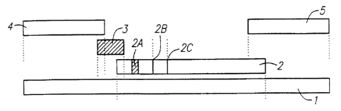
Figure 1 depicts an exemplary embodiment of the
invention. A series of porous material pieces (2), (3),
(4), and (5) are laminated to an elongated strip of a
semi-rigid material (1), such as vinyl and the like.
The separate sample receiving region (4) is a porous
material, preferably paper or a mixture of cellulose and
polyester. In the preferred embodiment shown in Fig.l,
the separate sample receiving region is in direct liquid
flow contact with the separate labeling reagent region
(3). This contact may be lateral flow contact, as shown
in Fig.l. Alternatively, this contact may be
perpendicular flow contact, with the separate sample
receiving region placed on top of the separate labeling
reagent region (not shown). The separate labeling reagent
region is in direct lateral flow contact with the analyte
detection region (2). The analyte detection region
contains a discrete zone containing the mobile labeling
CA 02272289 1999-05-18
WO 98/22800 PCT/US97/21245
27
reagent (2a). This labeling :reagent is the same reagent
found in the separate labeling reagent region (3), which
is capable of binding to the analyte.
In the embodiment shown in Fig. 9, the separate
labeling reagent region is in direct lateral flow contact
with the analyte detection reqion (2).
In this embodiment, the analyte detection region (2)
of the immunochromatographic assay device contains two
mobile labeling reagent in a discrete situs (2a), an
immobile indicator capture reagent in a discrete situs
(2b) and an immobile control capture reagent at a discrete
situs (2c). The mobile labeling reagent consists of a
first mobile labeling reagent which can bind the analyte
to be detected, i.e., an indicator labeling reagent.
Preferably the indicator labeling reagent is a monoclonal
or polyclonal antibody that specifically binds the analyte
to be detected. Attached to the antibody, either
covalently or noncovalently, is a substance or particle
capable of producing a signal detected visually. Such
particles used as labeling particles can be colloidal
gold, dye sols, colored latex and the like. Preferably,
the label is colored latex (blue) or gold sol. One
skilled in the art will recognize suitable labeling
particles. The second mobale labeling reagent is a
particle or molecule which does not recognize the analyte
and is conjugated to a substance or particle capable of
producing a signal, i.e., control labeling reagent.
Preferably, the control labeling reagent is BSA conjugated
to colored latex (Red) or gold sol.
The mobile indicator labeling reagent in the analyte
detection region may be the same indicator labeling
reagent found in the separate labeling reagent region (3),
which is capable of binding to the analyte. A strip of
plastic material (5), preferably clear mylar, is covered
on top of the device. Portion (5a) can be a window or
clear so as to permit viewing of the capture and control
discrete situses, i.e., to permit viewing of the results.
CA 02272289 1999-05-18
WO 98/22800 PCT/US97/21245
28
An end flow region (6) is in lateral flow contact with the
analyte detection region.
In the preferred embodiment shown in Fig. 2, the
separate sample receiving region (4) is in direct lateral
flow contact with the portion of the analyte detection
region (8) which contains the discrete zone or zones
containing the indicator labeling reagent and control
labeling reagent (8a). This portion of the analyte
detection region is in direct lateral flow contact with
the separate labeling reagent region (3). The separate
labeling reagent region is in direct lateral flow contact
with the portion of the analyte detection region (7)
containing the capture zones (7a and 7b).
The second portion of the analyte detection region (7)
is in direct lateral flow contact with the separate end
flow region (5). The assembly is such that there is end-
to-end contact of each region or overlaps sufficiently to
provide continuous wicking action (i.e., continuous
lateral flow). A strip of plastic material, preferably
clear mylar, may be covered on top of the device leaving
a portion of the front pad exposed for sample application
(not shown).
In an assay using the device shown in Figure 9, the
sample receiving region (4) of the assay device is
directly placed into a sample containing extracted
analytes, for example, a processed throat swab sample
which may contain extracted Streptococcus Group A
carbohydrate antigen, or a urine stream which may contain
hCG. The sample flows laterally along the porous material
region-by capillary action and migrates past the separate
labeling reagent region (3), and then past the labeling
reagents in the analyte detection region (2a). The
presence and/or the amount of analyte in the sample may
then be determined by the visibility of a signal line (2b)
formed by the specific binding of the immobilized
indicator capture reagent to the analyte-indicator
labeling reagent conjugate complex.
CA 02272289 1999-05-18
WO 98/22800 PCT/US97/21245
29
The appearance of a second signal (2c) may be utilized
as a built-in positive control signal. This positive
control signal results from binding of the immobilized
control capture reagent to the control labeling reagent,
e.g., BSA-Red latex. If the reagents and assay are
working properly, then a red signal line will appear at
(2c) the discrete control situ.s. The red control line is
an internal control. The test stick must absorb the
proper amount of the sample and the test stick must be
working properly for the red control line to appear. For
the test stick to be working properly, the capillary flow
must occur. Thus, the control line serves as an
indication that the proper amount of reagents have been
added to the assay chamber, and that sufficient lateral
flow has occurred for the control labeling reagent to
reach the control capture reagent zone.
The results of an assay can then be observed through
a viewing window (5a) covered by clear mylar.
In the embodiment shown in Figure 3, there is no
separate labeling reagent region. Mobile indicator
labeling reagent and control labeling reagent are placed
in the analyte detection recjion (2a). In addition,
labeled reagent (4a) can be impregnated near one end of
the sample receiving region (4).
In embodiments where the sample receiving region is in
direct contact with the analyte detection region,
illustrated in Figure 2, the analyte detection region may
be split into two portions (7) & (8). In this embodiment,
the first portion of the analyte detection region (8) is
in direct contact with the sample receiving region (4).
The first portion of the analyte detection region contains
a discrete zone containing the mobile indicator labeling
reagent and control labeling reagent (8a), and is also in
lateral flow contact with the separate labeling reagent
region (3). The separate labeling reagent region (3) is
in contact with the second portion of the analyte
detection region (7), which. contains the immobilized
CA 02272289 2007-07-31
72648-13
indicator capture reagent and control capture reagent (7a)
&(7b). The second portion of the analyte detection
region is in direct flow contact with the =ad flow region
(5) .
S Other layouts, for instance, of the upper covers or
the labeled particles are possible, as long as lateral
flow of the porous membranes is permitted. Overlap or
end-to-end connection can be used as long as lateral flow
occurs. Alternatively, the various regions of the test
10 strip may also be placed on a single porous member.
For example, the control labeling reagent and
indicator labeling reagent may be placed only in a region
of the analyte detection region, and the separate labeling
reagent region may be omitted. Alternatively, the control
15 labeling reagent and the indicator labeling reagent may be
placed only in a separate labeling reagent region, and
additional indicator labeling reagent or control labeling
reagent may be omitted from the analyte detection zone.
Thus, the present invention comprising an immuno-
20 chromatographic assay device increases the range of
sensitivity without increasing the clearance time or
increasing t~he incidence of false positives. Thus the
devices of this invention can be used to perform auick,
highly sensitive assays. In addition, the advantage of
25 using a same basic design with universal applicability for
different analytes also promotes the objective of
-jdnventory reduction.
One Exemplary Assay Device
Dimensions and construction of an immunoassay device
30 have been previously described in U.S. Patent
No. 5,712,172 invented by Ching Huang and Eugene Fan,
entitled One Step Immunochromatographic Device and Method
of Use. These procedures can be adapted in assembling
the devices of this invention using the following
dimensions. For instance, the sample application region
CA 02272289 2007-07-31
72648-13
31
can be shortened to accommodate the length of a separate
indicator reagent region.
Dimens.i.ons of the Exemplarv Assav Device
Upper Covering: 4 mm x 98 mm
Lower Back.ing: 4 mm x 98 mm
Separate Labeling
Reagent Region: 4 mm X 5 mm
Sample Receiving Region: 4 mm x 20 mm
End Flow Region: 4 mm x 56 mm
Analyte Detection Region:4 mm x 25 mm
Viewing Window: 4 mm x 9 mm
(Note: Product information may be printed on the
upper covering as shown i:n Figure 4.)
The device is required to have an adecquate total
mechanical strength (as defined above and discussed below)
in order for the device to function without diszupt=on of
lateral flow.
Selection of Materials for the Exetrcplary Device
1. AAalyte Detection Recriorn: Important features of the
material are its ability to wick fluids and to bind
proteins. Exemplary materials include nitrocellulose,
nylon or the like. In apreferred embodiment of this
invention, the material is nitrocellulose with or without
laminated solid support such as polyester. Nitroce:Llulose
is readily available from numerous suppliers.
2. Sample Receiving Reaion: Suitable materials include
cotton, cellulose, mixed fibers, glass fiber and the like.
For example, paper such as 470 and 740-E from Schleicher
and Schuell, Keen, NH, or D28 from Whatman, Fairfield, NJ,
can be selected for its high fluid absorption and wicking
speed. A more porous material such as glass fiber #66078
from Gelman Sciences, Ann Arbor, Mi, or "POREX*" from Porex
*Trade-mark
CA 02272289 1999-05-18
WO 98/22800 PCT/US97/21245
32
Technologies, Fairburn, GA, is suitable for impregnating
labeled particles.
3. Separate Labeling Reagent Region: A good candidate
would be a porous material which allows the ease of
releasing the impregnated labeling reagents from the
region. Such materials include glass fiber from Gelman
Sciences, Ann Arbor, MI, or Accuwik from Pall BioSupport,
Port Washington, NY.
4. Backinct Supports: For the present invention, the
preferred materials are clear mylar with thickness about
0.001 inches to 0.010 inches for the upper covering and
white vinyl with thickness about 0.001 inches to 0.030
inches for the lower backing. Both the mylar and the
vinyl sheets have adhesive on one side so as to attach the
porous material. Materials such as mylar, polyester, and
vinyl with adhesive are readily available.
5. Labeling Reagents: A chromogenic particulate such as
colored latex, colloidal gold, selenium or the like is
labeled with a suitable reagent specific for the targeted
analyte. For the present invention, the preferred
chromogenic particulate is colored latex or gold sol.
More preferably, blue or red colored latex or gold sol is
used. Latex and gold sol are commercially available from
a number of sources.
6. End Flow Recrion: Suitable materials include cotton,
cellulose, mixed fibers, glass fiber and other like
materials with high fluid absorption capacity. For
example, paper such as 470 and 740-E from Schleicher and
Schuell, Keen, NH, or D28 from Whatman, Fairfield, NJ, can
be selected for its high fluid absorption and wicking
speed.
7. Antibodies:
A. Strep A antibody: New Zealand white rabbits were
injected with partially purified Group A Streptococcus
antigen. The rabbits which produced a high titer of
antibody were identified by an enzyme immunoassay method.
CA 02272289 2007-07-31
72648-13
33
The sera from these rabbits were pooled and purif ied
through Strep A antigen affi.nity column.
$. Ant i-BS.A Ant ibodv : Affinity pur.i f ied sheep ant i-
B5A antibody was obtained from Bethyl Lab, Montgomery TX.
C. Monoclanal anti-8--hQ antibody: The monoclonal
anti-Q-hCG antibody can be obtained from Medix Si.otech
(San Carlos, CA), Medix Biochemica-(Kauniainen, Finland),
or other commercial sources. The affinity purified
polycl.onal anti-a--hCG antibody (rabbit) can be purchased
IO from Bioreclame.tion (East Meadow, NY), H.T.I. Bzo-
Products, Inc. (Ramona, CA) and other sources. As is
discussed below, the capture reagent recognizes the /3-
epitope of hCG while the control agent recognizes the a-
epxtope of hCG, or vice vezsa.
S. Preparation..of Latex Cou~u aq tes
The basic protocol for conjugation of protein to
latex, by simple adsorption or by covalent bindinq, is
well known in the art,.
For example, the indicator labeling reagent may be an
anti-Group A streptococcus antibody conjugated with blue
3.atex, while the indicator capture reagent may be an anti-
Group A streptococcus capture antibody_
Blue carboxylated latex particles (0.2 to 0.5 microns)
23 were activated with 0.2!k EDAC in the presence of 0.1$
sulfo-NHS in 20 mM MES buffer, pH 5.5, for 30 minutes at
=pm temperature. The excess' amount of reagents were
removed by washing in an Amicon Concentrator. The acti-
vated latex particles were resuspended in 2 mM MES buffer,
pH 6.5 to a concentration of 0.5;~, and a ratio of 0.05 mg
Strep A antibody were added to 1 mg of latex, The mixture
was incubated at room temperature for 2 hours. After
incubation, the conjugated latex was washed again to
remove free antibody. The antibody-latex conjugate was
then sonicated, filtered, and resuspended in buffer
containing 50 mM Tris, pH 8.5; 20% sucrose; 2.0k casein,
and 0.1% sodium azide.
CA 02272289 2007-07-31
72648-13
34
The conjugation of BSfi to re.d carboxylated latex (size
of 0.2 to 0.5 microns) was essentially-' the same as de-
scribed above exCept replaced the blue latex with red
latex and Strep A antibody with BSA.
9. PreAaration of Latex Coatincr Solution
The blue latex solution and the red latex solution
were mixed at a ratio from 5:1 to 1:1 depends upon the
sensitivity of the conjugate and intensity of red control
line desired. The preferable ratio is approximate l:z.
These solutions are then impregnated into the porous
mate.x'ial using methods well known in the art,
10. Coatincof_Capture Reagents on t.he Discrete Situses of
the Analyte Detection Reaion
Thin lines of the indicator capture reagent or control
capture reagent were applied on the material using
airbrush techniques (Iwata, model HP-13C2 ), The width, of
the lines can be 0.2 mm to 2 mm, a width of 1 mm is
preferred. Such material is immobilized by techniques
well known in the art,
11. Coatinq of Latex Coniugate (Labeling Reaaents) on the
Analyte Detectiorx Region
immediately after the capture reagents were applied on
the material. The latex solution can be applied on the
material by using airjet techniques such as BioDot
niodoser machine from Bio-DQt, Inc., Irvine, CA. The
#telrtbraxte strip is then dried in a force air oven at 700C
for 45 minutes. Such application allows the labeling
reagents to be taobile.
12. Preparation of Separate Labe].ing Reacrent Region
The separate labeling reagents region is prepared by
-saturating a piece of porous material such as Accuwik with
the prepared latex coating solution. The latex solution
containing the indicator labeling reagent for the analyte
was applied to ACCUWZK'* AW14-2084 (Pall BioSupport, Part
Washington, NY) at saturation volume and then dried in a
CA 02272289 1999-05-18
WO 98/2280() PCT/US97/21245
forced air oven at 700 C for 30 minutes. Labeling reagent
applied by this method will remain mobile.
13. Preparation of Sample Receiving Region
In this invention, the sarnple receiving region may not
5 only absorb and transport liquid sample, it may also func-
tions as a specimen collection apparatus and as a
buffering agent or a neutralizing agent for an acidic
extraction solution. The sample receiving region may
comprise a paper treated with buffer, detergents, blocking
10 proteins and the like to facilitate movement of dried
latex particles or to reduce nonspecific binding of the
assay. In the case of the Strep A assay, 740E paper was
soaked in a buffer solution, dried, and then assembled
into the assay device. Specifically, buffer solution
15 containing 1.5% zwittergent 3-12, 0.1% sodium azide, 0.1%
rabbit gamma globulin, 0.1 M NaCl and 0.2 M Tris, pH 9.0
was used.
In the case of the hCG assay, an appropriate amount of
buffer solution was dispensed to the separate labeling
20 reagent region (labeling pad), dried, and then assembled
into the assay device. Specifically, 0.4 mL of buffer
solution containing 4% zwitte:rgent 3-12, 1% rabbit gamma
globulin, 1% casein and 200 mM Tris, pH 8.5 were applied
on 254 mm long strip of front pad at it's edge. The
25 sample receiving region is then dried in a forced air oven
at 70 C for 15 minutes.
14. Assembly of the Assay Device
A sheet of white vinyl (98 mm x 254 mm) is placed on
a flat surface. The cover paper on the white vinyl sheet
30 is removed to expose the adhesive. A strip of the analyte
detection region (25 mm x 254 mm) containing latex and
antibody lines is attached to the white vinyl sheet. A
strip of the sample receivinq region (20 mm x 254 mm) is
attached to the left edge of the white vinyl sheet. A
35 separate labeling reagent region (5 mm X 254 mm) is
layered between the sample receiving region and the white
CA 02272289 1999-05-18
WO 98/22800 PCT/US97/21245
36
vinyl sheet. The internal ends of the separate labeling
reagent region and the sample receiving region are lying
flush, and overlapping the analyte detection region by 1.5
mm. The end flow region (56 mm x 254 mm) is attached to
the right edge of the white vinyl sheet while overlapping
about 1.5 mm on top of the analyte detection region. The
cover paper from the clear mylar sheet is removed (98 mm
x 254 mm) to expose the adhesive. Centering the window
region of the clear mylar sheet over the capture reagent
lines in the analyte detection region, the clear mylar
sheet is attached with the adhesive side down on top of
the end flow region, analyte detection region and sample
receiving region. The whole sheet is pressed with a
roller to ensure the lamination is secure. The laminated
sheet is then cut to 4 mm wide sticks.
In yet another aspect, the present invention compris-
ing an immunochromatographic assay device without molded
plastic casings greatly reduces the cost for manufactur-
ing. In addition, the advantage of using a same basic
design with universal applicability for different analytes
also promotes the objective of inventory reduction.
EXAMPLE 1--One-Step Immunoassay for Strep A Which Does Not
Require Sample Manipulation
Most preferably the one-step assay device will contain
an OSOM'm Strep A Test . The OSOMTM Strep A Test detects
either viable or nonviable Group A Streptococcus organisms
directly from a throat swab, providing results within 5
minutes.
Specimens may be collected with a sterile swab from
the tonsils and/or the back of the throat, taking care to
avoid the teeth, gums, tongue or cheek surfaces. Sterile
swabs may be used to collect the specimens. Preferably
sterile rayon or dacron swab are used to collect
specimens. Alternately, swabs with transport tubes
containing liquid media can also be used. Preferably the
liquid media used in transport tubes will be Modified
CA 02272289 1999-05-18
WO 98/22800 PGT/US97/21245
37
Stuart's Transport Media ("C'ULTURETTE" available from
Becton Dickinson).
The OSOMTM Strep A Test can be used for the qualitative
detection of Group A Streptococcal antigen from throat
swabs or confirmation of presuniptive Group A Streptococcal
colonies recovered from culture.
The assays as described provide a method for antigen
extraction from the sample and introduction of the device
into the sample containing extracted analytes without the
need for specimen manipulation following the extraction.
This provides an advantage of a more rapid and convenient
test procedure to the user.
Test Procedure for running the OSOM Strep A Test:
Just before testing, 3 drops Reagent 1 (2M sodium
nitrite) (pink) and 3 drops Reagent 2 (0.3 M acetic acid)
were added to the Test Tube (the solution should turn
light yellow). The swab (Purl?ybr Inc., Munster, IN) was
immediately inserted into the tube. Vigorously mixing of
the solution by rotating the swab forcefully against the
side of the Tube at least ten times. (Best results were
obtained when the specimen was vigorously extracted in the
solution.) The samples were left standing for one minute.
As much liquid as possible was expressed from the swab by
pressing the swab firmly against the side of the Tube.
The swab was discarded. An OSOM'm Strep A Test Stick was
then placed into the extracteci sample. The results were
read at 5 minutes.
Comparison of the Sensitivity of Results of the OSOMT"
Assay for Streptococcus Group A and Other One-Step Assays
Procedure:
Strep A cells were picked up from a pure culture plate and
suspended in saline solution. Subsequent serial dilutions
were made with saline to yield different concentrations of
cell suspension. The cell concentration was determined by
the optical density method. OD650 of 1 is equivalent to
CA 02272289 1999-05-18
WO 98/22800 PCT/US97/21245
38
approximately 2x10⁹ cells/mL in suspension. 25 L of the
suspension was pipetted onto the tip of each of the swabs
supplied by the manufacturers. Tests were performed
within 5 minutes after the swabs were spiked with cell
suspension. Tests were performed by following procedure
described in each prospective manufacturer's directional
insert.
Results:
Cell Qty/Swab 4x10 4x10 8x10 4x10
Wyntek OSOM Positive Positl.ve Weak Weak
Positive Positive
Quidel Positive Positive Weak Negative
Positive
Binax Positive Positive Negative Negative
These results indicate Wyntek OSOMTM Strep A Test can
detect Group A Streptococcus cells when present at a
concentration as low as 4x10⁵ cells per swab, while
Quidel's and Binax's tests can only detect Strep A cells
when present at a concentration of 8x10⁵ cells per swab or
4 X 10⁶ cells per swab, respectively.
Performance of OSOMTM Strep A Test in Clinical Trials
In a multi-center evaluation, a total of 639 throat
swabs were collected from patients presenting with
pharyngitis. Each swab was inoculated to a sheep blood
agar plate, then tested by the OSOM Strep A Test. Plates
were incubated for 18-24 hours at 35 -37 C at 5-10% CO2
with a Bacitracin disk. Presumptive GAS colonies were
confirmed with commercially available Strep A testing
kits.
Of the 639 total specimens, 464 were found to be
negative by culture and 454 were also negative by the OSOM
Strep A Test, for a specificity of 97.8%. Of the 175
specimens found to be positive by culture, 168 were also
positive by the OSOM Strep A Test, for a sensitivity of
96.0%. The 95t confidence intervals were calculated to be
CA 02272289 1999-05-18
WO 98/22800 PCT/US97/21245
39
96.6-99.0% for specificity and 94.4-97.6% for sensitivity.
Overall agreement between culture and the OSOM Strep A
Test was 97.3% (622/639).
The results are summarized below:
Culture OSOM Cu ture % Correct
Classification
Negative 454/464 97.8%
(Specificity)
1+ s10 co onies 3i76 50. 0%
2+(11-50 co onies 9 13 69.2%
3+(>50 co onies 44/44 100%
4+ pre ominant 112i112 100%
growth)
Tota Positive 168i175 96.0%
(Sensitivity)
Total 622i 639 97.3%
(Overall Agreement)
In addition, the OSOM Strep A Test was used to confirm
the identification of Group A Streptococcus on blood agar
plates. As a culture confirmation test, the OSOM Strep A
Test was 100% sensitive (62/62) and 100% specific (39/39) .
The following organisms tested at levels of
approximately 1 x 10⁸ organism.s/test were all found to be
negative when tested with the OSOM Strep A Test:
CA 02272289 1999-05-18
WO 98/22800 PCT/US97/21245
Streptococcus Group B
Streptococcus Group C
Streptococcus Group F
Streptococcus Group G
5 Streptococcus pneumoniae
Streptococcus sanguis
Streptococcus mutans Enterococcus faecalis
Staphylococcus aureus
Staphylococcus epidermidis
10 Corynebacterium diptheria
Serratia marcescens
Candida albicans
Klebsiella pneumoniae Pseudomonas aeruginosa
Bordetella pertussis
15 Neisseria meningitides
Neisseria gonorrhoeae
Neisseria sicca
Neisseria subfiava
Branhamella catarrhalis
20 Hemophilus influenza
Example 2: Procedure for Testing the Presence or Absence
of Human Chorionic Gonadotropin (hCG) in Lictuid Samples
Samples containing hCG were applied to the sample
receiving region of the assay device. The device is then
25 placed on a paper towel. Within one minute, the test
result, if positive for hCG, will appear as one blue line
together with one red line. If only a red line appears
then the results are negative. The red latex is used as a
control to ensure the assay reagents are working and that
30 lateral flow is occurring.
Determination of Clearance Times and Relative
Sensitivities
Three types of devices were assembled: (1) devices
with labeling reagent (referred to in this example as a
35 label) placed only in a separate labeling reagent region
CA 02272289 1999-05-18
WO 98/22890 PCT/US97/21245
41
(referred to in this example as a label pad); (2) devices
with label reagent placed only in a discrete labeling zone
of the analyte detection reqion (referred to in these
examples as the label zone); and (3) a hybrid device with
labeling reagent placed in both the label zone and the
label pad (referred to in these examples as "the hybrid").
The triplicate strips were run by application of a
negative control sample solution to the sample pad. The
color development at the capture zone was measured with
the CR-241 at 30 second intervals for approximately 10
minutes.
At various time points, the reflectiveness (E values)
intensity at the capture zone was recorded using a Minolta
Chroma Meter CR-241.
Table 1 shows the intensities (E) at the capture zone
at various time points for the three types of devices.
The hybrid device contains the same amount of dye in the
label pad as the device containing dye only in the label
pad; the hybrid device also contains the same amount of
dye in the label zone as the device containing dye only in
the label zone.
CA 02272289 1999-05-18
WO 98/22800 PCT/US97/21245
42
Table 1
E Values
Time Label Pad Label Zone Hybrid
(min) Only Only
0.50 1.64 1.55 1.56
1.00 1.63 1.49 1.48
1.50 6.36 15.01 14.75
2.00 9.75 9.65 15.02
2.50 10.2 8.45 15.19
3.00 10.3 7.97 13.88
3.50 9.82 7.25 12.97
4.00 9.66 7.09 12.1
4.50 9.42 6.87 11.58
5.00 9.49 6.67 10.91
5.50 9.81 6.48 10.12
6.00 8.27 5.72 9.16
6.50 7.31 5.98 8.7
7.00 7.26 6.02 8.33
7.50 7.2 6.06 8.14
8.00 7.05 6 7.95
8.50 6.1 6.02 7.84
9.00 6.1 6.02 7.75
9.50 6.06 7.74
10.00 5.96 7.73
10.50 7.74
11.00
11.50
12.00
When the sample is applied, lateral flow mobilizes the
labeling reagent. As the reagent begins to pass the
capture zone, the measured intensity increases. As some
of the labeling reagent is mobilized, the amount of
labeling reagent remaining in the separate labeling
reagent region and/or in the discrete zone begins to
decrease. Gradually the amount of labeling reagent
passing the capture zone begins to decrease until it falls
sufficiently to permit accurate reading of the positive
and negative results. The clearance time is an important
factor in determining the time necessary to complete the
assay.
Figure 4 shows a graph of the intensity at the capture
zone vs. the time in minutes. As can be seen from the
graph (^-^), placement of the labeling reagent in the
discrete zone only results in a quick increase in the
concentration of labeling reagent passing the capture
CA 02272289 1999-05-18
WO 98/22800 PCTIUS97/21245
43
zone, followed by a quick decrease. This type of device
has a quick clearance time but lower sensitivity--the time
for the analyte to bind to the indicator labeling reagent,
and the time for the analyte-indicator reagent complex to
bind to the capture reagent. are shorter--as shown in
Figure 5(o-0). While the detection of low concentrations
of analyte can be improved by increasing the amount of
labeling reagent in the discrete zone, this increase also
increases the maximum concen1tration of labeling reagent
passing through the capture zone (See Figure 6), which may
increase the occurrence of false positive results (data
not shown).
Alternatively, placement of the labeling reagent in
the separate labeling reagent region only (in this example
a "label pad"), results in a slow increase in the
concentration of labeling reagent passing through the
capture zone, followed by a slower trailing decrease in
the amount of labeling reagent passing through the capture
zone (Figure 4,+ -*). Increasing the amount of labeling
reagent in the separate labeling reagent region to
increase the amount of labeling reagent which passes the
capture zone results in greater clearance times, greater
time for the analyte to bind to the indicator labeling
reagent, and greater time for the analyte-indicator
reagent complex to bind to the capture reagent, which
results in sustained release and greater sensitivity
(Figure 7).
Placement of the label in both the label zone and a
separate labeling reagent region in the "hybrid" device
gives rise to a quick increase in the concentration of the
label moving past the capture zone (Figure 4,=-A) .
Because the labeling reagent is also placed in a separate
labeling reagent region, this high concentration of
labeling reagent persists for a longer period than when
the labeling reagent is placed in the label zone alone,
permitting a longer incubation of the indicator labeling
reagent with the analyte and a longer incubation of the
CA 02272289 1999-05-18
WO 98/22800 PCT/US97/21245
44
analyte-indicator labeling reagent complex with the
indicator capture reagent. The total amount of analyte-
indicator labeling reagent complex passing through the
capture zone is thereby increased, permitting a higher
range of sensitivity of the assay device. However,
although the range of sensitivity is increased, the
maximum level of label passing through the capture zone at
any given time point does not exceed the maximum level
obtained from placement of the label in the discrete zone
only. Therefore, placement of the labeling reagent in
both positions increases sensitivity with respect to
placing the labeling reagent in a discrete zone without
increasing the occurrence of false positive readings.
Moreover, the time needed for the concentration of the
label to fall to background levels is not significantly
increased compared to the device containing the label in
the separate labeling reagent region alone. Therefore,
clearance time is not adversely affected.
Sensitivity Curve
Samples containing various amounts of target analyte
(hCG) were applied to the same three types of assay
devices described above, and carried out as described.
The intensity of the band formed in the capture zone
through binding of the (hCG)-anti-P-hCG antibody-blue
latex complex to anti-aa-hCG antibody capture reagent was
measured at each hCG concentration. The data is shown in
Table 2.
CA 02272289 1999-05-18
WO 98/22800 PCT/US97/21245
TABLE 2
hCG Concentration La e Pad La e Zone Hy ri
(mIU/ml ) Only Only
15 1.54 0.51 2.36
5 30 3.98 1.23 5.2
62.5 7.87 1.62 6.84
125 10.15 2.52 8.82
250 10.57 4.92 14.63
500 12.11 7.68 23.49
10 2000 13.81 10.2 26.51
20000 15.96 14.81 22.99
200000 8.1 11.51 19.28
2000000 1.86 4.77 8.2
Figure 5 shows a graph of the intensity vs. the hCG
15 concentration in mI-J/ml.
At low concentrations, the device containing the
labeling reagent in a discrete label zone has the lowest
sensitivity (Figure 5, ^-^). The "hybrid" device has
sensitivity comparable to p:lacement of the indicator
20 reagent in the separate labeling reagent region alone (*-
=) at concentrations of hCG less than 100 mIU/ml hCG,
while the hybrid has the highest sensitivity at
concentrations above 100 mIU/nil hCG (A-A).
Comgarison of Hiah vs. Low % Solids (Labeling Reagent
25 Concentration) in a Separate Labeling Reactent Region
(Label Pad) And Comparison of Hicth vs. Low % Solids
(Labeling Reagent Concentration) in a Discrete
Labeling Zone of the Analyte Detection Reaion (Label
Zone)
30 Assay strips were assembled as described above with
two different concentrations of label in the label pad and
two different concentrations of label placed in the
discrete zone of the analyte detection region. The low
concentrations of label in the label pad and in the label
35 zone are equivalent in total % solids. The high
concentrations of the label in the label pad and in the
label zone are also equivalent in total solids. The total
solids in the high concentration is approximately twice
the total solids in the low concentrations. As in the
40 experiments above, assay strips were assembled with label
CA 02272289 1999-05-18
WO 98/22800 PCT/US97/21245
46
pad only, label zone only, and hybrid (both label pad and
label zone). The triplicate strips were run by
application of a negative control sample solution to the
sample pad. The color development at the capture zone was
measured with the CR-241 at 30 second intervals for
approximately 10 minutes. E values were recorded for each
time interval and are set forth in Table 3.
TABLE 3
E Values
Label Zone Label Pad
Time Hybrid
Low ~ High $ Low High ~
(min)
0.50 2 2 2 2 2
1.00 12.96 35.63 3.48 8.5 14.55
1.50 3.99 6.11 5.42 12.63 16.92
2.00 3.18 4.29 5.31 14.52 15.89
2.50 2.92 3.48 5 14.81 13.78
3.00 2.75 3.05 4.79 14.26 12.57
3.50 2.54 2.78 4.72 13.91 11.58
4.00 2.3 2.61 5.03 12.66 10.21
4.50 2.15 2.53 5.18 12.02 9.06
5.00 2.09 2.47 4.29 11.68 8.57
5.50 2.04 2.42 3.54 11.33 8.04
6.00 1.99 2.38 3.16 10.95 7.85
6.50 1.97 2.32 2.93 10.42 7.71
7.00 1.94 2.18 2.79 9.73 7.5
7.50 1.93 2.09 2.68 9.12 7.43
8.00 1.93 2.01 2.62 8.68
8.50 1.91 1.98 2.45 8.36
9.00 1.9 1.92 2.32 8.11
9.50 1.91 1.8 2.05 7.92
10.00 1.9 1.9 1.98 7.88
10.50 1.89 1.75 1.97 7.79
11.00 1.88 1.77 1.88 7.68
11.50 1.88 1.75
12.00
Figure 6 shows that the maximum concentration of label
passing through the capture zone increases if the amount
of the label in the label zone is increased. This may
lead to an increase in the number of false positive
results. In addition, the time that the analyte-label
reagent complex has to react with the capture reagent is
not increased.
CA 02272289 2007-07-31
72648-13
47
Figure 7 shows that both the maximum concentration of
iabel passing through the capture zone and the time that
it takes for the label to clear the capture zone is
increased if the amount of label in the label is
s increased. This would give rise to longer assay times and
would increase the possibility of false positive results.
Figure 8 shows the intensity curve where the total
label in the hybrid device is approximately the same
amount of label coritained in the label pad of the device
zo containing high o label in the label pad only, and is also
approximately the same amount of label contained in the
label pad of the device containing high o in the label
zone ornly.
One skilled in the art will readily appreciate that
j.5 the present invention is well adapted to carry out the
objects and obtain the ends and advantages mentioned as
well as those inherent therein. The immunologicai methods
and devices for detecting analytes in biological samples
as described herein are presently representative of
20 preferred embodiments, are exemplary and not intended as
limitations on the scope of the invention_ Changes
therein and other uses will occur to those skilled in the
art which are defined by the scope of the claims.
25 it wi].1 be readily apparent to one skilled in the art
that varying substitutions and modifications may be made
to the invention disclosed herein without departing from
the scope of the claimed invention.
All patenta and publications mentioned in the specifi-
30 cation are indicative of the levels of those skilled in
the art to which the invention pertains.