Language selection

Search

Patent 2272391 Summary

Third-party information liability

Some of the information on this Web page has been provided by external sources. The Government of Canada is not responsible for the accuracy, reliability or currency of the information supplied by external sources. Users wishing to rely upon this information should consult directly with the source of the information. Content provided by external sources is not subject to official languages, privacy and accessibility requirements.

Claims and Abstract availability

Any discrepancies in the text and image of the Claims and Abstract are due to differing posting times. Text of the Claims and Abstract are posted:

  • At the time the application is open to public inspection;
  • At the time of issue of the patent (grant).
(12) Patent Application: (11) CA 2272391
(54) English Title: BENCH FOR MACHINING ELONGATE OBJECTS SUCH AS STRIPS OF MARBLE AND THE LIKE
(54) French Title: BANC D'USINAGE D'OBJETS DE FORME ALLONGEE TELS QUE DES BANDEAUX DE MARBRE ET SIMILAIRE
Status: Dead
Bibliographic Data
(51) International Patent Classification (IPC):
  • B24B 41/06 (2012.01)
  • B24B 9/06 (2006.01)
  • B24B 23/02 (2006.01)
  • B28D 7/04 (2006.01)
(72) Inventors :
  • LUPI, QUINTILIO (United Kingdom)
(73) Owners :
  • LUPI, QUINTILIO (United Kingdom)
(71) Applicants :
  • LUPI, QUINTILIO (United Kingdom)
(74) Agent: FETHERSTONHAUGH & CO.
(74) Associate agent:
(45) Issued:
(86) PCT Filing Date: 1997-11-18
(87) Open to Public Inspection: 1998-05-28
Availability of licence: N/A
(25) Language of filing: English

Patent Cooperation Treaty (PCT): Yes
(86) PCT Filing Number: PCT/IT1997/000284
(87) International Publication Number: WO1998/022258
(85) National Entry: 1999-05-17

(30) Application Priority Data:
Application No. Country/Territory Date
RM96A000798 Italy 1996-11-22

Abstracts

English Abstract


The bench for machining elongate objects such as strips of marble and the like
comprises a generally boxlike body having a surface over which a portable
profiling machine can be moved and a side comprising means for holding
elongate objects or strips or the like in position by means of a plurality of
pneumatic suction inlets which, by the action of low pressure, hold the
elongate object stably during its machining.


French Abstract

La présente invention concerne un banc d'usinage d'objets de forme allongée tels que des bandeaux de marbre et similaire. Le corps de ce banc présente la forme générale d'un coffre. Sur une face de ce coffre, on peut faire circuler une machine à profiler portable. Un côté du coffre est équipé d'organes destinés à maintenir en position des objets de forme allongée. Ce maintien en position est assuré par une pluralité de ventouses pneumatiques qui, sous l'effet de la dépression, maintiennent stable l'objet de forme allongée pendant son usinage.

Claims

Note: Claims are shown in the official language in which they were submitted.


6
Claims
1. Bench for machining elongate objects such as strips of marble and
the like, characterized in that it comprises a generally boxlike body
having a surface over which a portable profiling machine can be moved
and a side comprising means for holding elongate objects or strips or the
like in position by means of a plurality of pneumatic suction inlets which,
by the action of low pressure, hold the elongate object stably during its
machining.
2. Machining bench according to Claim 1, characterized in that the
pneumatic suction inlets are elongate in the direction of the length of the
marble strip or strips to be machined.
3. Machining bench according to Claim 2, characterized in that the
pneumatic suction inlets are connected to a vacuum reservoir via tubes.
4. Machining bench according to Claim 3, characterized in that said
tubes are fitted in an intermediate position with valve means for the
selective activation or deactivation of one or more of the pneumatic
suction inlets.
5. Machining bench according to one or more of the preceding claims,
characterized in that the vacuum reservoir is connected to a vacuum
source consisting of a Venturi-effect ejector activated by compressed air.
6. Machining bench according to one or more of the preceding claims,
characterized in that the vacuum reservoir is fitted on its underside with
a valve for discharging liquids that may collect inside the vacuum
reservoir.


7
7. Machining bench according to one or more of the preceding claims,
characterized in that the vacuum reservoir is connected via a valve to a
connector for pressurization.
8. Machining bench according to one or more of the preceding claims,
characterized in that it is arranged to operate in combination with a
portable profiling machine equipped with a lubricated and cooled grinding
wheel.
9. Bench for machining elongate objects such as strips of marble or
the like according to one or more of the preceding claims and essentially
as described and illustrated with reference to the figures of the
accompanying drawings.

Description

Note: Descriptions are shown in the official language in which they were submitted.


CA 02272391 1999-OS-17
WO 98/22258 PCT/iT97/00284
1
Bench for machining eloneate ob ects such as strius of marble and the like
The present invention relates to a bench for machining elongate objects of
marble and the like.
Decorative strips of marble or the like requiring special machining for
their shaping and polishing and other operations are in current use.
One difficulty encountered in the machining of objects of this kind on a
craft or semi-craft basis, without resorting to large machines for
industrial machining whose use for small work would be uneconomical, is
that of how to fix a workpiece securely so that a portable-type moulding
machine can work on it.
Clearly, this temporary fixing of objects of elongate shape or strips of this
kind for the purpose of machining them must be stable and secure, and
yet must not use clamps or equivalent means which would interfere with
the machining processes, especially when portable profilers of known type
are used.
It is therefore an object of the present invention to provide a machining
bench for machining elongate objects or strips of marble or the like that
have to be machined in the direction of their length without requiring the
use of clamp-type fixing means or equivalents thereof.
The present invention provides a bench for machining elongate objects
that comprises a generally boxlike body having a surface over which a
portable profiling machine can be moved, and a side comprising means for
holding strips or the like in position by means of a plurality of pneumatic
suction inlets which, by the action of low pressure, hold the elongate
object stably during its machining.


CA 02272391 1999-OS-17
WO 98/ZZ258
PCT/lT97/00284
2
The present invention also provides an element for supporting the
workpiece and positioning it correctly, with the aid of a pair of graduated
elements arranged for the repeatable adjustment of the position of the
workpiece and for ensuring it is parallel with the upper surface of the
machining bench.
The present inventio will now be described with reference to a currently
preferred embodiment of the same, supported by the figures of the
appended drawings, in which:
Figure 1 is a perspective view of the machining bench according to the
present invention;
Figure 2 is a perspective view of the machining bench shown in Figure 1
on which an elongate object or strip extending roughly the full length of
the machining stroke is fixed for machining;
Figures 3 and 4 are views similar to Figure 1 of the machining bench, on
each of which are fixed workpieces with different proportions to those of
the strip object shown in Figure 2;
Figure 5 shows the same view of the machining bench of Figure 1, on
which different types of strip object are fixed;
Figure 6 is a side view of the machining bench according to the invention
with parts removed to show the internal components; and
Figure 7 is a side view of the machining bench according to the invention
in conjunction with a typical profiling machine.
Referring to the abovementioned figures, the machining bench comprises
a boxlike body 1 standing on feet 2, 3 and having an upper surface 4 over


CA 02272391 1999-OS-17
WO 98/22258 PCT/1T97/00284
3
which a profiling machine can be moved, and a surface 5 against which
the elongate objects or strips to be machined are leaned and on which
they are retained.
As can be observed in Figure 1, the surface 5 has a plurality of low-
pressure pneumatic suction inlets 6, 7, 8, 9 running along the top close to
the edge formed by surfaces 4 and 5. At the ends of the surface 5 are two
grooved elements 10, 11 having slots 12 in which clamping pins 13, visible
in Figure 6, can slide. These pins 13 are connected to levers 14, 15 for
clamping in position a supporting bar 16 comprising a right-angled
stiffening part 17.
Parts 10, 11 are conveniently provided with a millimetric or other similar
scale 18, 19 to provide a positioning reference with respect to the upper
surface 4 of the supporting bar 16 on which the workpieces are rested.
As can be seen, Figures 2 to 5 show the same view of the machining bench
as in Figure 1, on which various types of elongate objects or strips are
positioned and fixed for machining.
More particularly, Figure 2 shows the machining bench of the invention
on which is positioned a strip object 20 of considerable longitudinal
length; Figure 3 shows the machining bench on which an elongate object
or strip 21 of considerable extent both longitudinally and transversely is
positioned.
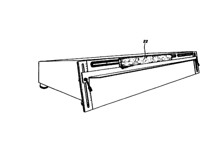
In Figure 4 the workpiece 22 occupies only part of the maximum
acceptable length of the elongate objects or strips for machining, and
Figure 5 shows a number of different elongate strip objects 23, 24, 25 for
machining, varying in type and longitudinal length, secured
simultaneously to the same machining bench.


CA 02272391 1999-OS-17
WO 98/22258
4
PCT/11'97/00284
Figure 6 shows the low-pressure pneumatic suction inlets 6, 7, 8, 9
connected by tubes 26, 27, 28, 29. Each of these tubes has its own on-off
valve 30, 31, 32, 33 which come together at 34 in a vacuum reservoir 35
well known in the art.
The reservoir 35 is connected by a tube 36 to a pneumatic vacuum
generator employing a compressed-air ejector operating by the Venturi
effect, marked 37 and well known per se, so it will not be described in
further detail.
The vacuum generator 37 is connected via a valve 38 to a compressed air
admission connector 39.
The reservoir 35 can, when necessary, be pressurized with compressed air
through a connector 40. The reservoir 35 is also connected to a valve 41
for discharging water or other liquids, which may perhaps collect in it as a
consequence of the grinding wheel operations, which are usually carried
out with the aid of lubricating coolants, preferably water-based, which
can be sucked in by the suction elements 6, 7, 8, 9.
Clearly, valves 30, 31, 32, 33 can be operated selectively to suit the
dimensions of the work material in the longitudinal direction.
It should be noted, in addition, that the vacuum reservoir 35 helps in
equalizing the suction action of the suction elements 6, 7, 8, 9.
With reference to Figure 7, the machining bench according to the
invention is shown in combination with a profiling machine 42 which uses
a grinding wheel 43 to machine a generic strip 44 while the latter is held
in position.


CA 02272391 1999-OS-17
WO 98/Z2258 PCT/IT97100284
The present invention has been described with reference to one currently
preferred embodiment thereof, but it will be understood that alterations
. and modifications can be made in practice by those skilled in the art
without departing from the scope of protection of the present industrial
. property document.

Representative Drawing
A single figure which represents the drawing illustrating the invention.
Administrative Status

For a clearer understanding of the status of the application/patent presented on this page, the site Disclaimer , as well as the definitions for Patent , Administrative Status , Maintenance Fee  and Payment History  should be consulted.

Administrative Status

Title Date
Forecasted Issue Date Unavailable
(86) PCT Filing Date 1997-11-18
(87) PCT Publication Date 1998-05-28
(85) National Entry 1999-05-17
Dead Application 2002-11-18

Abandonment History

Abandonment Date Reason Reinstatement Date
2001-11-19 FAILURE TO PAY APPLICATION MAINTENANCE FEE

Payment History

Fee Type Anniversary Year Due Date Amount Paid Paid Date
Application Fee $150.00 1999-05-17
Maintenance Fee - Application - New Act 2 1999-11-18 $50.00 1999-11-03
Maintenance Fee - Application - New Act 3 2000-11-20 $50.00 2000-10-04
Owners on Record

Note: Records showing the ownership history in alphabetical order.

Current Owners on Record
LUPI, QUINTILIO
Past Owners on Record
None
Past Owners that do not appear in the "Owners on Record" listing will appear in other documentation within the application.
Documents

To view selected files, please enter reCAPTCHA code :


To view images, click a link in the Document Description column. To download the documents, select one or more checkboxes in the first column and then click the "Download Selected in PDF format (Zip Archive)" or the "Download Selected as Single PDF" button.

List of published and non-published patent-specific documents on the CPD .

If you have any difficulty accessing content, you can call the Client Service Centre at 1-866-997-1936 or send them an e-mail at CIPO Client Service Centre.


Document
Description 
Date
(yyyy-mm-dd) 
Number of pages   Size of Image (KB) 
Representative Drawing 1999-08-12 1 6
Cover Page 1999-08-12 1 40
Abstract 1999-05-17 1 50
Description 1999-05-17 5 181
Claims 1999-05-17 2 60
Drawings 1999-05-17 7 109
Assignment 1999-05-17 2 84
PCT 1999-05-17 8 401
PCT 1999-06-30 1 31