Note: Descriptions are shown in the official language in which they were submitted.
CA 02272526 1999-OS-21
TANK VENTING ARRANGEMENT FOR MOTOR VEHICLES
Field of the Invention
The invention relates to tank venting arrangements for motor vehicles and
especially
to tank venting arrangements with controllable throughput.
Background of the Invention
For environmental reasons, continuous efforts are being made to reduce
emissions
from combustion engines. However, exhaust treatment alone does no longer
satisfy
today's requirements. The release of low-boiling fuel components from the fuel
tank
should also be avoided. For this reason, closed fuel tank venting arrangements
were
introduced wherein fuel vapours exiting from the fuel tank are fed through a
vent
conduit to an adsorption filter. However, since the activated charcoal of the
filter has
only a limited storage capacity, the filter must be flushed with ambient air
and the
fuel vapours fed to the engine for combustion. The fuel vapours must be fed in
controlled amounts to ensure a clean combustion.
In vehicles with carburated engines, or four-stroke engines with fuel
injection, the
fuel vapours are transported by the vacuum present in the intake pipe of the
carburator. However, this process is not applicable satisfactory with direct
injected
engines which provide large fuel savings. Difficulties also are encountered
with
charged four-stroke engines, since over significant operating ranges the
pressure in
the intake manifold is higher than the atmospheric pressure. Solutions are
therefore
desired for better controlling the flow of the flushing fluid.
German Published Application DE-OS 196 39 116 discloses a tank venting
arrangement for motor vehicles wherein an air pump is used for control of the
regeneration amount which is the amount of fluid used to flush the adsorption
filter.
Such an arrangement is independent of the vacuum in the intake pipe of the
engine.
The air pump is operated as a dosing pump with variable rotation speed. It can
also
CA 02272526 1999-OS-21
__ ... _2_
be used as a diagnosis pump for the detection of leakage in the venting
arrangement. Such an arrangement, however, has a relatively high inertia,
since the
pump reacts to changes in the engine output with too much of a delay.
Summary of the Invention
It is an object of the invention to provide a tank venting arrangement wherein
the
regeneration flow to the filter is independent of the pressure conditions at
the engine
to ensure a preselected regeneration flow in the range from maximum output to
idling of the engine, and wherein the arrangement reacts without delay to
changes in
the engine output. The regeneration flow is preferably proportional to the
engine
throughput.
This object is achieved in a tank venting arrangement in accordance with the
invention for motor vehicles with a fuel tank, which arrangement includes an
adsorption filter connected by a vent conduit to the fuel tank for the storage
of fuel
vapours and having a closeable air intake, and a regeneration conduit to the
engine
in which an air pump is positioned, and a regeneration valve for control of a
flow of
regeneration fluid in the regeneration conduit before the air pump, which
regeneration valve is controlled by the engine management system. Tests have
shown that this arrangement of regeneration valve and air pump provides
surprisingly good results. It is an advantage that the arrangement is closed
by way
of the regeneration valve when the engine is shut off. At maximum output and
at
partial load of the engine, the respectively maximum regeneration amount can
be
achieved. The required vacuum in the activated carbon filter is maintained at
every
engine output.
Regeneration valves for the control of the regeneration flow are known per se.
They
control the regeneration amount mostly through a pulsed, pulse width modulated
control, independent of the engine output for engines having a vacuum in the
intake
pipe. Their use in connection with an air pump and, specifically, on the
suction side
of the pump, led to surprisingly good results for the metering of the
regeneration
CA 02272526 1999-OS-21
... _3_
amounts and the latter independent of the pressure present in the intake of
the
engine.
The air pump can be electrically or mechanically driven. It is precontrolled
by way of
the regeneration valve. Special advantages of the tank venting arrangement can
be
achieved with this combination of air pump and regeneration valve. For
example, the
output of the air pump can be maintained constant over a wide range of
differential
pressures. In order to allow use of the tank venting arrangement in the
detection of
leaks, the air pump is provided with a flow reverse valve for reversal of the
output
flow direction. As known from the above-mentioned publication, this provides
for the
achievement of an over pressure in the system for detection of leaks. However,
to
avoid excessive over pressure, an over pressure release valve is provided
between
the intake manifold and the output manifold of the air pump.
The air pump, the flow reversing valve, the over pressure release valve and
the
regeneration valve are combined into a single construction unit. This unit is
preferably mounted as close as possible to the engine in order to keep the
required
conduits between pump and engine intake as short as possible.
For improvement of the leak diagnosis, and also for improvement of the
calculation
of the tank fill level, a throttle is provided between the fuel tank and the
regeneration
valve, preferably at the adsorption filter, which throttle can be selectively
integrated
into the flow path and has a defined output opening. When integrated into the
circuit,
the throttle permits a simulated pressure drop. The carrying out of the leak
detection
with and without integrated throttle permits a testing by comparison of the
results.
The tank fill level can be calculated from the time difference between over
pressure
release with and without integrated throttle.
The leak testing is carried out with the air pump and the valves. After
reversal of the
pump direction of the air pump by activation of the flow reversing valve and
with the
regeneration valve in the open condition, the pressure in the tank ventilation
CA 02272526 1999-OS-21
-4-
arrangement is increased to a preselected diagnosis pressure. A pressure
sensor at
the fuel tank then causes closure of the regeneration valve and the leakage
rate can
be determined by way of the diagnosis apparatus. For control and comparison of
the
results, this process can be repeated with the throttle integrated into the
circuit.
Brief Description of the Drawings
The invention will now be further defined by way of example only and with
reference
to the attached drawings, wherein
FIG. 1 shows a schematic illustration of a venting arrangement in accordance
with a
first preferred embodiment of the invention with an air pump and a
regeneration
valve; and
FIG. 2 is a schematic illustration of a second preferred embodiment of a tank
ventilation arrangement in accordance with the invention including a module of
air
pump, regeneration valve, flow reversing valve and pressure release valve.
Detailed Description of the Preferred Embodiment
Fig. 1 illustrates the principle construction of the preferred embodiment of a
tank
venting arrangement 1 according to the invention. The fuel tank 2 has a vent
conduit
3 through which fuel vapours are guided to the adsorption filter 4. The
adsorption
filter 4 is filled with activated charcoal on which the hydrocarbon vapours
condensate. A regeneration conduit 5 is connected to the adsorption filter 4
which
opens into the air intake 6 of the carburated engine 7. An air pump and a
regeneration valve 9 are included into the regeneration conduit 5.
Air pump 8, regeneration valve 9 and an air entry valve 10 are controlled by
an
engine control 11 and according to the engine output level. For the
regeneration
process, the air intake valve 10 is opened upon starting of the engine 7 and
the air
pump 8 is activated. The throughput volume of the air pump 8 is controlled by
the
CA 02272526 1999-OS-21
... -5-
engine management system 11 through the regeneration valve 9.
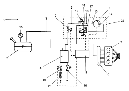
Fig. 2 schematically illustrates a second embodiment of the invention which
further
permits an onboard diagnosis of the arrangement. An additional valve 12 for
reversal of the flow direction is used. The air pump is connected with its
intake 13
and outlet 14 to the flow reversing valve 12. After flow reversal, air is
taken up from
the atmosphere and, when the regeneration valve 9 is opened, conveyed through
the regeneration conduit 5 towards the adsorption filter 4 and fuel tank 2.
The air
intake valve 10 is then closed. In order to avoid an excessive pressure in the
fuel
tank 2 and in other parts of the arrangement and to allow a reliable leak
diagnosis,
the fuel tank 2 is provided with a pressure sensor 15. After a preselected
diagnosis
pressure is reached, the regeneration valve 9 is closed and an eventual
pressure
drop measured. An overpressure valve 18 is further provided between an intake
manifold 16 and a pressure manifold 17 of the air pump 8, which valve provides
a
bypass at excessive pressure and short circuits the pump 8. In order to be
able to
exactly determine the fill level of the tank and to allow a very exact leak
testing, a
throttle 20 with defined output opening can be switched into the circuit
between the
fuel tank 2 and the regeneration valve 9 by way of a shut-off valve 19. In the
embodiment shown, the shut-off valve 19 together with the throttle 20 is
connected
to the adsorption filter 4.
The diagnosis procedure is carried out, as described above, with initially
closed
shut-off valve 19 and is subsequently repeated after a new pressure buildup
with the
shut-off valve 19 opened. The fill level of the tank can be calculated from
the time
difference between the testing with closed and opened throttle 20. The control
of the
air pump 8, the switching valve 12, the regeneration valve 9, as well as the
shut-off
valves 10 and 19 is carried out by way of the engine management system 11. The
broken lines indicate the respective connecting cables.
In a practical embodiment, the air pump 8, the switching valve 12, the over
pressure
valve 18 and the regeneration valve 9 are combined into a single unit 22. This
unit or
CA 02272526 1999-OS-21
....... _6_
module can also be readily replaceably mounted in the fuel tank venting
arrangement directly on the engine 7. Its parts are shown within the rectangle
in
broken lines.
Changes and modifications in the specifically described embodiments can be
carried
out without departing from the scope of the invention which is intended to be
limited
only by the scope of the appended claims.