Note: Descriptions are shown in the official language in which they were submitted.
CA 02272827 2006-O1-17
BACKGROUND OF THE INVENTION
International Application WO 96/41760 describes an
apparatus for conveying products to a packing machine. The
apparatus has two parallel, separately driven endless
conveyor chains which carry, along less than one half of
their circumferential lengths, carrier elements arranged at
uniform distances from one another and extending from the
respective chains. The carrier elements advance the
products on a slotted slide plate from a receiving station
through a work section to a discharge station where the
products are packed in a tubular bag.
International Application WO 97/42108 describes a similar
apparatus in which the two parallel conveyor elements are
toothed belts.
U.S. Patent No. 4,577,453 describes a conveyor apparatus
which has but a single conveying element and wherein the
products are, at the transfer station, first pushed in
groups onto a table and are thereafter deposited by separate
-2 -
CA 02272827 1999-OS-26
pushers into a packing container perpendicularly to the
discharging direction.
SUMMARY OF THE INVENTION
3
It is an object of the invention to provide an improved
conveyor apparatus of the above-outlined type with which
packing containers may be charged with products in a
rational manner.
This object and others to become apparent as the
specification progresses, are accomplished by the invention,
according to which, briefly stated, the conveyor apparatus
includes first and second parallel-spaced endless conveyors
extending from a receiving station to a first transfer
station for moving products in an advancing direction from
the receiving station to the first transfer station and a
plurality of product-carrying elements mounted on the first
and second conveyors at a uniform spacing from one anather.
The product-carrying elements mounted on the first conveyor
form a first group of product-carrying elements and the
product-carrying elements mounted on the second conveyor
form a second group of product-carrying elements. The first
and second groups extend over one part of the length of the
respective first and second conveyors. A.drive moves the
first and second conveyors independently from one another
-3 -
CA 02272827 1999-OS-26
such that products are conveyable from the receiving station
to the first transfer station alternatingly by the first and
second conveyors. A discharge mechanism, situated at the
first transfer station, includes a plurality of product-
s pushing elements for displacing products transversely to the
advancing direction away from the product-carrying elements.
The product-pushing elements are spaced identically to the
spacing of the product-carrying elements. A third conveyor
extends from the first transfer station to a second transfer
station. Receiving elements are mounted on the third
conveyor for carrying containers from the first transfer
station, where products are placed into the containers by
the product-pushing elements, to the second transfer
station.
IS
BRIEF DESCRIPTION OF THE DRAWINGS
Figures 1 and 2 are schematic side elevational views of a
preferred embodiment of the invention.
Figure 3 is a schematic end elevational view of a
transverse product-discharging device forming part of the
preferred embodiment.
Figure 3a is a schematic end elevational view of a
transverse product-discharging device according to a variant
of the Figure 3 construction.
-4 -
CA 02272827 1999-OS-26
Figure 4 is a schematic end elevational view of a
container-positioning and discharging device~forming part of
the preferred embodiment.
Figure 5 is a schematic side elevational view of a
further preferred embodiment of the invention.
Figure 6 is a schematic sectional end elevation of yet
another preferred embodiment of the invention.
Figure 7 is a schematic side elevation of the structure
shown in Figure 6.
IO
DESCRIPTION OF THE PREFERRED EMBODIMENTS
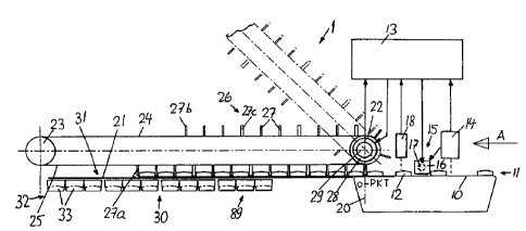
Turning to Figures 1 and 2, a supply belt 10 is arranged
upstream of a conveyor apparatus 1 as viewed in the
IS direction A in which wafer-like products 12 (such as
biscuits) are advanced in a column 11. The products 12 may
be spaced at random from one another. While the conveyor
belt 10 is driven to preferably run at constant speed, in
case it runs at variable speed, its drive motor is connected
20 with an angular position transmitter which, in turn, is
connected with a control device 13 of the apparatus 1.
Above the conveyor belt 10 a product sensor 14 is disposed
which measures the dimensions and shape of the product 12
passing thereunder and compares the sensed magnitudes with
25 inputted and/or learned desired values. Such a measuring
-5 -
CA 02272827 1999-OS-26
step determines not only the outer shape (footprint) of the
product 12 and its length on the conveyor belt 10, but also
the upper face thereof. In case the deviations from the
desired product configuration exceed predetermined
tolerances, a signal is directly applied to an ejection unit
which pushes the respective product 12 downstream of the
sensor 14 in a direction transverse to the conveying
direction A from the conveyor belt 10 into a non-illustrated
receptacle. The ejection unit 15 may include a pusher 16
10 which is briefly operated by an actuator 17 or may include a
nozzle which emits a short air blast to remove the defective
product 12. Downstream of the ejection unit 15 and
immediately upstream of a receiving station 20 of the
apparatus 1 a further sensor 18 is arranged which may be an
15 optical barrier operating with reflected light and which, by
means of the control unit 13, ensures. an accurate, cycled
introduction of the products 12 into the apparatus 1 at the
receiving station 20.
The apparatus 1 includes a sheet metal slide 21 and two
endless, parallel toothed belts 24, 25 supported on end
sprockets 22, 23 and positioned above the slide 21. A group
26 of uniformly spaced product-carrying elements 27 extends
from each belt 24, 25. The group length is shorter than
one-half of the circumferential length of each belt 24, 25.
The two sprockets 22 situated at the receiving station 20
-6 -
CA 02272827 1999-OS-26
are driven by separate motors 28 each having an angular
displacement sensor 29. The motors 28 are controlled by
the control apparatus 13 in such a manner that in each
instance one product-carrying element 27 arrives immediately
in front of a product 12 at the receiving station 20 and a
successive, second product-carrying element 27 of the same
group 26 arrives immediately behind the product 12, and such
second product-carrying element 27 advances the product 12
on the slide 21. The motors 28 are controlled in such a
manner that at the receiving station 20 in each instance the
leading product-carrying element 27a of one group 26 adjoins
the trailing product-carrying element 27b of the other group
26 immediately without an intermediate space as shown in
Figure 1. The control of the motors 28 may be effected, for
example, as described in the earlier-noted International
Application WO 96/41760. As soon as the trailing product-
carrying element 27b of one group 26 engages a product 12
(Figure 1), the corresponding belt 25 is accelerated (Figure
2) until the group 26 is aligned on the horizontal work
portion 31 with the groups 32 of packing containers 33 which
are disposed at a transfer station 30 laterally of the slide
21 and parallel thereto. When such an alignment is reached,
the belt 25 is stopped and the products 12 of the entire
group 26 are simultaneously laterally pushed into the
containers 33 by a mechanism to be described later. For
CA 02272827 1999-OS-26
maintenance work, the two toothed belts 24, 25 may be
individually or together pivoted about the axis of the
sprocket wheels 22 as illustrated in phantom lines in Figure
1. If a pivotal motion about the downstream end sprockets
23 is preferred, then expediently it is the end sprockets 23
which are driven by the motors 28.
Figure 3 schematically illustrates an exemplary mechanism
for pushing out the products 12 at the transfer station 30.
The slide 21 has, at the transfer station 30, a series of
transverse slots 38 spaced identically to the spacing of the
product-carrying elements 27: in any case, two slots 38 are
provided for every intermediate space between adjoining
product-carrying elements 27. An upwardly bent end 39 of a
pusher 40 projects through each of the slots 38. The
pushers 40 are affixed to a joint bar 41 which is swingably
supported at its opposite ends by two pivotal levers 42.
The two levers 42 are connected rigidly to one another by a
joint shaft 43 which extends parallel to the conveying
direction A. The levers 42 are pivotal about the axis of
the shaft 43. The bar 41 is rigidly connected with one end
of a lever 44 whose other end is jointed to a carriage 45.
The carriage 45 is horizontally shiftably guided on a
carriage support 46 which, in turn, is vertically
displaceably guided in a housing 47 of the conveyor
apparatus 1. A disk 51 is connected with a shaft 52 which
_g _
CA 02272827 1999-OS-26
extends parallel to the shaft 43. During the ejecting
motion, a motor 53 rotates the shaft 52 in each instance
through one revolution. On the disk 51, on one side
thereof, an eccentric pin 54 is mounted which is coupled
with the carriage 45 by means of a link rod 55. On the
opposite side of the disk 51 a cam disk 56 is mounted which,
by means of a follower roller 57, a pivotal two-arm lever 58
and a linkage rod 59, causes the vertical motion of the
carriage support 46. During the ejection motion, the
corresponding belt 25 is at a standstill and the carriage
support 46 is in its shown raised position, so that the
upwardly bent end 39 of the pushers 40 displaces the column
of the products 12 within the group 26 from the product-
carrying elements 27 transversely to the conveying direction
A into the containers 33 (not shown in Figure 3). The
elements 44, 45 and 46 as well as 55-59 are offset in the
axial direction of the shaft 53 in such a manner that the
containers 33 have sufficient space adjacent the slide 21.
For executing a return stroke, the carriage support 46 is
lowered by means of the cam disk 56 and the lever 58 so that
as early as the duration of such a return stroke, the
product-carrying elements 27 of one group 26 may be moved
away by means of the belt 25 from the region of the transfer
station 30. During the ejection of the products 12 at the
transfer station 30, the products 12 are, at the receiving
-9 -
CA 02272827 1999-OS-26
station 20, introduced between the product-carrying elements
27 of the second group 26 of the then advancing other belt
24. The ejecting operation is repeated thereafter for the
second group 26.
Instead of the above-described crank and cam disk drive
shown in Figure 3, it is feasible to operate the carriage
support 46 and the carriage 45 by linear motors 60, 61 as
shown in Figure 3a.
Figure 9 illustrates the transfer station 30 without the
elements 44-59 (which are axially offset). At the transfer
station 30 on that side of the slide 21 which is oriented
away from the pushers 40, a conveyor member 64 is arranged
which is formed of two parallel endless chains 65, each
supported by two end sprockets 66, 67. The two end
sprockets 66 and the two end sprockets 67 form respective
coaxial sprocket pairs. The sprocket pair composed of the
sprockets 66 is driven by a motor 68 having an angular
displacement sensor 69. The motor 68 and the sensor 69 are
connected to the control device 13. Carriers 70 are mounted
on the chains 65 and extend uniformly spaced therebetween.
Receiving elements 71 for accommodating the packaging
containers (trays) 33 are selectively secured to the
carriers 70 such that the open end 73 of the containers 33
is oriented at the transfer station 30 approximately
horizontally or vertically. In Figure 4, for purposes of
-10 -
CA 02272827 1999-OS-26
illustration, the receiving elements 71 are shown
alternatingly in these two positions. In reality, all
receiving elements 71 of the conveyor member 64 are mounted
only in the one or in the other orientation. In a first
case the groups 74 of products 12 are formed in the
containers 33 in such a manner that the edge of each product
12 of the formed groups 74 touches the bottom 75 of the
container 33. In a second case, the flat large surface of
one product lies on the container bottom 75. In the first
case, after each ejecting process, the chains 65 are
incrementally moved forward one step corresponding to the
thickness of the products 12 until the respective containers
33 are filled. Thereafter, a feeding step follows,
corresponding to the division of the carrier 70 less the
thickness of the groups 74. In the second case, the chains
65 are advanced in such a manner that the opening 73 at the
transfer station 30 in each instance arrives just underneath
the upper side of the slide 21. As soon as the respective
container 33 is filled, a feeding step takes place which
corresponds to the length of the division (spacing) of the
carriers 70.
At the lower sprockets 67 the containers 33 are caught at
a transfer station 77 by a group of fingers 78 which project
through non-illustrated slots provided in the receiving
elements 71. The filled containers 33 slide on the sloping
-11 -
CA 02272827 1999-OS-26
upper face 79 of the fingers 78 onto a removal conveyor belt
80. At the upper sprockets 66 the empty containers 33 are
introduced into the receiving elements 71 by means of known,
non-illustrated means.
Figure 5 illustrates a further embodiment according to
which the product-carrying elements 27 are T-shaped as
viewed laterally that is, at their free ends horizontal
product-supporting elements 84 extend which fully carry the
products 12 from the receiving station 20 to the transfer
l0 station 30 and therefore the slide 21 is dispensed with.
Figures 6 and 7 show a further variant in which the toothed
belts 24, 25 or the conveyor chains are situated underneath
the working section 31. The product-carrying elements 27
are mounted on carrier bodies 85: one group 26 of carrier
IS bodies 85 is secured to the belt 24, while the other group
26 of carrier bodies 85 is secured to the belt 25. The
carrier bodies 85 have product supporting surfaces 86 on
either side of the product-carrying elements 27 (with the
exception of the two ends of the groups 26).
20 A great extent of flexibility may be achieved with the
apparatus according to the invention. The products 12 may
be placed into the containers 33 selectively in an edgewise
or in a flatly stacked orientation. A modular construction
of the apparatus 1 is feasible. The filling of groups 74
25 into the containers 33 requires only a few steps resulting
-12 -
CA 02272827 1999-OS-26
in a gentle handling of the products 12. A large output
rate of up to 800 pieces per minute may be achieved. A
series of packing containers 33 may be simultaneously
charged with products. In Figures 1, 2 and 5 the containers
to be charged with the products are shown as four side-by-
side arranged container groups 89, wherein each group 89 is
composed of three interconnected containers 33. The distance
between adjoining containers belonging to different groups
89 is somewhat greater than the container distance within
one and the same group 89. Accordingly, the pusher groups
26 too, are subdivided by the product-carrying elements 27
into three subgroups which are separated from one another by
correspondingly thicker product-carrying elements 2?c.
These periodically non-uniform intervals between the
IS product-carrying elements 27 are programmed in the control
device 13, so that with signals from the sensor 18, an
angular sensor relating to the drive of the belt 10 and an
angular sensor 29, a cycling of the products 12 between the
product-carrying elements 27 is effected in an accurate
manner. Thus, in case of a supply rate of the products 12
on the belt 10 of approximately ?20 pieces per minute, the
clock frequency of the ejection step is 1 Hz. In case of
longer group 32 of containers 33 and a longer work section
31 the clock frequency may be further reduced.
-13 -
CA 02272827 1999-OS-26
It will be understood that the above description of the
present invention is susceptible to various modifications,
changes and adaptations, and the same are intended to be
comprehended within the meaning and range of equivalents of
the appended claims.
-14 -